Aristo Craft Train Engineer Revolution
PWC-->Linear Converter ART57091
revised 09-30-11
I recently wrote up some notes on using the Aristo Craft Base Station to power other Revolution receivers. This article gives details on how PWC / PWM is used to control a train's speed. It can be found here: link to article.
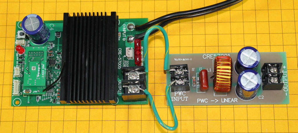
The experiments performed in the article mentioned above showed that the Revolution equipment worked best when a bridge rectifier was placed between the power from the base station and the Revolution receivers. Aristo Craft just completed design and production of a solution that completely removes the PWC / PWM waveform from the base station so that it supplies truly linear power. This should solve any problems associated with equipment that does not work well or at all with PWC / PWM power.
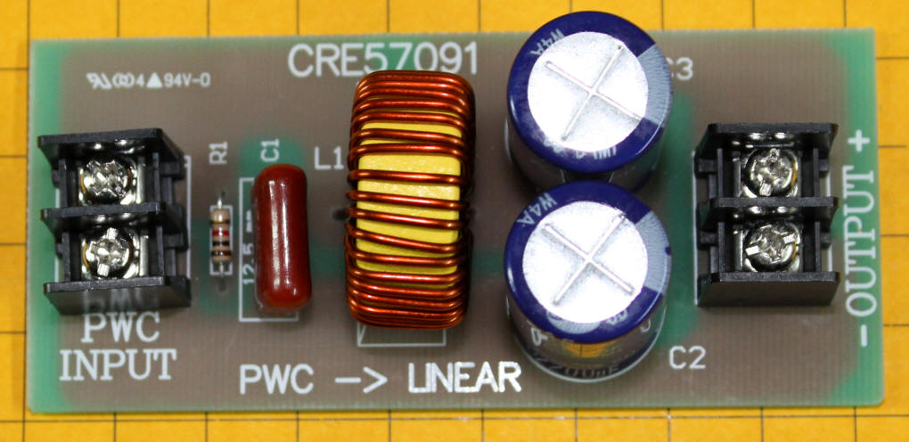
The unit is about 1 3/4" x 3 1/2" x 1 1/8" high. It has two screw terminals on one end that connect to the output from the Revolution Base Station (labeled PWC INPUT) and two screw terminals on the other side that supply linear power. These terminals are labeled "- OUTPUT +" but this is misleading. The polarity of the output is not fixed as the label implies, but follows the polarity of the input voltage. If the Revolution transmitter is set to forward, voltage of one polarity is delivered at the output. If the direction of travel is changed the polarity changes as well.
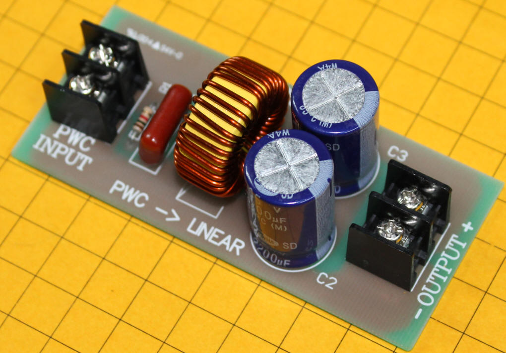
The blue devices with silver tops are capacitors. The large device next to them is a toroidal choke, an inductor, which does most of the work converting PWC to Linear.
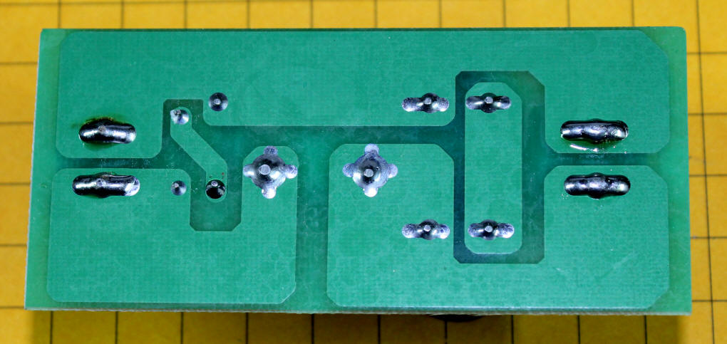
This view of the back of the board shows how simple the circuit is.
At first glance you might be concerned about there being two polarized capacitors on the board without a bridge rectifier to protect them from incorrect polarity on the input side of the board. Since the capacitors are wired back to back with their negative leads tied together they perform as though they are a non-polarized capacitor. This is a nice solution as it removes the need for a bridge rectifier that would have dropped the output voltage from the Base Station and had the potential to generate considerable heat when used with larger engines.
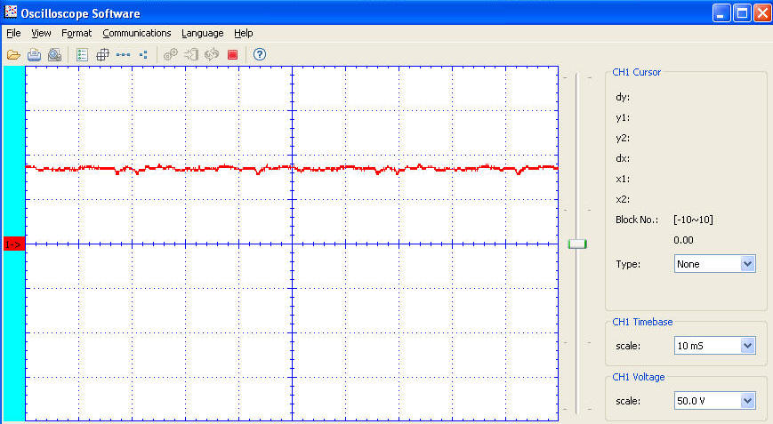
The oscilloscope trace shown below is of the output of the PWC --> Linear converter when the throttle on the Base Station is set to 50% power. You can see that the output is nearly a straight line. What variations there are shown are likely due to noise that is generated by the motor that is being used as a load.
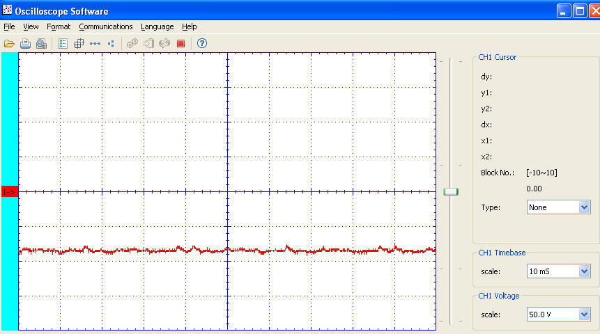
Here is the same 50% throttle setting but with the direction reversed. The voltage is below the center line indicating a negative polarity.
I tested the converter and the Base Station while powering other Revolution equipped locomotives and, as expected, they worked perfectly. The new converter is a simple circuit that does just what is advertised. It removes all vestiges of the PWC / PWM from the output of the Revolution Base Station. For those model railroaders who want to use the Base Station to feed track that powers other Revolution receivers is it an ideal solution!