Aristo Craft's original Revolution receiver did not have a built-in sound unit. If a model railroader wanted to add sound the receiver had to be interfaced to a 3rd party sound card from Dallee, Phoenix or some other company.
The latest Revolution receiver comes with sound. It can be ordered with diesel sound (part # CRE57002SD ) or steam sound (part # CRE57002SS ). These sounds are called "generic" steam and diesel and Aristo Craft intends to make more sounds available in the future as the receivers are designed to accept new sound files.
This article is intended to give a detailed review of the new Revolution receiver. In addition to a technical overview of how it is constructed it includes a number of details about the board's operation that may not be readily apparent to the user.
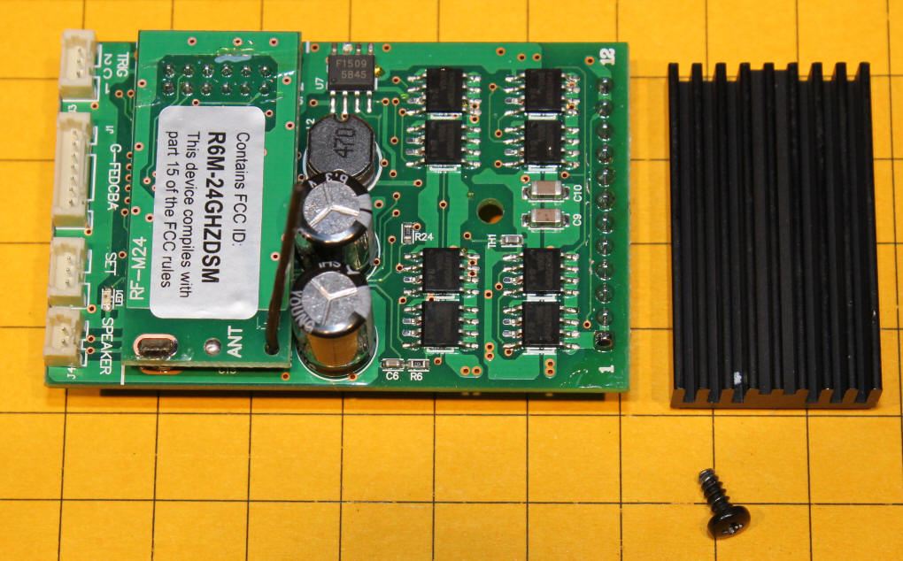
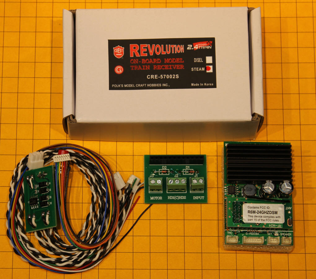
These items are included in the box.
Here are the accessories that come with the sound receiver. In addition to the items that came with the original board there is a connection for the speaker and for the trigger that is used for the chuff on the steam locomotive. The non-Plug & Play board has a nice set of screw terminals that connect to the locomotive's motor, front and rear lights and track or battery power connections.
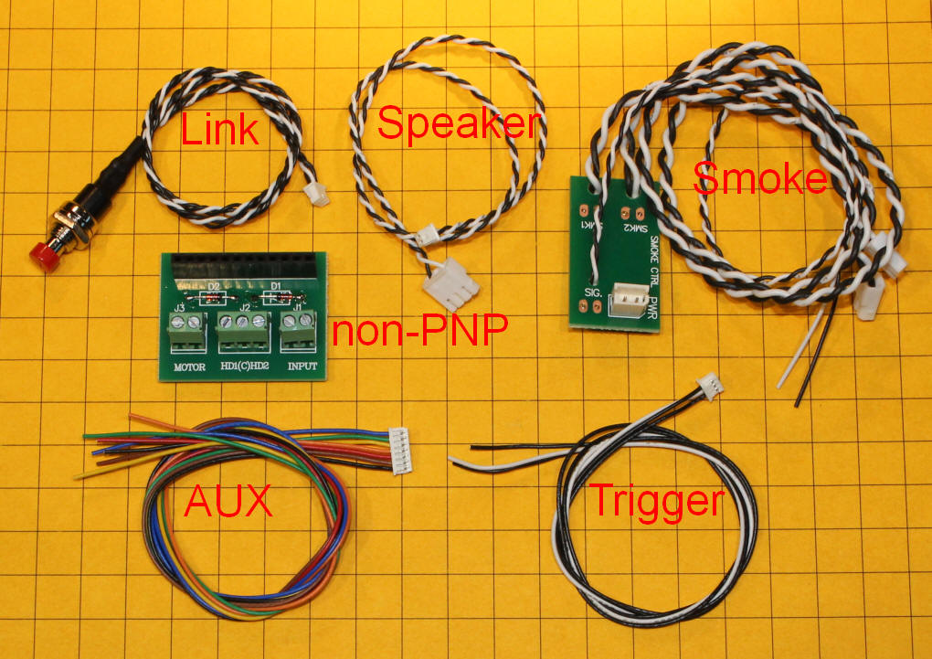
When the time comes to plug in the auxiliary harness, trigger, speaker cable and link button wires take care that you insert them with the correct orientation. There is a row of pins within each socket on the receiver. By examining how these pins are offset you can tell how the plug must be inserted. If you need to remove a cable don't just pull on the wire but use a small blade or screwdriver to pry the plug from its socket. This is especially true of the speaker cable as it has only two pins and the socket can easily be pulled from the board if the cable is yanked.
The Receiver
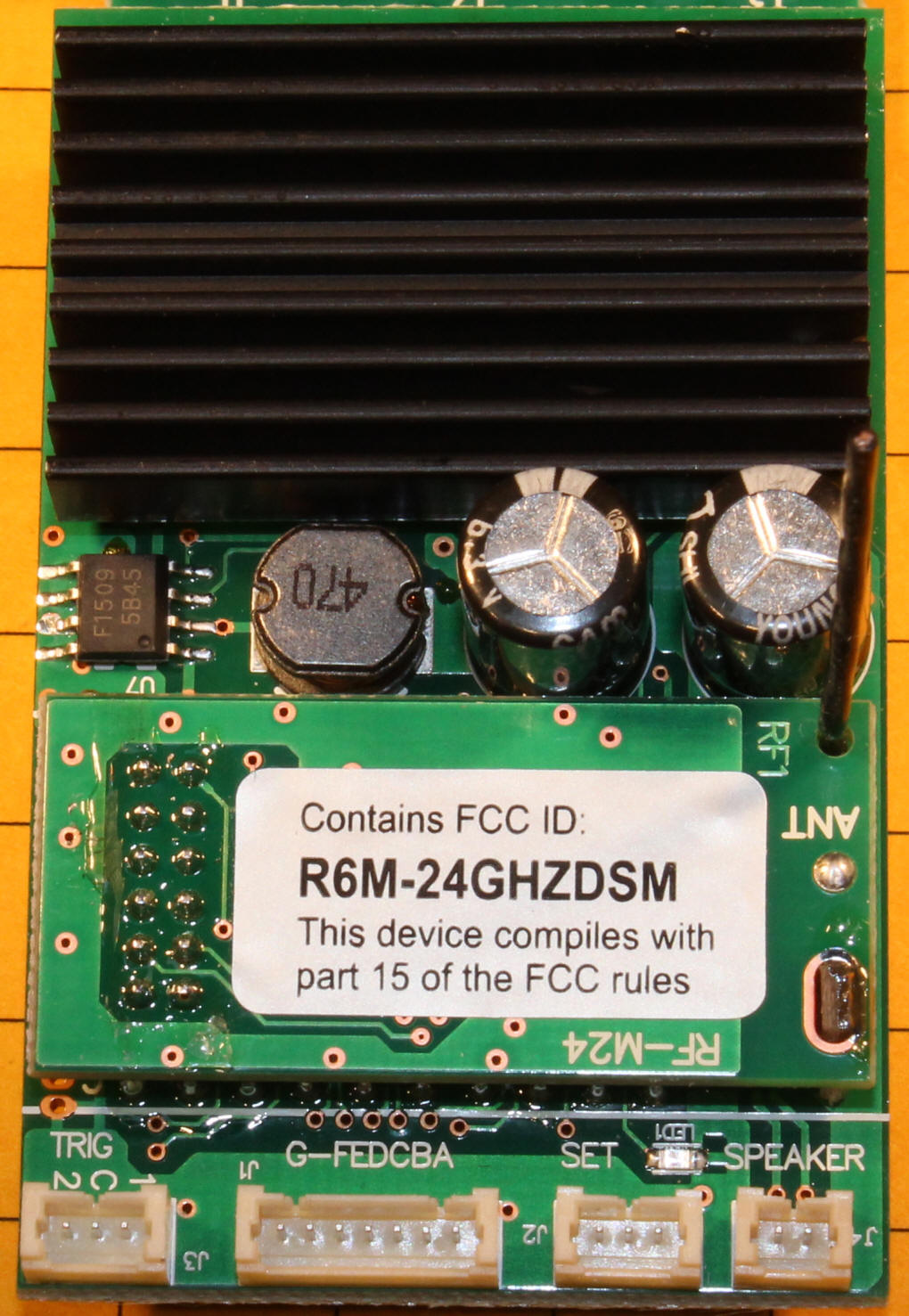
The items that you see in this photo are, top to bottom, a black
heat sink, a choke and two large capacitors, a daughter board that
contains the radio and a group of connections. The small black
wire that is sticking up on the right is the antenna.
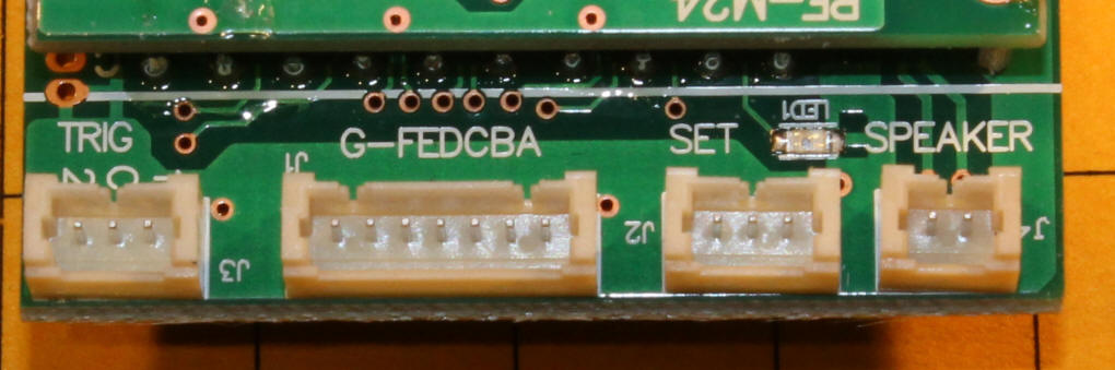
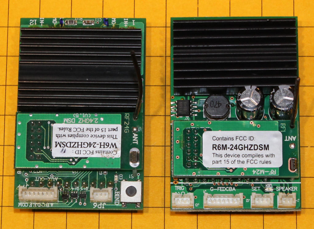
This close-up of the connections shows, left to right, the trigger (used for chuff and whistle on the steam card and bell and whistle on the diesel), the auxiliary interface, the bind or link button and the speaker. Note the small LED just to the left of the letter "S" in Speaker. This LED blinks when the receiver is waiting to bind.
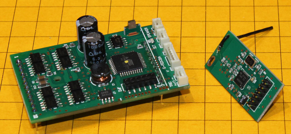
The original board (on the left) and the sound board (right) are the same size in length and width. The new board is a bit higher, 22.5mm from the bottom of the pins to the top of the capacitors vs 17mm to the top of the heat sink.
Testing
the Sound Receiver
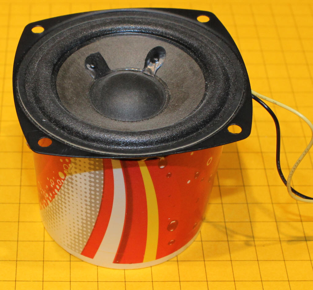
My test setup is
shown here. The small speaker at the top has an impedance of 8
ohms. I did not have the
correct female connector to attach the speaker to the Revolution's speaker cable so I
just used some short wire leads for a temporary connection.
The link switch is at the right. Remember that you have to hold that switch for a few seconds to initiate linking.
The red and green LEDs to the left are used to test the forward and rear light outputs. The center connection is positive and the other two connections are negative. I connected a 470 ohm resistor to both of the LED's anodes and joined them together where they attach to the center terminal.
Power goes into the lower terminals and the locomotive's motor connects to the top terminals.
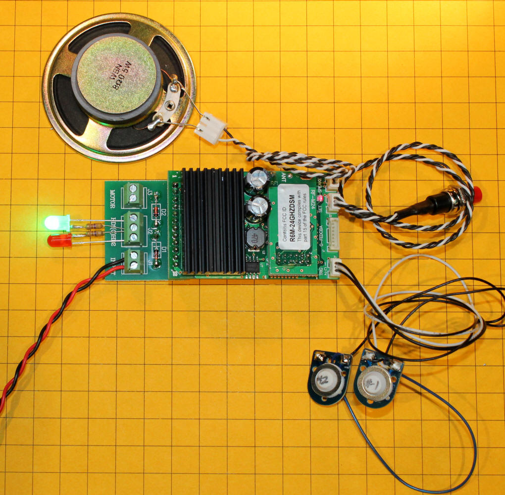
The two small switches in the lower right connect to the trigger leads. The center lead is the white wire and is the common connection. One of the black wires goes to a terminal labeled 1 while the other goes to 2. If you momentarily connect terminal #1 to the common lead the whistle will sound. This would be useful if you wanted to trigger the whistle each time the locomotive passed a particular point on the railroad. A reed switch and magnet could be used to make this happen.
On the steam sound board the other connection, #2, activates the locomotive's chuff sound. If you don't connect to #2 the chuff is automatically tied to the motor speed. If the chuff connection is used the automatic chuff halts and the physical chuff switch takes over. If you want to go from switch activated chuff back to automatic chuff, power must be removed from the receiver to reset the mode. On the diesel sound board connection #2 sounds the bell.
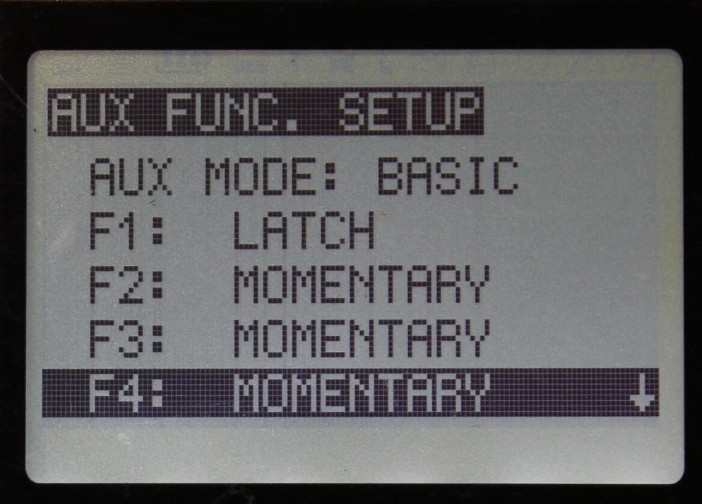
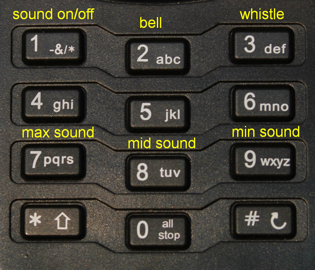
The buttons on the Revolution transmitter are used with the sound as shown in this table. Make sure that you set the first button to latching rather than the default momentary setting. This is done in the transmitter when you configure the a new receiver. It is under ASSIGN FUNCTIONS / n. AUX FUNC SETUP / F1 - change from the default MOMENTARY to LATCH by pressing the left arrow key.
The sound controls use buttons 1, 2, 3, 7, 8 and 9 on the transmitter's keypad. This leaves buttons 4, 5 and 6 available to activate other accessories like the smoke unit.
| Button | |
| 1 | Turn sound on or off - must be set to latch |
| 2 | Bell - set to momentary |
| 3 | Horn - set to momentary |
| 4 | Available for smoke, etc |
| 5 | Available for smoke, etc |
| 6 | Available for smoke, etc |
| 7 | High Volume |
| 8 | Medium Volume |
| 9 | Low Volume |
| 0 | No function |
I tested the status of the auxiliary outputs on the sound receiver to see if they still functioned when the sound was activated. As I suspected they were still operable. This means that when you turn the sound on with button 1 on the transmitter, auxiliary connection #1 is active and when you press button 3 to sound the horn auxiliary connection #3 is briefly active. This could come in handy as it would allow you to activate ditch lights in the locomotive when the horn or bell is sounded.
The speakers that are installed in most Aristo Craft locomotives have an impedance of 8 ohms. If you use the sound receiver with your own speaker or speakers you should try to use speakers with a similar rating. If you want to use two speakers in a larger locomotive you could use two 4 ohm speakers, wiring them in series.
If you do choose to use your own speaker remember that the quality of the sound can be greatly enhanced by placing the speaker in a baffle made from a section of a paper cup or similar enclosure.
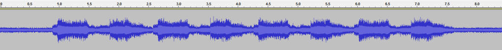
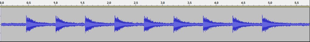
When button #2 is pressed on the steam sound board the bell rings for about 7 seconds. When button #3 is pressed the whistle sounds for about 18 seconds. The whistle does not signal a grade crossing (two longs, a short and a long) but group of three long blasts.
I found the sound to be quite acceptable. It is not on the level of high end sound boards but it is very good considering the price and the utility of having it built into the receiver.
The bell, whistle and chuff all can be on at the same time. Some inexpensive sound cards shut down one sound when another is called for.
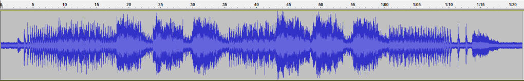
Here are some sample sounds from the units. I used two high quality 4 ohm speakers wired in series with baffles on each for the recordings. I did not maintain the same spacing between the speakers and microphone so the variations in loudness shown in the graphs are due variations in my setup.
Steam bell only - one button press. Click on the image below to hear the MP3 file or right click, save and play.
Steam whistle only - one button press. Click on the image below to hear the MP3 file or right click, save and play.
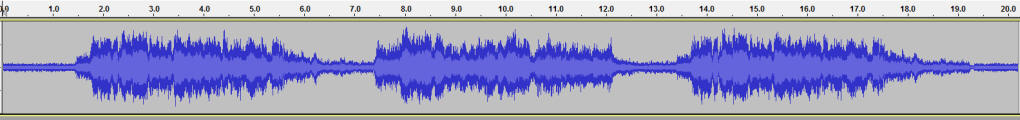
Steam chuff, whistle & bell - click on the image below to hear the MP3 file or right click, save and play.
Diesel bell only - one button press. Click on the image below to hear the MP3 file or right click, save and play
Diesel whistle only - one button press. Click on the image below to hear the MP3 file or right click, save and play.

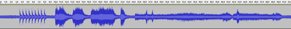
Diesel prime mover, bell, whistle, speed up, reverse then stop - click on the image below to hear the MP3 file or right click, save and play.
The sound unit is capable of producing sound at a respectable volume. The units I tested, however, showed a significant difference in the volume level between the diesel and steam sound files. The two recordings below are of the whistle on the two units. First the whistle is sounded at the lowest sound level (#9 on the transmitter's keypad) then at medium (#8) then at high volume (#7). I am confident that this variation in sound level is something that can be corrected in a future release of the software.
The recordings made in this section were done with the same speaker / microphone spacing so that relative loudness levels can be seen and heard.
Diesel -Click on the image below to hear the MP3 file or right click, save and play.

Steam - Click on the image below to hear the MP3 file or right click, save and play.

If you find that the lowest volume setting still produces too loud a sound you can try wiring a small value (10ohn --> 30 ohm) resistor in series with the speaker. Perhaps in future releases the sound board will allow the volume to be incrementally increased and decreased with only two buttons, rather than having three buttons select one of the fixed volume levels.
- Cost for a remote control receiver & sound is very reasonable
- Compact size
- Plug-n-Play on many locomotives
- Simple operation with the existing transmitter (no upgrade needed)
- More than ample volume for outside use
- Smoke board included
- Two trigger inputs that can be used for chuff and other sounds
- Software upgradeable
...& Cons...
- Whistle sound is fixed at three long blasts
- Sound quality could be better
- Lowest volume setting may still be too loud
- Diesel volume settings are quite a bit higher than those of the steam unit
- Only "generic" steam and diesel sounds available at this time
- Minimal documentation
... & Suggestions
- Change to a volume scheme where button 7 increases the volume in small increments, button 8 goes immediately to the middle volume and button 9 decreases the volume in small increments
- Allow end users to add additional sounds and modify existing sounds with a computer interface & software
- Make the small plugs for speaker, linking, triggers and auxiliary outputs available for purchase
- Change the whistle on both the diesel and steam units to a crossing signal (two longs, short, long)
- Change the bell sound so that it latches or only rings as long as the button is pressed. That is, press the button on the transmitter once to have it start and again to stop it if the button is set to latch. If it is set to momentary the bell would only ring when the button is held down.
I was impressed with the new and upgraded Revolution receiver with sound. The unit gives garden railroaders a simple way to add sound to their locomotives. Since much of the operation of the entire Revolution system is based on software I am confident that upgrades to both the sound unit and the other parts of the system will make it better and better as time goes by.
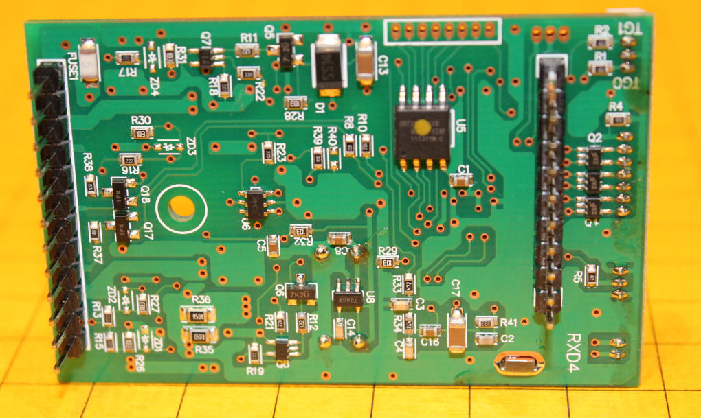
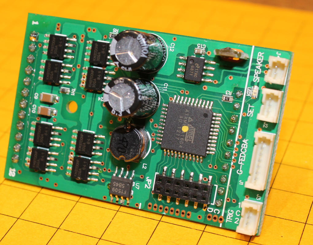
In this photo the heat sink has been temporarily removed to show the power devices that are under it. There are eight MOSFETs, part number kmb7d0np. These are 7 Amp, 30 V devices that contain both an N-Channel and a P-Channel MOSFET. These new chips are different from those used in the original receiver where there were separate devices for N-Channel and P-Channel. These are new devices that simplify design and manufacture and only present a 0.0235 ohm resistance to the circuit making the power unit quite efficient so that it generates very little heat.