160 LEDs Chasing Round & Round
d. bodnar 01-07-2017
| I have been experimenting with LED strip
lights for several years. The ones I have worked with were
usually of one color, usually white, red or blue. Recently a
newer type of LED has become available. These new strip lights
contain a number of RGB LEDs, each of which can display thousands
of different colors. Even more compelling is the fact that a
microcontroller cannot only control the LEDs color but it can
individually address each LED so that adjoining LEDs can be lit in
different colors at different brightness levels. I have a place on the G-scale train layout that I maintain at Pittsburgh's Children's Hospital where I put strange and/or whimsical things to entertain the children. I have put a number of different Rube Goldberg ball gizmos there and thought this might be a nice item to display there, too. |
| What is a NeoPixel? Google gives us this definition: “NeoPixel” is Adafruit's brand for individually-addressable RGB color pixels and strips based on the WS2812, WS2811 and SK6812 LED/drivers, using a single-wire control protocol. The thing that separates them from normal LEDs is that each LED in the array (be it a strip or circular or rectangular matrix) has a built-in controller that can be spoken to by an Arduino or other controller. These devices are called NeoPixels - more information can be found here: https://learn.adafruit.com/adafruit-neopixel-uberguide/arduino-library and at many sites on the Internet. The LEDs I have worked with are size 5050. This means that each LED is 5 mm square. Since these are RGB LEDs there are three emitters inside of each one, Red, Green and Blue - by varying the brightness of these colors thousands of different hues can be made. The LEDs are also very close together on the strip and in the circle at the top. Be sure you find such spacing on any that you order as some have the LEDs much farther apart. Such spacing is not ideal for this setup. |
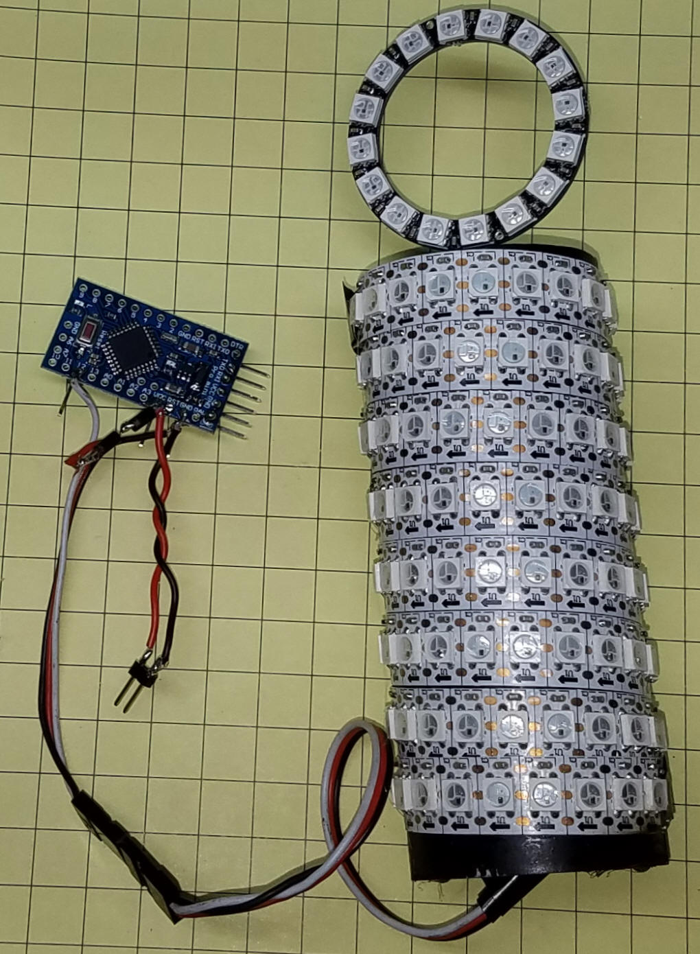
| Parts I used a 1 meter long strip of 144 LEDs for the spiral wrap around a section of PVC plastic pipe and a 16 LED circle array for the top.
|
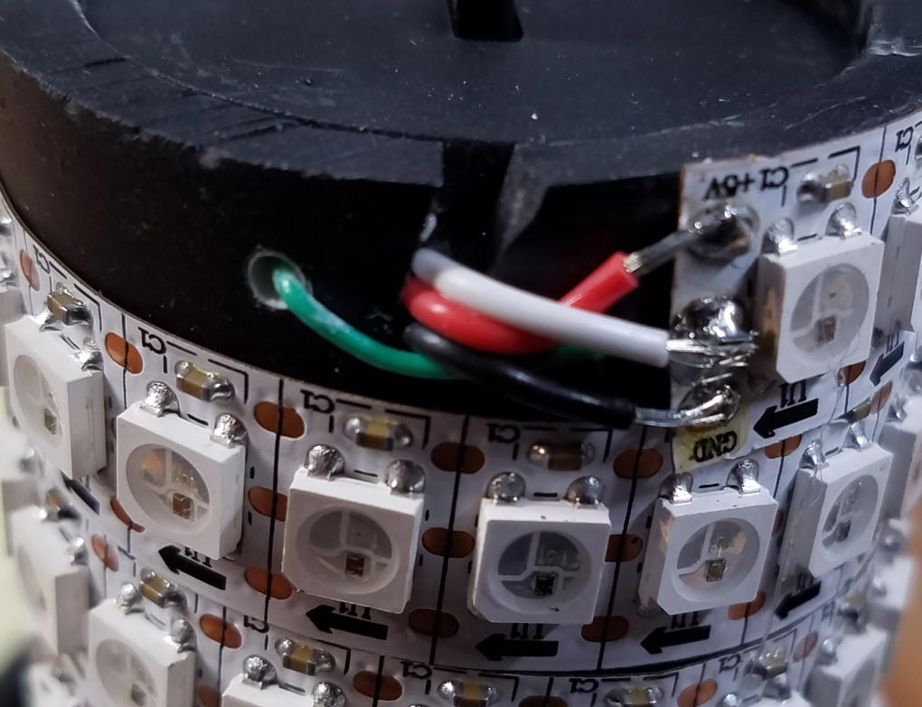
| Wiring Each LED strip has three connections at each end. One is for +5 volts, one for ground and one for data. At one end the data pin is marked as IN and at the other end it is marked OUT. Some strips indicate this with an arrow showing the direction from IN to OUT and some just use I or O. The IN pins are connected to the Arduino. The OUT pins can be connected to the IN pins on another strip of lights or, as in this case, to a round LED array.
I found that running the system on as few as 3.5 volts still gave a very intense light that was a bit too much for use on the layout at Children's Hospital. Lowering the input voltage to get dim enough LEDs sometimes crashed the Arduino so I opted to run the Arduino at 5 volts and used two 1N4001 diodes (just about any silicon diode would work) to drop the voltage going to the LEDs by 1.4 volts. To give me even more control I used a variable output buck converter to alter the input power until the LEDs were "just right"! Make sure that the bands on the diodes point to the LEDs. Each diode drops the voltage by about 0.7 volts. You can use 1, 2 or 3 diodes should you want to dim things on your device.
|
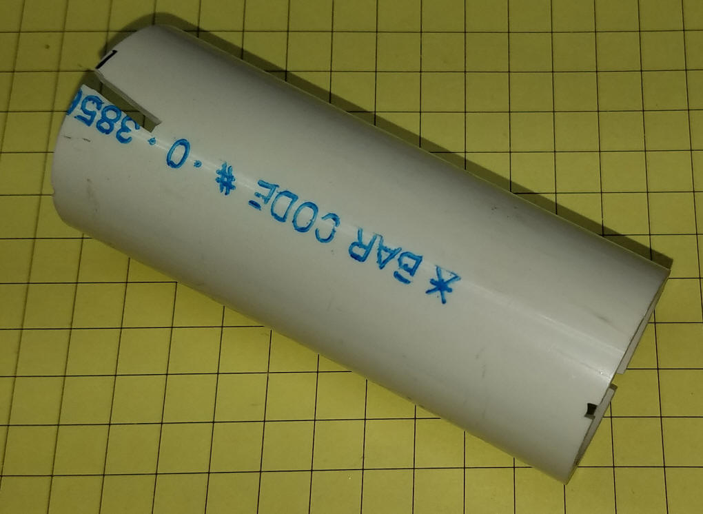
| Building Cut a notch at one end to pass the wires from the LED strip to the inside of the 4" long PVC tubing. I found that a similar notch at the other end of the tube needed to be 1/2 way around the tube to pass the wires at the other end of the strip - your strip may be slightly longer or shorter and need a different placement. I also angled the notches a small amount to accommodate the diagonal wrap of the LED strip around the tube. I painted the tube section with flat black spray paint before wrapping.
Here the wires at the bottom of the tube pass through the notch.
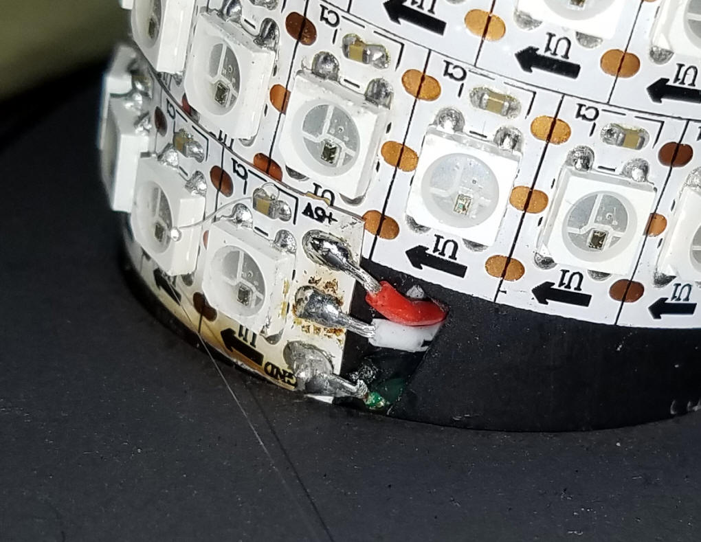
At the top the other end of the strip has it wires go through the notch where they will connect to the 16 LED ring. The green wire passing through the small hole was soldered to one of the contacts on the LED strip and was used to pull the strip taut when wrapping the strip around the tube. Look carefully at the strip and you will see that this one uses an arrow to show "in" and "out" on the data pins.
The completed unit with the 144 LEDs wrapped around the pipe and the 16 LED ring at the top. There are two diodes on the power line to the LEDs that can be seen by the VCC pin on the Arduino. Power is applied to the red/black wires.
|
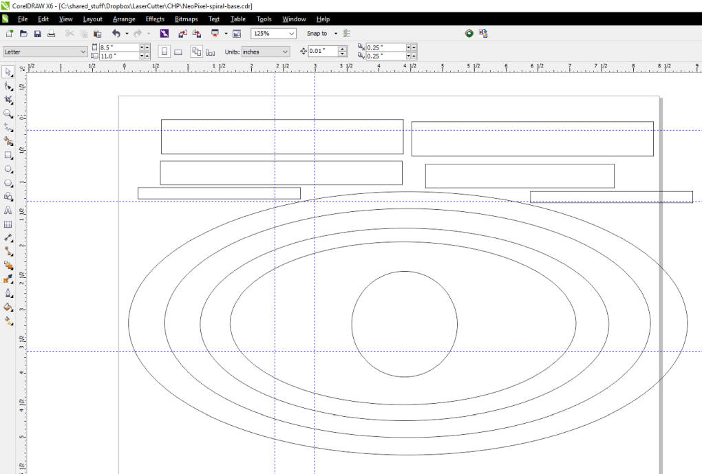
| A Base To support the pipe you need a base with an appropriately sized hold and room to accommodate any electronics (Arduino and/or buck converter) that you want to use. If found that the Arduino Pro Mini easily fit into the tube. The base that is shown here was cut from 1/4" MDF using my laser cutter. It was designed in CorelDraw and is made up of 4 telescoping sections. The rectangular blocks at the top are used to hold the sections at the right distance as they are glued together.
|
| Arduino Code This code is a combination of sketches from Adafruit and josh.com. I do not pretend to understand all of the tricks that are used by both of the examples but I love what they do!
Original Adafruit code & library is here:
https://github.com/adafruit/Adafruit_NeoPixel file name: strandtest-NANO160-v4-RWB-UpDown-combined-V2-1 // This sketch is a combination of code from Adafruit & from josh.com
// The Adafruit part needs their library while Josh does not use it.
// The code is not optimized and is not intended to be an example for others, it is
// just code that works!
#include <Adafruit_NeoPixel.h>
// Parameter 1 = number of pixels in strip
// Parameter 2 = pin number (most are valid)
// Parameter 3 = pixel type flags, add together as needed:
// NEO_RGB Pixels are wired for RGB bitstream
// NEO_GRB Pixels are wired for GRB bitstream
// NEO_KHZ400 400 KHz bitstream (e.g. FLORA pixels)
// NEO_KHZ800 800 KHz bitstream (e.g. High Density LED strip)
Adafruit_NeoPixel strip = Adafruit_NeoPixel(170, 12, NEO_GRB + NEO_KHZ800); // actually 160 /w ring - using 165 to get a pause at top
/// From Josh
/*
This is an example of how simple driving a Neopixel can be
This code is optimized for understandability and changability rather than raw speed
More info at http://wp.josh.com/2014/05/11/ws2812-neopixels-made-easy/
*/
// Change this to be at least as long as your pixel string (too long will work fine, just be a little slower)
#define PIXELS 160 //96*11 // Number of pixels in the string
// These values depend on which pin your string is connected to and what board you are using
// More info on how to find these at http://www.arduino.cc/en/Reference/PortManipulation
// These values are for the pin that connects to the Data Input pin on the LED strip. They correspond to...
// Arduino Yun: Digital Pin 8
// DueMilinove/UNO: Digital Pin 12
// Arduino MeagL PWM Pin 4
// You'll need to look up the port/bit combination for other boards.
// Note that you could also include the DigitalWriteFast header file to not need to this lookup.
//NOTE portb -4 is digital pin 12
#define PIXEL_PORT PORTB // Port of the pin the pixels are connected to
#define PIXEL_DDR DDRB // Port of the pin the pixels are connected to
#define PIXEL_BIT 4 // Bit of the pin the pixels are connected to
// These are the timing constraints taken mostly from the WS2812 datasheets
// These are chosen to be conservative and avoid problems rather than for maximum throughput
#define T1H 900 // Width of a 1 bit in ns
#define T1L 600 // Width of a 1 bit in ns
#define T0H 400 // Width of a 0 bit in ns
#define T0L 900 // Width of a 0 bit in ns
#define RES 6000 // Width of the low gap between bits to cause a frame to latch
// Here are some convience defines for using nanoseconds specs to generate actual CPU delays
#define NS_PER_SEC (1000000000L) // Note that this has to be SIGNED since we want to be able to check for negative values of derivatives
#define CYCLES_PER_SEC (F_CPU)
#define NS_PER_CYCLE ( NS_PER_SEC / CYCLES_PER_SEC )
#define NS_TO_CYCLES(n) ( (n) / NS_PER_CYCLE )
void setup() {
Serial.begin(9600);
strip.begin();
strip.show(); // Initialize all pixels to 'off'
ledsetup();
}
void loop() {
// The first few calls are to Josh's code
colorWipe2(255, 0, 0, 0); // Red
colorWipe2(0, 255, 0, 0); // Green
colorWipe2(0, 0, 255, 0); // Blue
// Send a theater pixel chase in...
theaterChase(127, 127, 127, 0); // White
theaterChase(127, 0, 0, 0); // Red
theaterChase( 0, 0, 127, 0); // Blue
rainbowCycle2(1000 , 20 , 5 );
detonate( 255 , 255 , 255 , 1000);
// These are using the Adafruit code
colorWipe(strip.Color(45, 0, 0), 1); // Red
colorWipeDown(strip.Color(0, 0, 0), 1); // blank
colorWipe(strip.Color(45, 45, 45), 1); // white
colorWipeDown(strip.Color(0, 0, 0), 1); // blank
colorWipe(strip.Color(0, 0, 45), 1); // Blue
colorWipeDown(strip.Color(0, 0, 0), 1); // blank
Serial.println("red");
oneLEDonlyUp(strip.Color(45, 0, 0), 1); // single red up
Serial.println("red2");
oneLEDonlyDown(strip.Color(45, 0, 0), 1); // single red down
Serial.println("green");
oneLEDonlyUp(strip.Color(0, 45, 0), 1); // single green up
Serial.println("green2");
oneLEDonlyDown(strip.Color(0, 45, 0), 1); // single green down
Serial.println("blue");
oneLEDonlyUp(strip.Color(0, 0, 45), 1); // single blue up
Serial.println("blue2");
oneLEDonlyDown(strip.Color(0, 0, 45), 1); // single blue down
rainbowCycle(2);
}
// Fill the dots one after the other with a color
void colorWipe(uint32_t c, uint8_t wait) {
for (int i = 0; i < strip.numPixels(); i++) {
strip.setPixelColor(i, c);
strip.show();
delay(wait);
}
}
void oneLEDonlyUp(uint32_t c, uint8_t wait) {
for (int i = 0; i < strip.numPixels(); i++) {
strip.setPixelColor(i, c);
strip.show();
strip.setPixelColor(i - 1, 0);
delay(wait);
}
}
void oneLEDonlyDown(uint32_t c, uint8_t wait) {
for (int i = strip.numPixels() - 1; i >= 0; i--) {
strip.setPixelColor(i, c);
strip.show();
strip.setPixelColor(i + 1, 0);
delay(wait);
}
}
void colorWipeDown(uint32_t c, uint8_t wait) {
for (int i = strip.numPixels(); i >= 1; i--) {
strip.setPixelColor(i, c);
strip.show();
delay(wait);
}
}
// Slightly different, this makes the rainbow equally distributed throughout
void rainbowCycle(uint8_t wait) {
int i, j;
for (j = 0; j < 256 * 4; j++) { // 4 cycles of all colors on wheel
for (i = 0; i < strip.numPixels(); i++) {
strip.setPixelColor(i, Wheel(((i * 256 / strip.numPixels()) + j) & 255));
}
strip.show();
delay(wait);
}
}
// Input a value 0 to 255 to get a color value.
// The colours are a transition r - g - b - back to r.
/// NOTE: all "55"'s were "255"'s
uint32_t Wheel(byte WheelPos) {
if (WheelPos < 85) {
return strip.Color(WheelPos * 3, 55 - WheelPos * 3, 0);
} else if (WheelPos < 170) {
WheelPos -= 85;
return strip.Color(55 - WheelPos * 3, 0, WheelPos * 3);
} else {
WheelPos -= 170;
return strip.Color(0, WheelPos * 3, 55 - WheelPos * 3);
}
}
// Actually send a bit to the string. We must to drop to asm to enusre that the complier does
// not reorder things and make it so the delay happens in the wrong place.
inline void sendBit( bool bitVal ) {
if ( bitVal ) { // 0 bit
asm volatile (
"sbi %[port], %[bit] \n\t" // Set the output bit
".rept %[onCycles] \n\t" // Execute NOPs to delay exactly the specified number of cycles
"nop \n\t"
".endr \n\t"
"cbi %[port], %[bit] \n\t" // Clear the output bit
".rept %[offCycles] \n\t" // Execute NOPs to delay exactly the specified number of cycles
"nop \n\t"
".endr \n\t"
::
[port] "I" (_SFR_IO_ADDR(PIXEL_PORT)),
[bit] "I" (PIXEL_BIT),
[onCycles] "I" (NS_TO_CYCLES(T1H) - 2),
[offCycles] "I" (NS_TO_CYCLES(T1L) - 2) s
);
} else { // 1 bit
// **************************************************************************
// This line is really the only tight goldilocks timing in the whole program!
// **************************************************************************
asm volatile (
"sbi %[port], %[bit] \n\t" // Set the output bit
".rept %[onCycles] \n\t" // Now timing actually matters.
"nop \n\t" // Execute NOPs to delay exactly the specified number of cycles
".endr \n\t"
"cbi %[port], %[bit] \n\t" // Clear the output bit
".rept %[offCycles] \n\t" // Execute NOPs to delay exactly the specified number of cycles
"nop \n\t"
".endr \n\t"
::
[port] "I" (_SFR_IO_ADDR(PIXEL_PORT)),
[bit] "I" (PIXEL_BIT),
[onCycles] "I" (NS_TO_CYCLES(T0H) - 2),
[offCycles] "I" (NS_TO_CYCLES(T0L) - 2)
);
}
// Note that the inter-bit gap can be as long as you want as long as it doesn't exceed the 5us reset timeout (which is A long time)
// Here I have been generous and not tried to squeeze the gap tight but instead erred on the side of lots of extra time.
// This has thenice side effect of avoid glitches on very long strings becuase
}
inline void sendByte( unsigned char byte ) {
for ( unsigned char bit = 0 ; bit < 8 ; bit++ ) {
sendBit( bitRead( byte , 7 ) ); // Neopixel wants bit in highest-to-lowest order
// so send highest bit (bit #7 in an 8-bit byte since they start at 0)
byte <<= 1; // and then shift left so bit 6 moves into 7, 5 moves into 6, etc
}
}
/*
The following three functions are the public API:
ledSetup() - set up the pin that is connected to the string. Call once at the begining of the program.
sendPixel( r g , b ) - send a single pixel to the string. Call this once for each pixel in a frame.
show() - show the recently sent pixel on the LEDs . Call once per frame.
*/
// Set the specified pin up as digital out
void ledsetup() {
bitSet( PIXEL_DDR , PIXEL_BIT );
}
// Just wait long enough without sending any bots to cause the pixels to latch and display the last sent frame
void show() {
_delay_us( (RES / 1000UL) + 1); // Round up since the delay must be _at_least_ this long (too short might not work, too long not a problem)
}
/*
That is the whole API. What follows are some demo functions rewriten from the AdaFruit strandtest code...
https://github.com/adafruit/Adafruit_NeoPixel/blob/master/examples/strandtest/strandtest.ino
Note that we always turn off interrupts while we are sending pixels becuase an interupt
could happen just when we were in the middle of somehting time sensitive.
If we wanted to minimize the time interrupts were off, we could instead
could get away with only turning off interrupts just for the very brief moment
when we are actually sending a 0 bit (~1us), as long as we were sure that the total time
taken by any interrupts + the time in our pixel generation code never exceeded the reset time (5us).
*/
// Display a single color on the whole string
void showColor( unsigned char r , unsigned char g , unsigned char b ) {
cli();
for ( int p = 0; p < PIXELS; p++ ) {
sendPixel( r , g , b );
}
sei();
show();
}
// Fill the dots one after the other with a color
// rewrite to lift the compare out of the loop
void colorWipe2(unsigned char r , unsigned char g, unsigned char b, unsigned char wait ) {
for (unsigned int i = 0; i < PIXELS; i += (PIXELS / 60) ) {
cli();
unsigned int p = 0;
while (p++ <= i) {
sendPixel(r, g, b);
}
while (p++ <= PIXELS) {
sendPixel(0, 0, 0);
}
sei();
show();
delay(wait);
}
}
// Theatre-style crawling lights.
// Changes spacing to be dynmaic based on string size
#define THEATER_SPACING (PIXELS/20)
void theaterChase( unsigned char r , unsigned char g, unsigned char b, unsigned char wait ) {
for (int j = 0; j < 3 ; j++) {
for (int q = 0; q < THEATER_SPACING ; q++) {
unsigned int step = 0;
cli();
for (int i = 0; i < PIXELS ; i++) {
if (step == q) {
sendPixel( r , g , b );
} else {
sendPixel( 0 , 0 , 0 );
}
step++;
if (step == THEATER_SPACING) step = 0;
}
sei();
show();
delay(wait);
}
}
}
// I rewrite this one from scrtach to use high resolution for the color wheel to look nicer on a *much* bigger string
void rainbowCycle2(unsigned char frames , unsigned int frameAdvance, unsigned int pixelAdvance ) {
// Hue is a number between 0 and 3*256 than defines a mix of r->g->b where
// hue of 0 = Full red
// hue of 128 = 1/2 red and 1/2 green
// hue of 256 = Full Green
// hue of 384 = 1/2 green and 1/2 blue
// ...
unsigned int firstPixelHue = 0; // Color for the first pixel in the string
for (unsigned int j = 0; j < frames; j++) {
unsigned int currentPixelHue = firstPixelHue;
cli();
for (unsigned int i = 0; i < PIXELS; i++) {
if (currentPixelHue >= (3 * 256)) { // Normalize back down incase we incremented and overflowed
currentPixelHue -= (3 * 256);
}
unsigned char phase = currentPixelHue >> 8;
unsigned char step = currentPixelHue & 0xff;
switch (phase) {
case 0:
sendPixel( ~step , step , 0 );
break;
case 1:
sendPixel( 0 , ~step , step );
break;
case 2:
sendPixel( step , 0 , ~step );
break;
}
currentPixelHue += pixelAdvance;
}
sei();
show();
firstPixelHue += frameAdvance;
}
}
// I added this one just to demonstrate how quickly you can flash the string.
// Flashes get faster and faster until *boom* and fade to black.
void detonate( unsigned char r , unsigned char g , unsigned char b , unsigned int startdelayms) {
while (startdelayms) {
showColor( r , g , b ); // Flash the color
showColor( 0 , 0 , 0 );
delay( startdelayms );
startdelayms = ( startdelayms * 4 ) / 5 ; // delay between flashes is halved each time until zero
}
// Then we fade to black....
for ( int fade = 256; fade > 0; fade-- ) {
showColor( (r * fade) / 256 , (g * fade) / 256 , (b * fade) / 256 );
}
showColor( 0 , 0 , 0 );
}
void loop2() {
// Some example procedures showing how to display to the pixels:
colorWipe2(255, 0, 0, 0); // Red
colorWipe2(0, 255, 0, 0); // Green
colorWipe2(0, 0, 255, 0); // Blue
// Send a theater pixel chase in...
theaterChase(127, 127, 127, 0); // White
theaterChase(127, 0, 0, 0); // Red
theaterChase( 0, 0, 127, 0); // Blue
rainbowCycle2(1000 , 20 , 5 );
detonate( 255 , 255 , 255 , 1000);
return;
}
void sendPixel( unsigned char r, unsigned char g , unsigned char b ) {
sendByte(g); // Neopixel wants colors in green then red then blue order
sendByte(r);
sendByte(b);
}
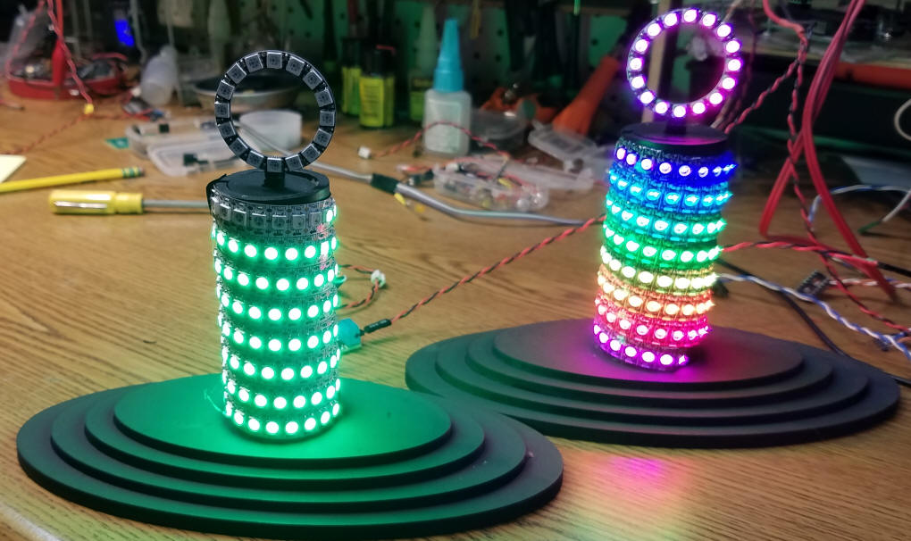
|
| Conclusion I think that you will agree that the tube of LEDs with the circle on top makes an interesting and attention grabbing display. The number of patterns that can be programmed is only limited by your imagination. Please drop me an email and let me know what you come up with. dave@davebodnar.com |