Timers for Model Railroad Applications
Part I
revised
01-24-10 d. bodnar
| Where and how would a hobbyist use a timer on a model railroad?
Can a timer be customized to operate an animation in a specific way?
Can a timer be used to automatically stop & start trains at a
station? How can I use a timer to automate the operation of a
train exhibit? What kind of timers are available that might be
appropriate for model railroad use? I have a unique timing
requirement and have not been able to find a commercial timer that can accommodate
my needs. Can I
build and program my own timer to solve this problem? These questions and more will be answered as we explore timers that can be used to control the behavior of our trains and to provide animation on our layouts. |
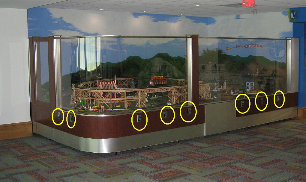
Timers are used in many different model railroad applications. When the Pittsburgh Garden Railway Society installed a model train layout at Pittsburgh's Children's Hospital we employed nearly a dozen separate timers. The layout includes a number of animations, sound effects, a train and a trolley. Each of these are individually controlled by one of the eight pushbutton switches that are found on the base of the platform (see yellow circles below).
When a child presses the button for the main train line a station announcement is heard to say "Train leaving on track one - All Aboard!" and, after a brief pause, the locomotive and cars pull out of the station. The train does a few loops of the layout before coming to rest at the station. A timer is employed to trigger the station announcement and pause a few seconds before activating the train. Another timer determines how long the train circles the layout and plays a role in assuring that it stops at the station at the end of every trip.
Similarly the Mr. Rogers trolley, which can be seen on the trestle in the photo, runs back and forth on its point-to-point track for a few minutes before a timer triggers the controller to return it to its primary station at the far end of the route. The animations and sound effects that are sprinkled throughout the layout run when the appropriate button is pressed and continue to operate for a length of time based on each timer's settings.
There are many, many things that we can automate & animate on our railroads. A timer can be utilized with most of them to determine how long and in what manner they operate.
A Very Basic Timer Kit
A basic timer can be put together in an evening from
a single chip, the 555 timer, a relay, and a few other components. Schematics
abound for various 555 circuits and a number of kits are available, too.
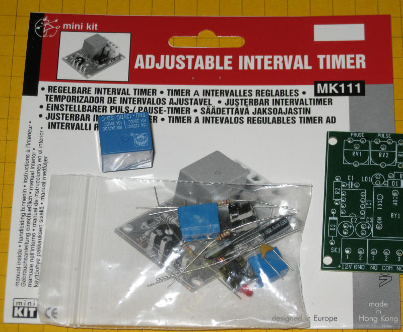
The photos below shows a 555 timer kit that is available from
All Electronics for less than $10.00.
All of the parts and the circuit board to build the timer are in the kit.
In addition you need a soldering iron and a few simple tools..
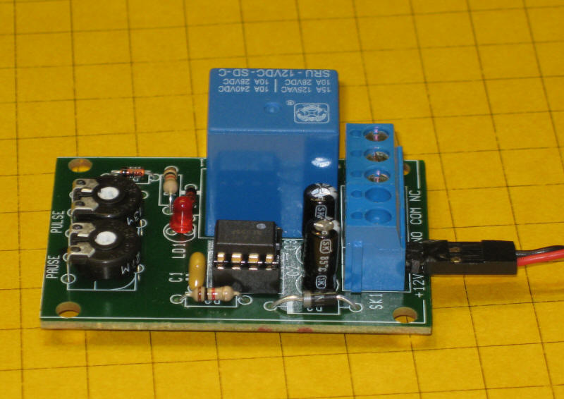
Here is the finished unit. 12 volts goes into the circuit via the
terminals on the right. The terminal block also has connections from the relay's
contacts. The potentiometers (pots) that adjust the pause and pulse time are at
the left. The 555 timer chip is the black device in the socket at the
center of the board.
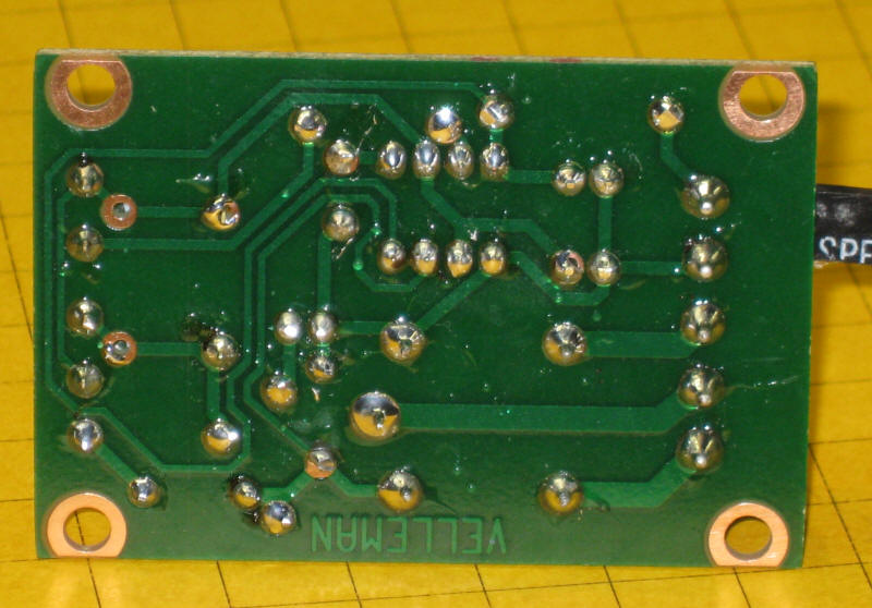
Soldering is done on the back of the board
When power is applied to this circuit the relay closes and stays closed for 0.5 to 5 seconds. After that time expires the relay opens its contacts and pauses for between 2.5 and 60 seconds after which the cycle repeats. The board has two potentiometers on it (the round black items at the bottom of the circuit board). One sets the amount of time that the relay (the large blue object) stays closed and the other determines how long the circuit pauses before the relay closes again.
This continuously repeating cycle of open relay / closed relay may be appropriate for some model railroad operations but not all. Most applications need a timer controlled relay that closes when a switch is triggered with the relay staying closed for a set time before the it opens its contacts and awaits another switch closure. This is the type of timer that was used throughout the Children's Hospital layout.
Industrial Timer: "Omron H3CA"
Of course, we can go to the other extreme and
purchase a commercial timer like the
Omron H3CA that sells for more than $100.00 at
www.Digikey.com .
This timer comes in a variety of versions and is frequently used for
industrial controls. An Omron H3CA was used on the original
Children's Hospital train layout. When a visitor pressed a button
on the front of the layout it activated the timer, turning on the AC power to
the
train's power supply for 50 seconds. When the time expired the
train stopped until the button was pressed again. Simple, but
bullet-proof train control!
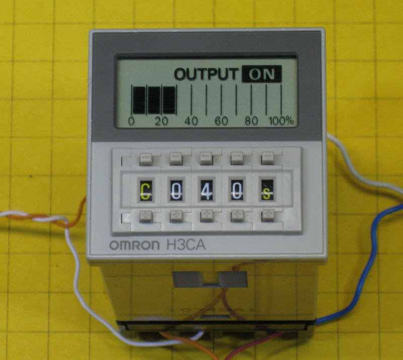
The H3CA has a number of modes of operation that are identified by the first character in its control panel, a letter from A to H. For most applications modes "C" or "D" are appropriate. The other options are spelled out in great detail in the timer's datasheet.
In mode "C" the timer is set to a time that can range from a fraction of a second to 9990 hours (about 416 days!). This is done by selecting a number from "000" to "999" and a Time Unit from 0.1 seconds to 10 hours. If you entered 040 for the time and "s" for the time unit the timer would activate for 40 seconds. If you changed the units to "m" it would activate for 40 minutes. Similarly if you chose "h" it would activate for 40 hours. The time unit options are detailed in the datasheet.
When a pushbutton (or reed) switch connects the "start" terminal the timer's internal relay is closed and stays closed until the time that was selected expires. A graphic display shows the percentage of time remaining. When time is up the relay opens and stays open until the start button is hit again.. The relay is a SPDT unit that has three contacts: a common, a normally open and a normally closed.
This photo shows the Omron timer set to mode "C" and to a time of "040" seconds. The display pictured here shows that the timer is ON and about 30 % of the time remains until it opens the relay contacts. If you look closely at the small buttons above and below the letter "C" and the other characters you will see a small + or - button. These are used to change the value of each item.
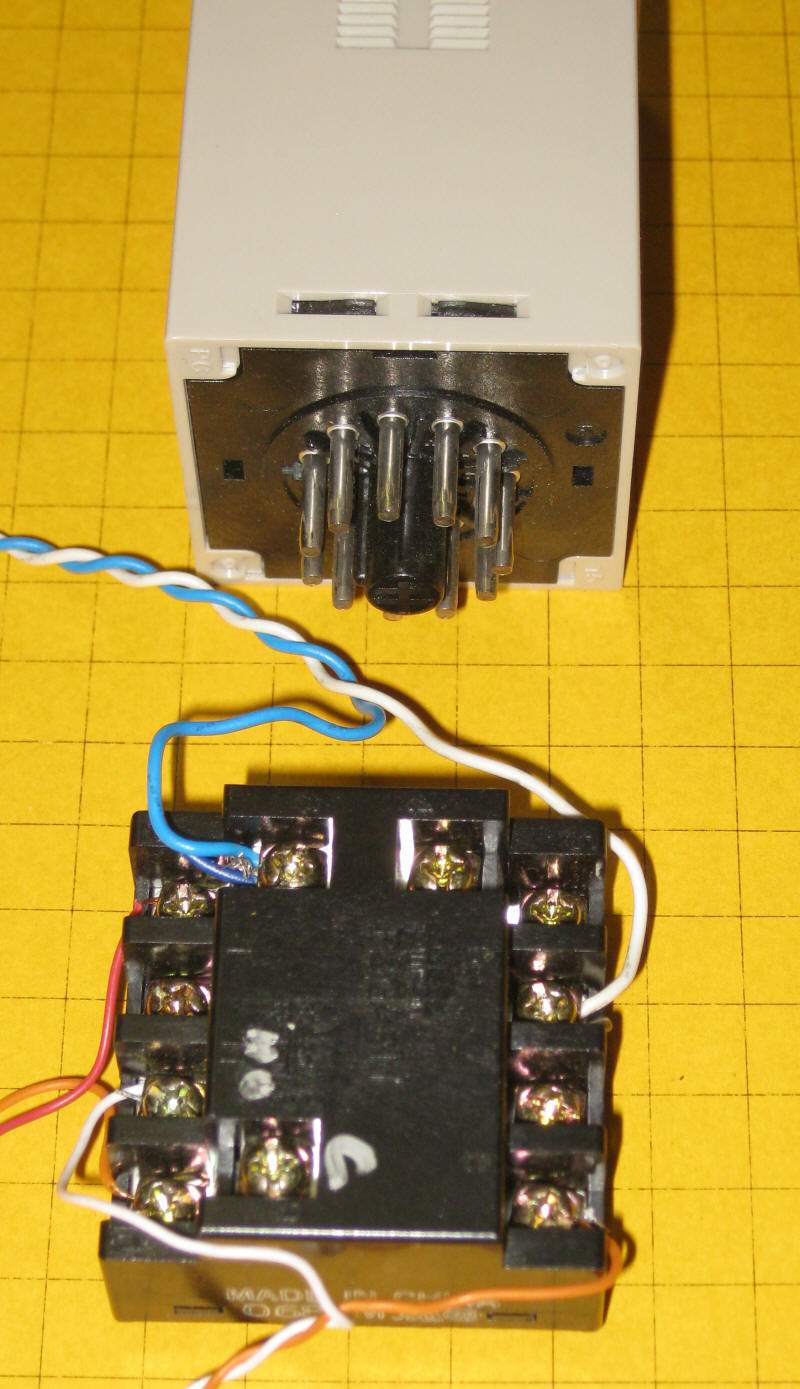
The timer is designed to plug into a socket and has 11 contacts on its base.
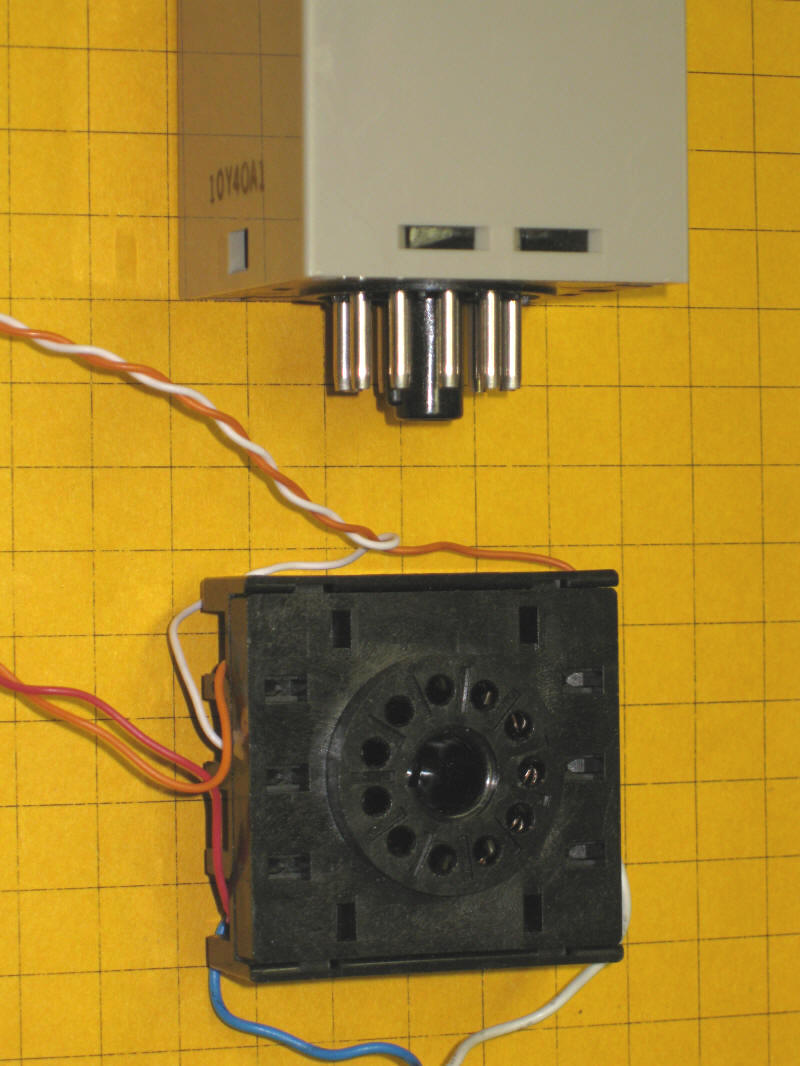
The socket that the unit plugs into has screw terminals on its edge.
Here we see an H3CA that is in a box that has its connection terminals brought out to the top. The timer shows mode "D", which operates in almost the same manner as mode "C", and a time of "060" seconds. The timer is on and about 50% of the time has passed.
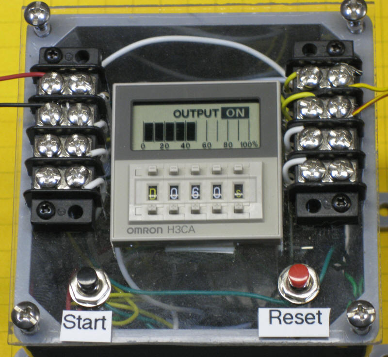
Another train layout that the PGRS built for Phipps Conservatory and Botanical Gardens had three separate loops that were controlled by three Omron timers. Here is the controller that operated that layout.
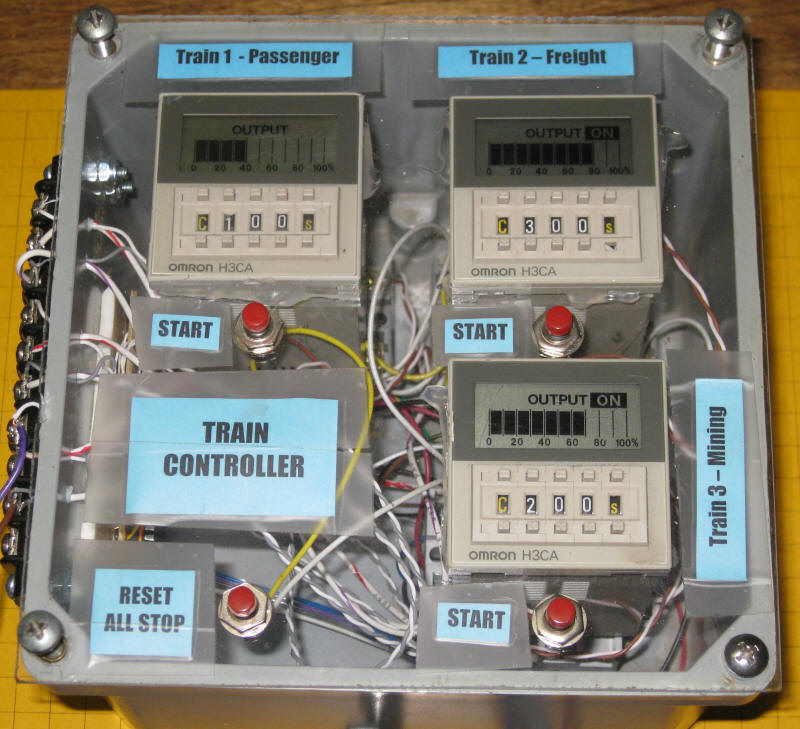
For more information on how this set of timers is wired see: http://pittsburghgardentrains.com/Phipps_2007/Controls.htm
Custom Timer Circuit
Somewhere in between the two extremes in terms of price and well beyond either
in capability is a custom timer circuit that is based on a PICAXE or PIC
microcontroller. This will be the topic of discussion in
part II of this article.