Servo Kit Assembly
d. bodnar 9-19-12 & 9-16-15
New! Click here for software modifications!
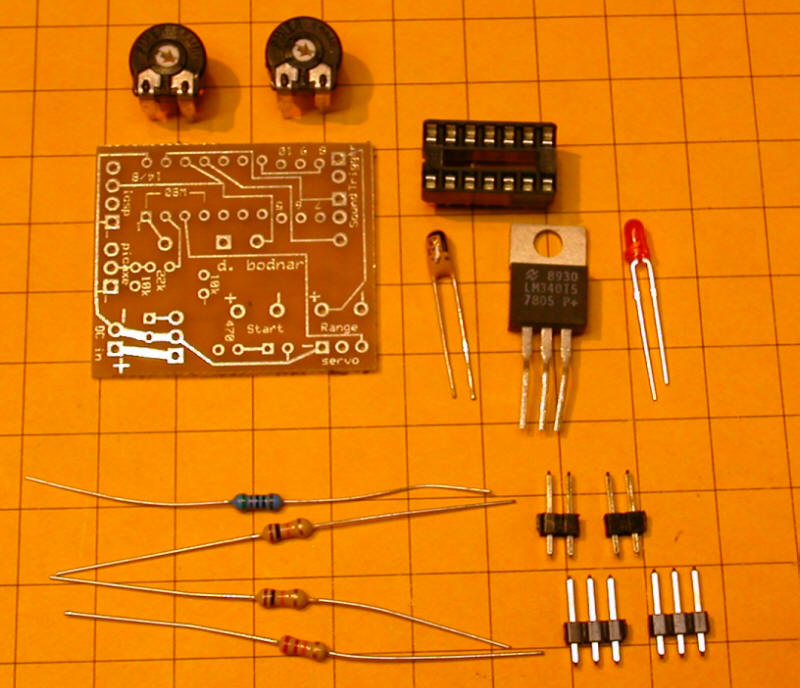
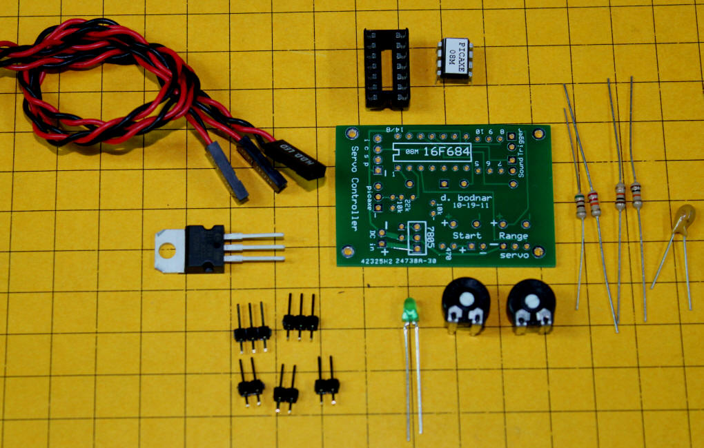
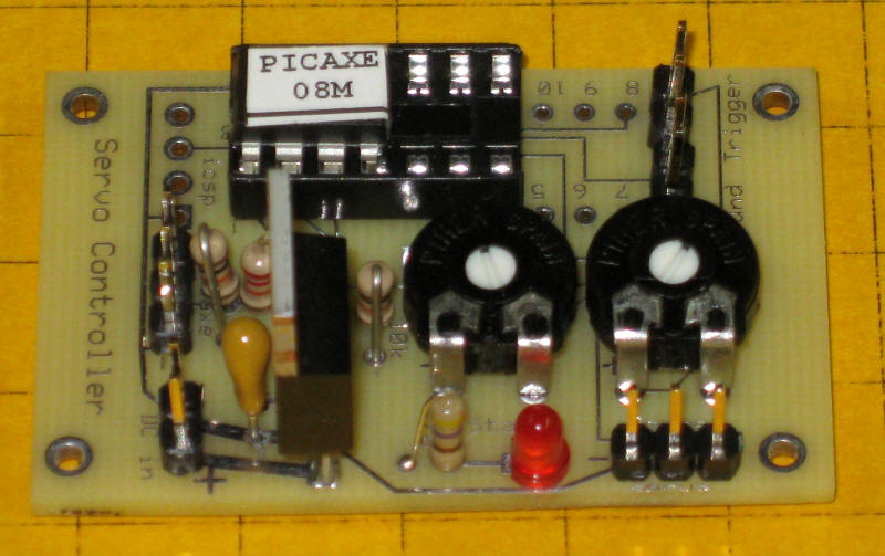
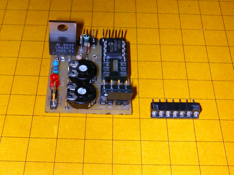
The following parts are needed to assemble the servo controller.
This is the board for the newer revision. Construction is the same.
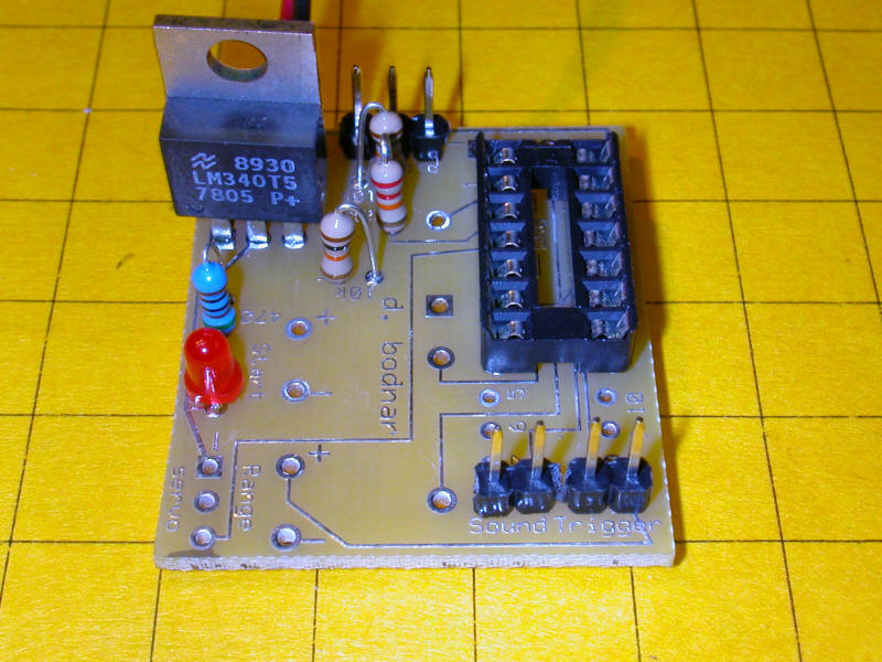
Step 1: Assemble the power supply.
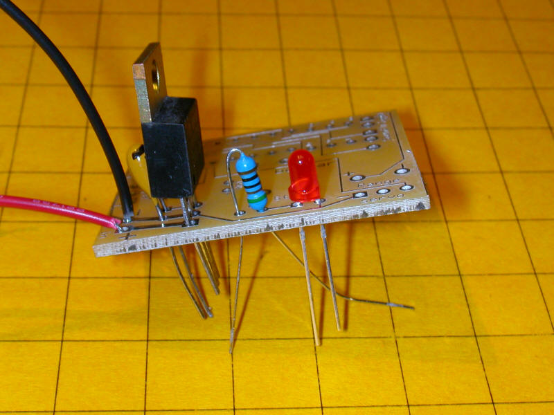
Solder carefully watching out for solder bridges - examine frequently with a magnifying glass.
After soldering apply power (8-12 volts DC) to the red and black wires - the red LED should light. If it does not check for proper parts placement and shorts.
Step 3:
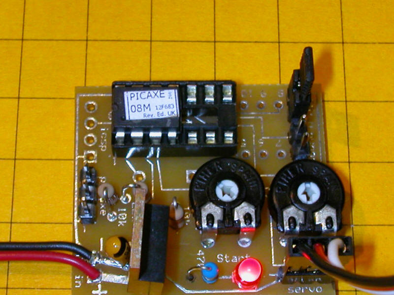
Apply power again and make sure the LED still works.
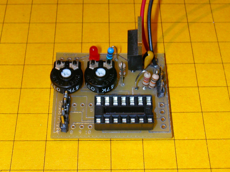
Step 4:
Step 5:
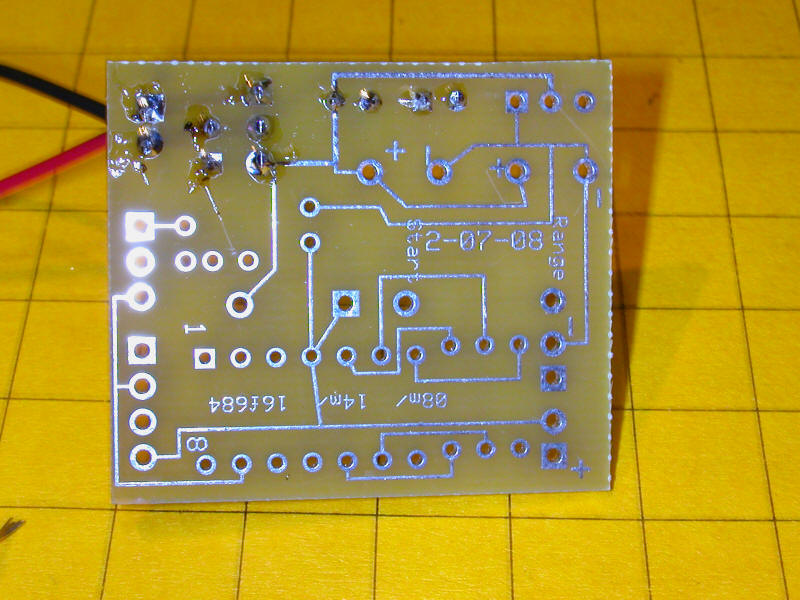
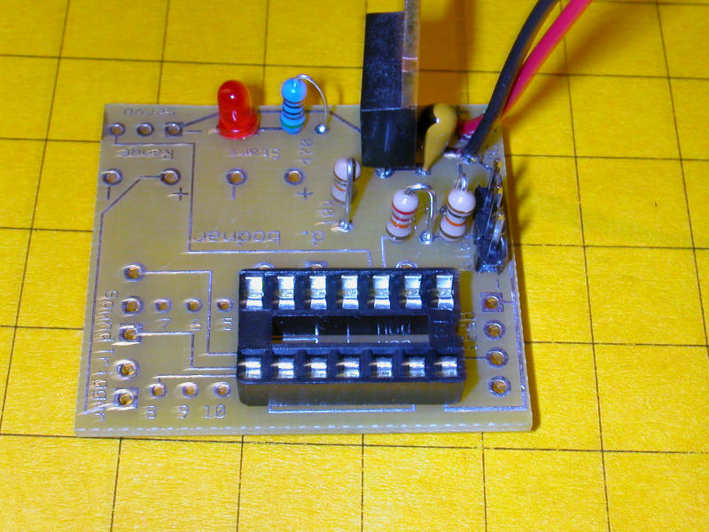
Check the power LED once more. If you have a volt meter confirm that pin 1 on the socket (upper right in the photo above) has 5 volts on it and that lower right pin on the socket is ground. Disconnect power when done.
Step 6:
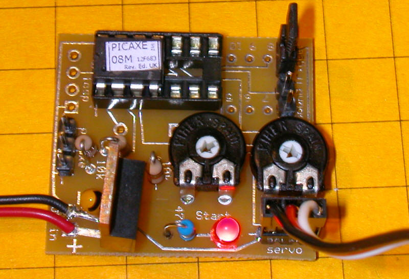
Here is the layout on the newer (8-09) board - note that they are virtually identical except for the mounting holes.
Briefly apply power and confirm that the LED lights properly.
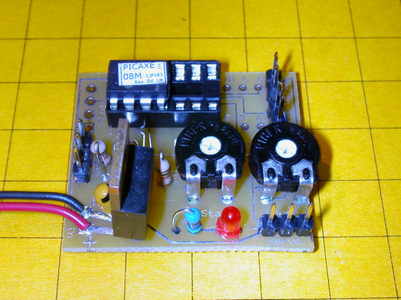
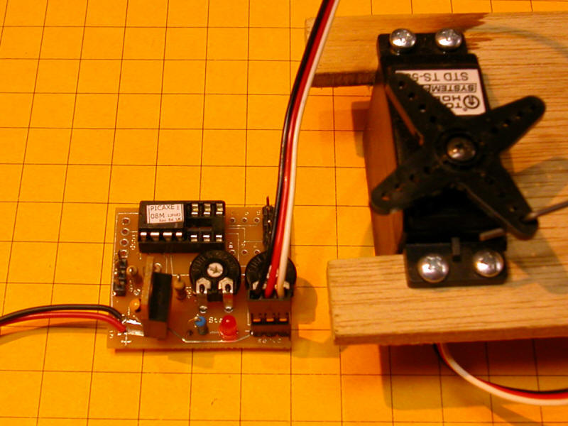
This completes assembly - note that there are a number of unused connections on this board.
Initial Testing:
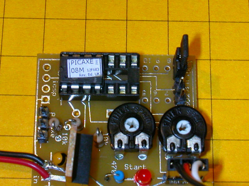
The sound pin (the one closest to the "d" in "Sound") goes "high" for a moment when the trigger is closed. This connection can be used to start a sound card or to light an LED. The other pin in the sound pair goes to ground.
Quick Connectors for Headers
You can salvage connectors from an old PC that will fit right onto the 2 and 3 pin headers on the circuit board. You can also cut up an IC socket into sections that will fit onto the pins. Wires can then be soldered to the socket pins.
.JPG)
| Program
Modifications Some users of the servo board have requested software modifications. Some variations on the original program are shown below with their characteristics. Original program. One button push starts a complete cycle of servo motion from one extreme to the other and back to the original position with a 1.5 second pause between.
|
|
| Modification #1 Objective - in stead of the servo going starting from a button push and going from one extreme of its movement, pausing for a few seconds and returning to its original position two button pushes are needed. The first push has the servo move to its one extreme where it stays till the button is pressed again.
|
|
| Program - revised to use SERVOPOS
command - may reduce "chatter"
SYMBOL CCWMax = 200 '225 manual recommended max |
|
| The code below is not designed to work with
the board in this kit but it does contain some routines that might be
used. It was developed by Kevin Rogers. The program is
designed to lower and raise arms on a crossing and flash crossing lights
when a train crosses one of two light sensors - when the 2nd light
sensor is crossed the crossing arms raise and the flashing stops. start0: #PICAXE 14M2 ;Define Outputs use portB pins SYMBOL Light1 = b.1 'pin 12 SYMBOL Light2 = b.2 'pin 11 SYMBOL Light3 = b.3 'pin 10 SYMBOL Gong = b.4 'pin 9 SYMBOL boom1 = b.5 'pin 8
;Define inputs use portC pins SYMBOL LDR_1 = c.0 'pin 7 SYMBOL LDR_2 = c.4 'pin 3
'Define variables SYMBOL boompositn = b1 SYMBOL currentpos = b2 SYMBOL Flasherflag = b3 SYMBOL Lightlevel1 = b5 ; select a spare variable b5 here SYMBOL LightLevel2 = b6
;define constants SYMBOL BoomSpDelay = 60 'ms SYMBOL FlashDelay = 500 'ms SYMBOL Setpoint1 = 60 ; 0 to 255 is ADC input range - this is the trigger level for lights to flash SYMBOL Setpoint2 = 60 ; 0 to 255 is ADC input range - this is the trigger level for lights to flash SYMBOL BoomIsUp = 120 SYMBOL BoomIsDown = 218 ; first code section is for boom control init: servo boom1,120 ; initialize servo currentpos = BoomIsUp
BoomCtrl: READADC LDR_1, LightLevel1 ; check light level at side 1 READADC LDR_2, LightLevel2 ; check light level at side 2
IF currentpos = BoomIsUp THEN IF LightLevel1 > Setpoint1 OR LightLevel2 > Setpoint2 THEN ; if train is detected at either sensor
ENDIF ENDIF
IF currentpos = BoomIsDown THEN IF LightLevel1 < Setpoint1 AND LightLevel2 < Setpoint2 THEN ; if train is clear of both sensors
ENDIF ENDIF
GOTO BoomCtrl
;============================= ; run the flashing lights as a separate process Start1: LOW Light1 ; turn off all lights and bell/gong LOW Light2 low Light3 LOW Gong LightCtrl: IF LightLevel1 > Setpoint1 OR LightLevel2 > Setpoint2 THEN ; start flashing the lights as boom about to be lowered DO
HIGH Light1
Flasherflag = 4 ; any non zero value - to flag not to repeat
LOOP UNTIL LightLevel1 < Setpoint1 AND LightLevel2 < Setpoint2 AND currentpos = BoomIsUp ENDIF
IF Flasherflag = 4 THEN ; when the boom is fully raised FOR Flasherflag = 4 to 1 step -1 ; flash lights for a few more cycles after the boom is down
NEXT Flasherflag ; on exit b3 = 0 ready for the next cycle
LOW Light1 ; turn off all lights LOW Light2 LOW Light3 ENDIF GOTO LightCtrl
|