Overview & Objective I have built a number of clocks over the past few years. The one thing that most of them have in common is a mechanism that allows them to set themselves rather than depending on me to set them and an internal oscillator to keep them set to the right time. Up to now, all of those clocks depended on a WiFi network connection to get the current time. While this is a wonderful way to get a clock to be accurate it requires a WiFi system and you must put the wireless SSID and password in the clock's code so that they can attach to the Internet and access a time server. With this in mind I decided to experiment with another way of setting the time. As you may know the GPS system of satellites broadcasts a great deal of data that is received and synthesized by your GPS receiver. One of the things that the GPS must have is an extremely accurate time base. This data can be collected by a microcontroller, like the Arduino, and used to drive a clock. This project is a simple implementation that is designed to show how this capacity can be added to your projects. |
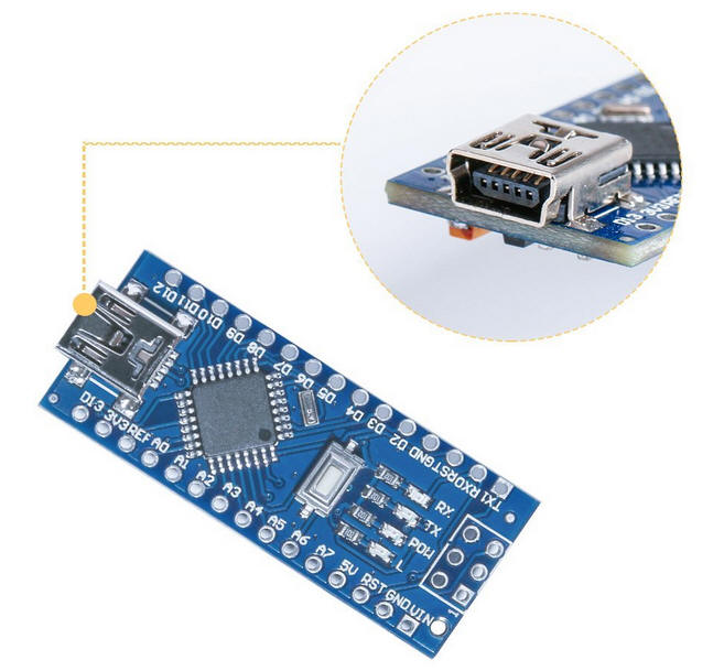
Parts There are three primary components that make up this project: 1. Arduino - just about any will do - I
used a
Nano for its size and built-in USB port.
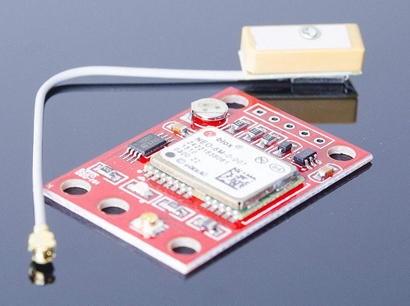
For an even smaller unit the Pro Mini will work, too. 2. GPS Receiver - The unit used is
available from
Amazon and
eBay - any Arduino compatible GPS with serial TX and RX
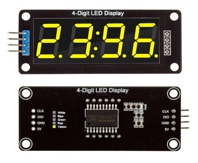
should work 3. LED Display - Any display that uses
the TM1637 controller should work -
the ones that I used are available from
Amazon and
eBay.
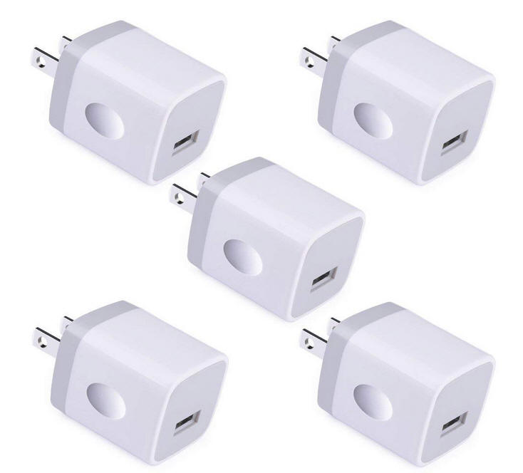
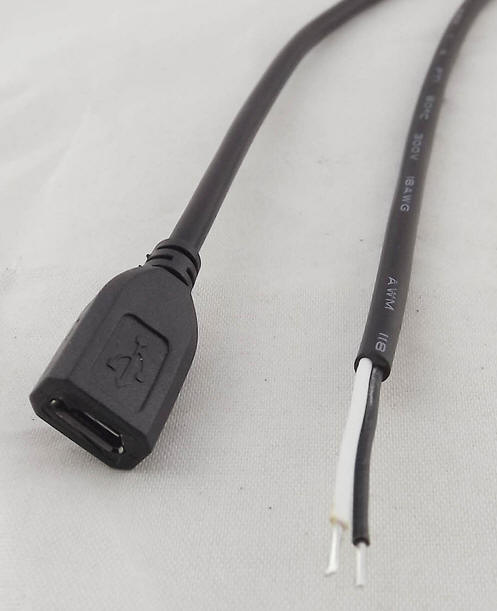
In addition you will need a 5 volt power supply. I used a unit from Amazon. The power was delivered by a micro-USB cable that connected to a micro-USB female cable |
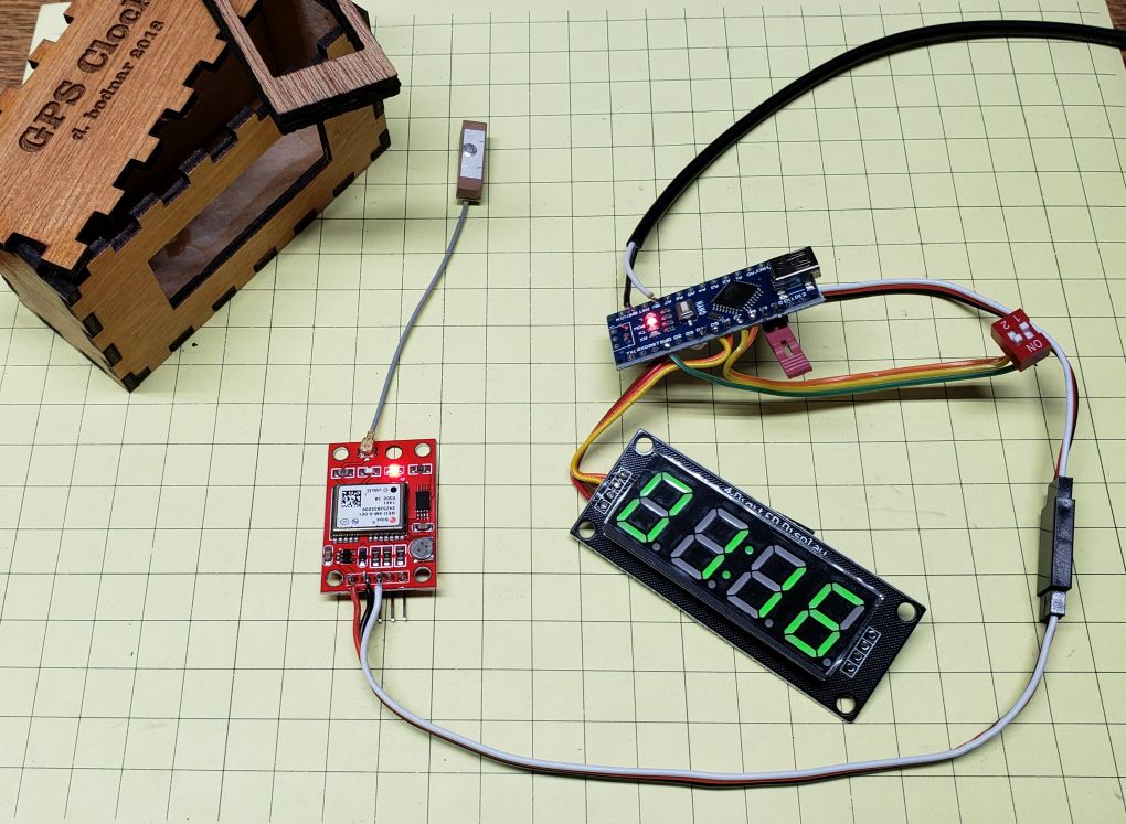
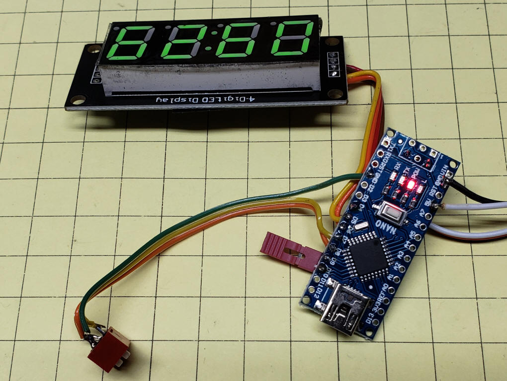
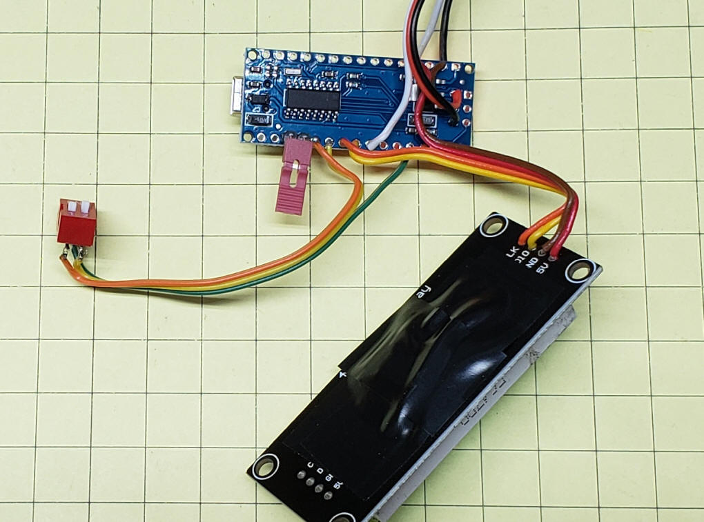
Schematic & Wiring The wiring is straight-forward. I chose to do point-to-point wiring to make the connecting wires as short as possible. |
Wiring These photos show the simple wiring. Please note that the schematic is for an Arduino Pro Mini and the prototype I used is utilizing an Arduino Nano. The pin connections are identical.
|
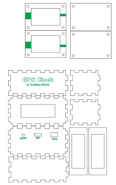
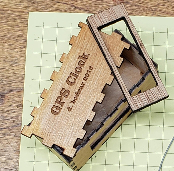
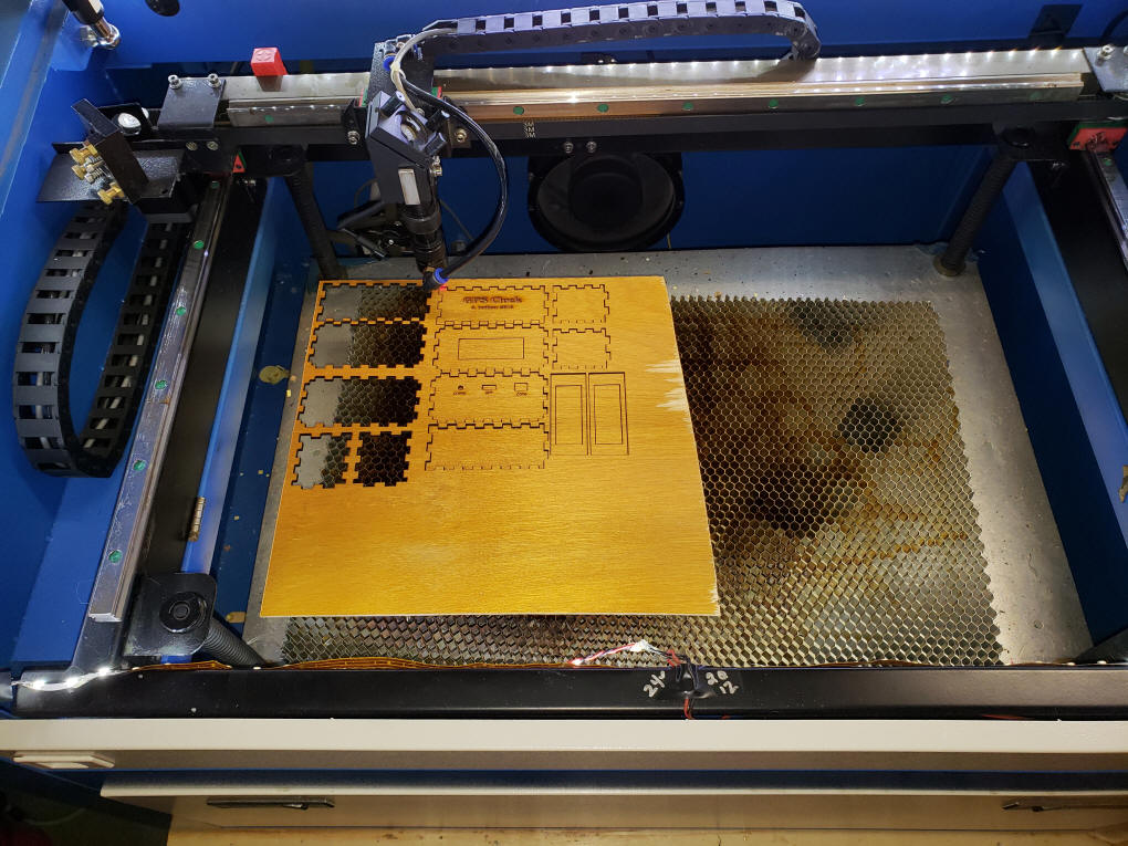
Laser Cut Case The case was designed in CorelDraw and cut on my 50 watt laser cutter. The material for the box (lower six pieces ) is 1/8" plywood. The top part is made from acrylic and encases the GPS unit itself.
This photo shows the parts for the case after they have been cut.
|
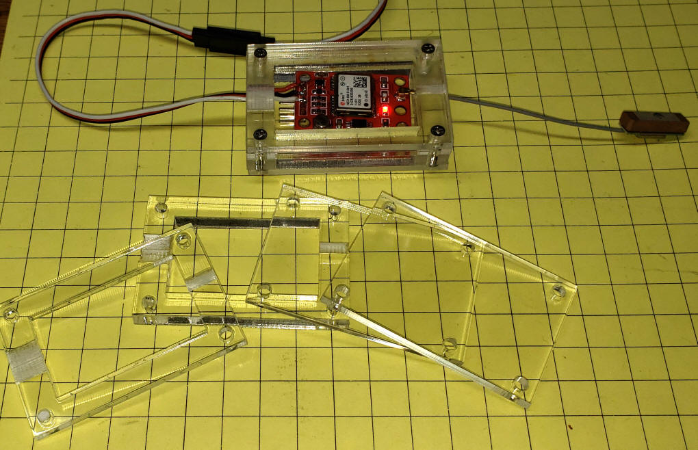
The case for the GPS module is made up of
four pieces of acrylic, one 1/4" and three 1/8" thick. The two
inner pieces are etched a bit to allow the antenna and connection
cables to exit the GPS. I used 3 wire servo cables to connect
the GPS and the Arduino. These cables are readily available
(from
Amazon and
eBay) and can easily be extended if
you need to place the GPS unit near a window so that it can pick up
satellites.
|
Jumpers There are three switches (actually two switches and one jumper) that can be used to modify the behavior of the clock. There is a place for a jumper on pins 9 and 10. If the jumper is installed the clock is in 12 hour mode, if it is removed it is in 24 hour mode. There are two SPST switches connected to pins 7 and 8. These switches select either Eastern Standard Time, Eastern Daylight Time or UTC time. These time zone values can be changed in the code. if
(SW1 == LOW) DSTEST = -4; |
Software The code below is an amalgam of several sketches that I used. I am sure that there are better ways to implement what I have done but for now the code works and seems to be stable. There are several libraries that are used: TinyGPS++ --- https://github.com/mikalhart/TinyGPSPlus SoftwareSerial --- should be included in the IDE SevenSegmentTM1637 and SevenSegmentExtended --- https://github.com/bremme/arduino-tm1637
|
VERSION --- GPS-Clock-TM1637-ZONES---v2-3 #include <TinyGPS++.h> #include <SoftwareSerial.h> #include "SevenSegmentTM1637.h" #include "SevenSegmentExtended.h" static const int RXPin = 4, TXPin = 3; static const uint32_t GPSBaud = 9600; TinyGPSPlus gps; SoftwareSerial ss(RXPin, TXPin); const byte PIN_CLK = 6; // define CLK pin (any digital pin) const byte PIN_DIO = 5; // define DIO pin (any digital pin) SevenSegmentExtended display(PIN_CLK, PIN_DIO); int DST = 7; // jumper for Daylight Savings Time ---- leave both open for UTC int EST = 8; // jumper for Standard time ---- leave both open for UTC int Twelve = 9; // jumper for 12 or 24 hour display == ON = 24, OFF = 12 int LowPin = 10; // pin to pull jumber low for 12/24 hour display int LowPin2 = 11; const unsigned int clockSpeed = 1; // 10000; // speed up clock for demo int Satellites = 12; int hours = 0; int minutes = 0; int wasMinute = 99; // used for blanking leading zero int DSTEST = -4; int TwelveTwentyFour = 24; void setup() { Serial.begin(115200); ss.begin(GPSBaud); display.begin(); // initializes the display display.setBacklight(100); // set the brightness to 100 % delay(1000); // wait 1000 ms Serial.println(F("DeviceExample.ino")); Serial.println(F("A simple demonstration of TinyGPS++ with an attached GPS module")); Serial.print(F("Testing TinyGPS++ library v. ")); Serial.println(TinyGPSPlus::libraryVersion()); Serial.println(F("by Mikal Hart")); Serial.println(); hours = 99; minutes = 99; display.printTime(hours, minutes, true); // display time pinMode(DST, INPUT_PULLUP); pinMode(EST, INPUT_PULLUP); pinMode(Twelve, INPUT_PULLUP); pinMode(Satellites, INPUT_PULLUP); pinMode (LowPin, OUTPUT); pinMode (LowPin2, OUTPUT); digitalWrite(LowPin, LOW); digitalWrite(LowPin2, LOW); delay(1000); } void loop() { while (ss.available() > 0) if (gps.encode(ss.read())) displayInfo(); if (millis() > 5000 && gps.charsProcessed() < 10) { Serial.println(F("No GPS detected: check wiring.")); while (true); } } void displayInfo() { int SW5 = digitalRead(Satellites); if (SW5 == LOW) { display.print("Sat="); delay(500); display.clear(); int temp = gps.satellites.value(); Serial.print("temp = "); Serial.println(temp); display.print(gps.satellites.value()); Serial.print("Satellites Seen = "); Serial.println(gps.satellites.value()); // display.print(" x"); delay(1000); } Serial.print(F("Location: ")); if (gps.location.isValid()) { Serial.print(gps.location.lat(), 6); Serial.print(F(",")); Serial.print(gps.location.lng(), 6); } else { Serial.print(F("INVALID")); } Serial.print(F(" Date/Time: ")); if (gps.date.isValid()) { Serial.print(gps.date.month()); Serial.print(F("/")); Serial.print(gps.date.day()); Serial.print(F("/")); Serial.print(gps.date.year()); } else { Serial.print(F("INVALID")); } Serial.print(F(" ")); if (gps.time.isValid()) { if (gps.time.hour() < 10) Serial.print(F("0")); Serial.print(gps.time.hour() - 4); // time ZONE mod Serial.print(F(":")); if (gps.time.minute() < 10) Serial.print(F("0")); Serial.print(gps.time.minute()); Serial.print(F(":")); if (gps.time.second() < 10) Serial.print(F("0")); Serial.print(gps.time.second()); Serial.print(F(".")); if (gps.time.centisecond() < 10) Serial.print(F("0")); Serial.print(gps.time.centisecond()); /////////////////To Clock LED Display///////////////////////////// int hours = gps.time.hour(); int SW1 = digitalRead(DST); int SW2 = digitalRead(EST); int SW3 = digitalRead(Twelve); if (SW1 == LOW) DSTEST = -4; if (SW2 == LOW) DSTEST = -5; if (SW1 == HIGH && SW2 == HIGH) DSTEST = 0; // UTC if (SW3 == LOW) { TwelveTwentyFour = 12; } else { TwelveTwentyFour = 24; } Serial.print(" DST = "); Serial.print(DSTEST); Serial.print (" Twelve24 "); Serial.println(TwelveTwentyFour); int timezonehr = DSTEST; hours = hours + timezonehr; if (hours > TwelveTwentyFour - 1) { hours = hours - TwelveTwentyFour; if (hours == 0) hours = 12; // make sure shows 12 at noon } else { if (hours < 0) { hours = hours + TwelveTwentyFour; } } /////////////////To Clock LED Display///////////////////////////// int minutes = gps.time.minute(); if (minutes != wasMinute) { Serial.print("Hours just before sent to LED "); Serial.println(hours); display.printTime(hours, minutes, false); // display time if ( hours <= 9) { display.print(" "); } wasMinute = minutes; } } else { Serial.print(F("INVALID")); } Serial.println(); } |
$GPBOD - Bearing, origin to destination $GPBWC - Bearing and distance to waypoint, great circle $GPGGA - Global Positioning System Fix Data $GPGLL - Geographic position, latitude / longitude $GPGSA - GPS DOP and active satellites $GPGSV - GPS Satellites in view $GPHDT - Heading, True $GPR00 - List of waypoints in currently active route $GPRMA - Recommended minimum specific Loran-C data $GPRMB - Recommended minimum navigation info $GPRMC - Recommended minimum specific GPS/Transit data $GPRTE - Routes $GPTRF - Transit Fix Data $GPSTN - Multiple Data ID $GPVBW - Dual Ground / Water Speed $GPVTG - Track made good and ground speed $GPWPL - Waypoint location $GPXTE - Cross-track error, Measured $GPZDA - Date & Time