| Introduction A very functional MP3 player can be made from an inexpensive MP3 board and an Arduino. The unit shown here plays MP3 files either sequentially or randomly when a trigger button is pressed. The MP3 files are placed on a micro SD card. They reside in a subdirectory called mp3 and must be named 0000.mp3, 0001.mp3, 0002.mp3, etc. Click here for a file of the MP3's I use for testing. They are for the Defect Detector and were created with the text to speech function in Windows. |
| Schematic
|
| Pin 1 - 5 volts Pin 2 - Arduino txd via 1K resistor Pin 3 - Arduino rxd via 1K resistor Pins 6 & 8 - 8 ohm speaker Pins 4 & 5 - line out (r & l) Pin 7 - ground |
Click
here to download the file below as a ZIPped file.
/*
 d. bodnar
 1-12-15
 Program to test audio files - must be in /mp3 directory with 4 digit names ie:  0001.mp3, 0012.mp3 etc
 Plays each if trigger is jumpered or one at a time if a pushbutton is used
 Set to play all Defect Detector files (31 files)
 Trigger and jumper for random
 */

#include <SoftwareSerial.h>
#include <DFPlayer_Mini_Mp3.h>
#include <Wire.h>
#include <LCD.h>
#include <LiquidCrystal_I2C.h>
#define I2C_ADDR    0x27 // <<----- Add your address here.  Find it from I2C Scanner
#define BACKLIGHT_PIN     3
#define En_pin  2
#define Rw_pin  1
#define Rs_pin  0
#define D4_pin  4
#define D5_pin  5
#define D6_pin  6
#define D7_pin  7
const int buttonPin = 3;     // the number of the pushbutton pin
const int buttonPin2 = 4;    // second button pin
LiquidCrystal_I2C	lcd(I2C_ADDR, En_pin, Rw_pin, Rs_pin, D4_pin, D5_pin, D6_pin, D7_pin);
char buf[12];

int buusyPin = 10;// buusyPin = 10; // sound player busy
int bsy = 0;
int z = 0;

void setup () {
  pinMode(buttonPin, INPUT);
  pinMode(buttonPin2, INPUT);
  Serial.begin (9600);
  // 30 good for unpowered speaker - requires power off to reset volume
  lcd.begin (16, 2); //  <<----- My LCD was 16x2
  lcd.setBacklightPin(BACKLIGHT_PIN, POSITIVE); // Switch on the backlight
  lcd.setBacklight(HIGH);
  lcd.home (); // go home

  lcd.setCursor(0, 0);
  lcd.print("Audio File Test");

  mp3_set_serial (Serial);	//set Serial for DFPlayer-mini mp3 module
  // mp3_reset();
  delay (400);
  mp3_set_volume (25);          // 15 is low for unpowered speaker - had to remove reset to get vol to work
  delay (400);
  Serial.println("");

  Serial.println("play MP3 files in sequence with trigger & random option  v3.1b");

  delay(100); // may be needed for initialization of sound
  randomSeed(analogRead(0));
}

void loop () {
  for (int zz = 1; zz <= 11; zz++)//set max to number of mp3's
  {
    if (digitalRead(buttonPin) == 1) {
    if (digitalRead(buttonPin2) ==1){
    zz=random(1,11);   //set max to number of mp3's
    }
      Serial.print(zz);
      Serial.print(" ");
      lcd.setCursor(0, 1);
      lcd.print("File: ");
      lcd.print(zz);
      lcd.print(" ");
      mp3_play(zz);  //degrees
      dlayPrint();
      delay(100);
    }
  }
}

// routine to stay here till busy pin goes low once then goes high after speech item completes
void dlayPrint()
{
  while (digitalRead(buttonPin) == 1) {  //wait for button to be released
    //delay (100);
  }

  int bsyflag = 0;
  Serial.println(" ");
  Serial.print("busypin ");
  for ( z = 0; z <= 10000; z++) {
    bsy = digitalRead(buusyPin);
    Serial.print(bsy);
    delay(50);
    if (bsyflag == 1 && bsy == 1) {
      break;
    }
    if (digitalRead(buttonPin) == 1) {
      break;
    }
    if (bsy == 0) {
      bsyflag = 1;
    }
  }
  Serial.println(" ");
  Serial.println("done");
}
|
|
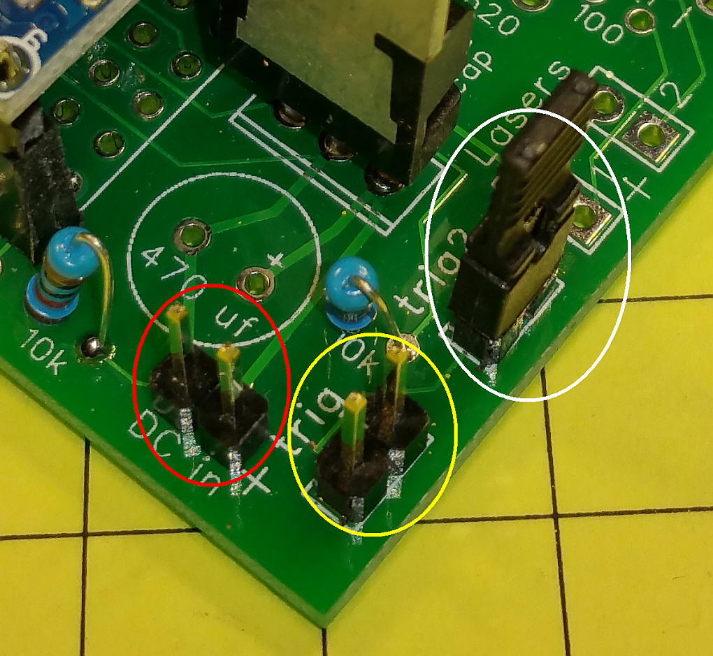
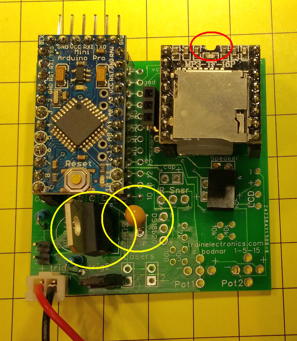
The power connection is circled in red. Make
sure the positive voltage goes to the pin marked "+". The
jumper (circled in white) is on for random or off for sequential.
The trigger switch is connected to Trig, circled in yellow.
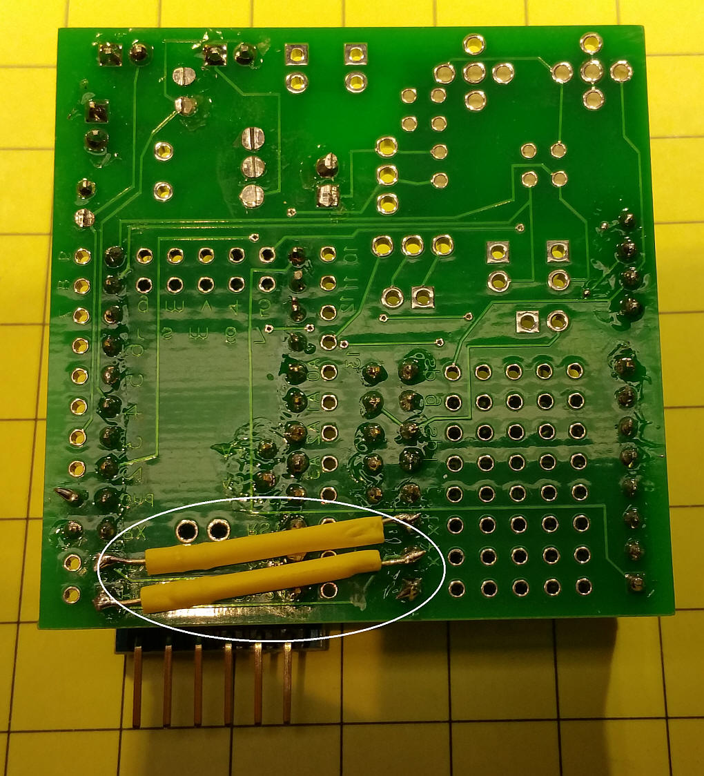
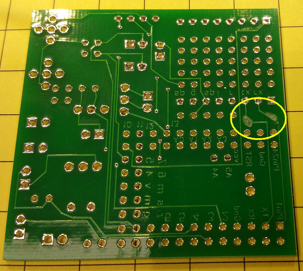
There are 1000 ohm resistors inside of the yellow tubing that connect the TX, RX on the Arduino to the RX, TX on the MP3 module. The traces that originally connected these pins have been cut. See next photo.
The two cut traces are circled in yellow.
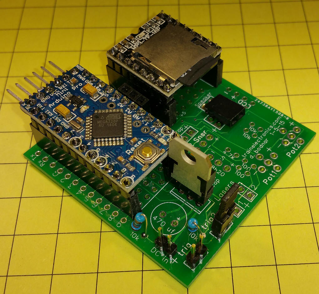
The MP3 module must be inserted with its notch as shown (circled in red). The voltage regulator (3 pin device circled in
yellow) must be inserted as shown. The tantalum capacitor (also
circled in yellow) must have its longer lead (positive) inserted into
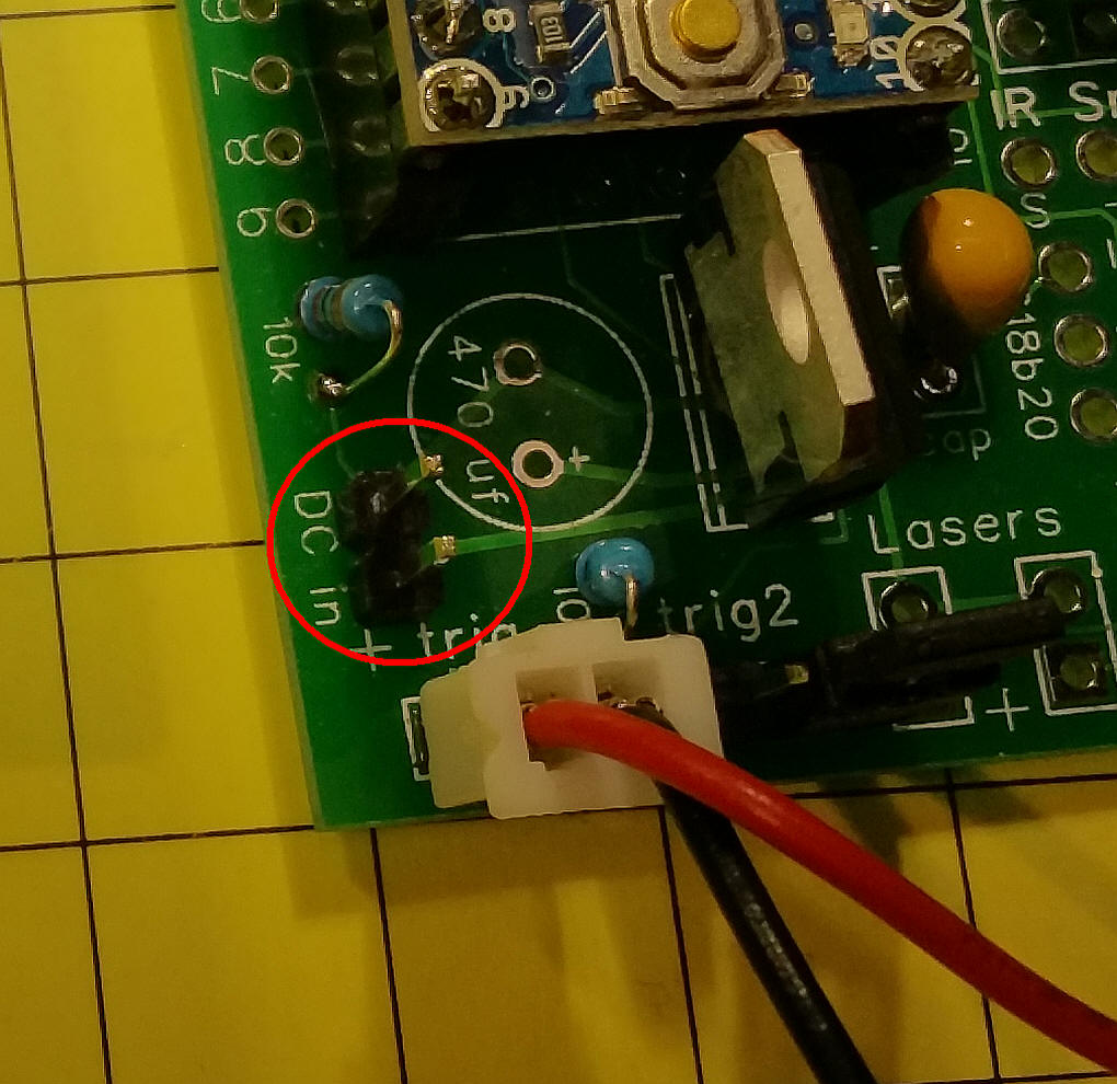
the hole marked with a "+" Power (7 to 12 volts DC) is connected to the two pins shown here (circled in red) - the positive MUST go to "+" or the circuit will be damaged.
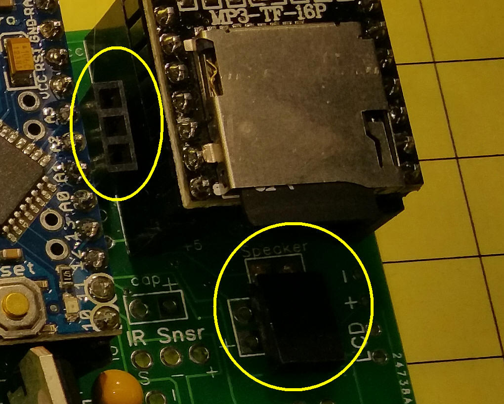
The speaker connects to the two pin header labeled "Speaker" - this is a powered output that will drive a small 8 ohm speaker. The three pin header is for an amplified stereo set of speakers.
|