| Wednesday, August 23 Completed installation and testing
of one of three infrared emitter detector pairs.
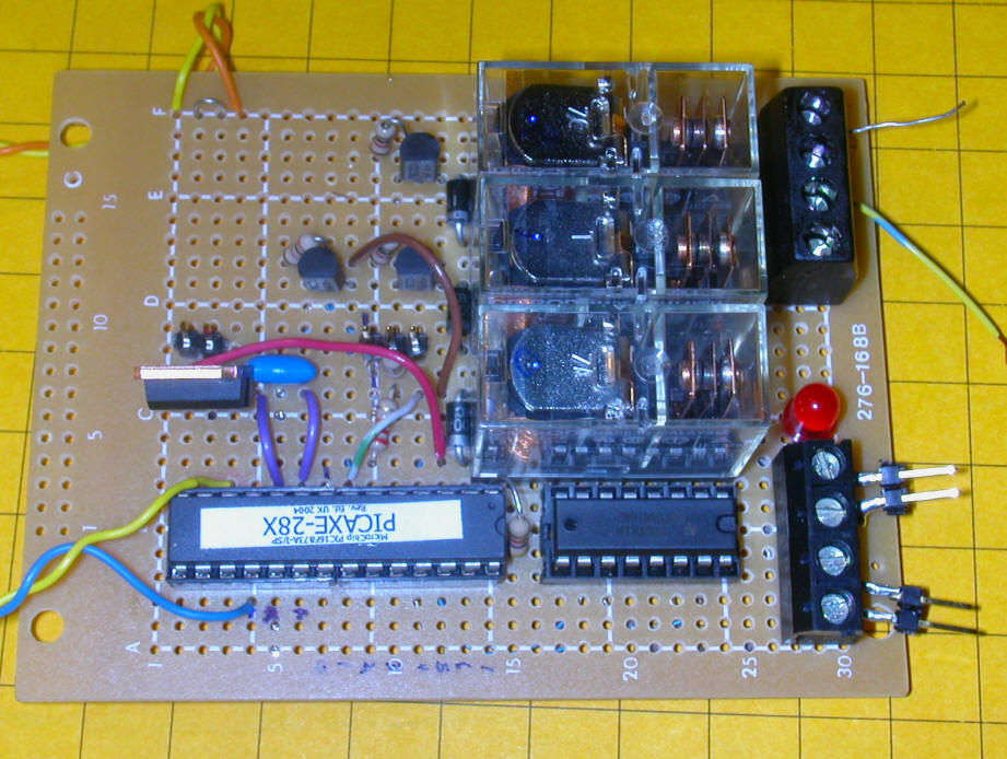
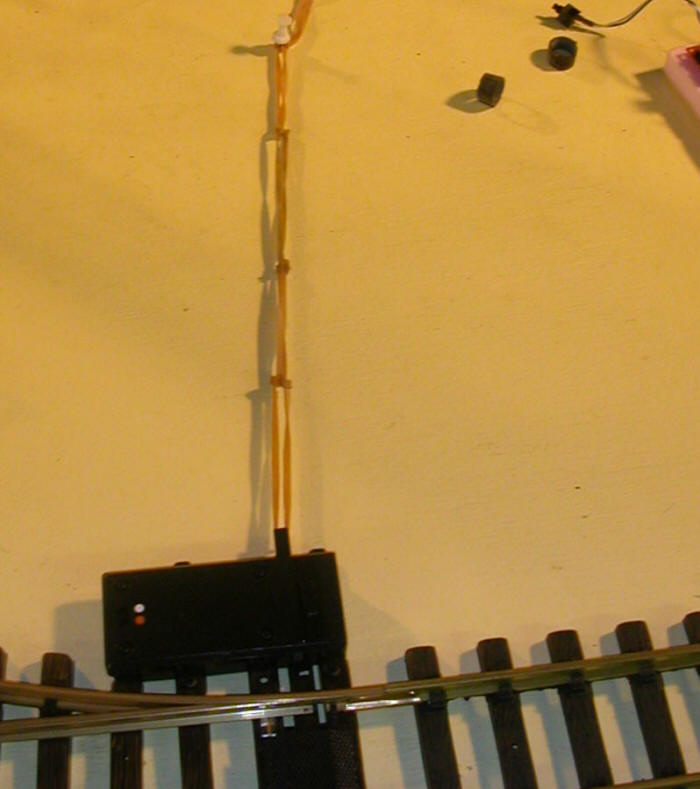
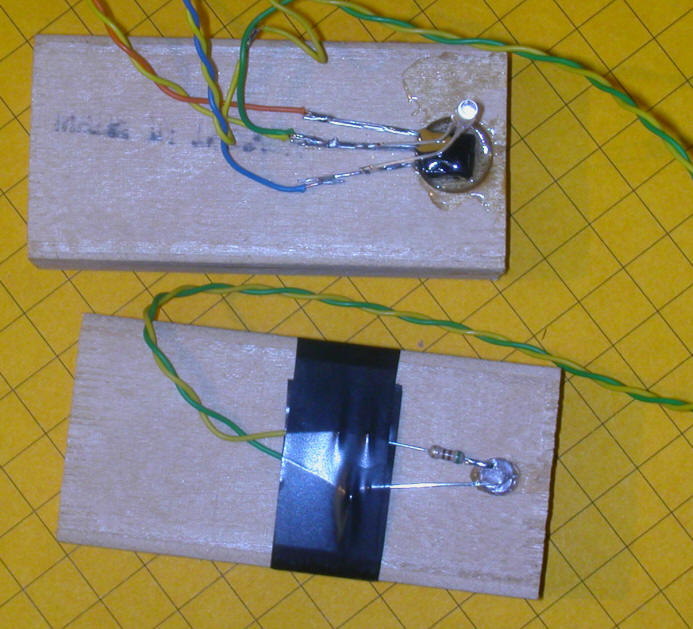
In the photo below the back of the IR detector is shown at the
top. The small clear LED lights when the emitter and detector
pair are NOT properly aligned and goes out when they are aligned.
A four conductor cable goes to each pair. This provides +5
volts, ground, 38 KHz for the LED and an input for the controller
that goes high when the detector sees the IR from the emitter.
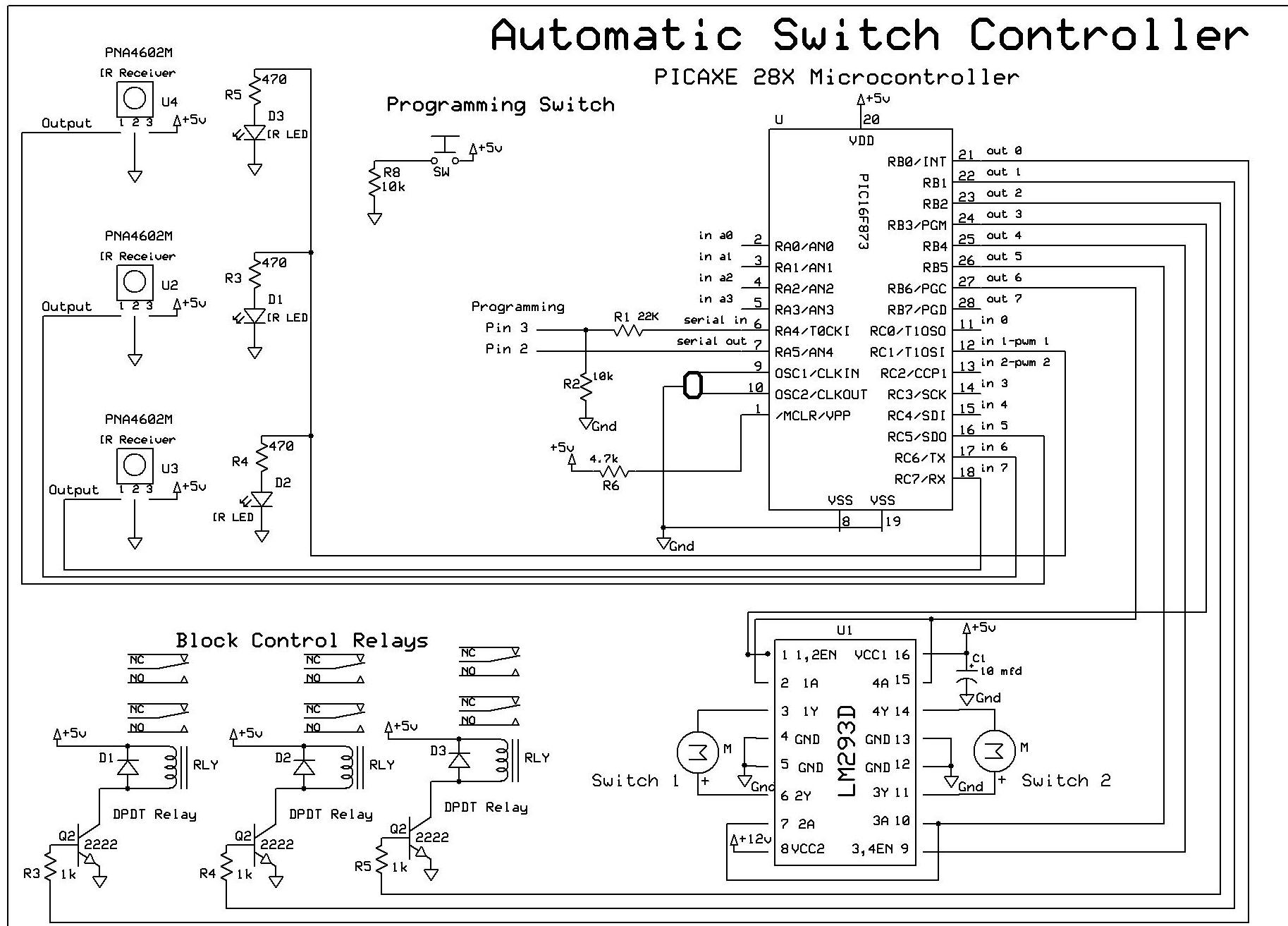
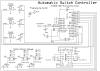
The schematic was revised to include the IR pairs and H-Bridge.
The LCD display was removed as this will be on a separate circuit
board.
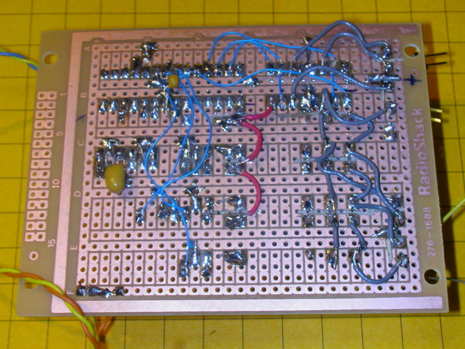
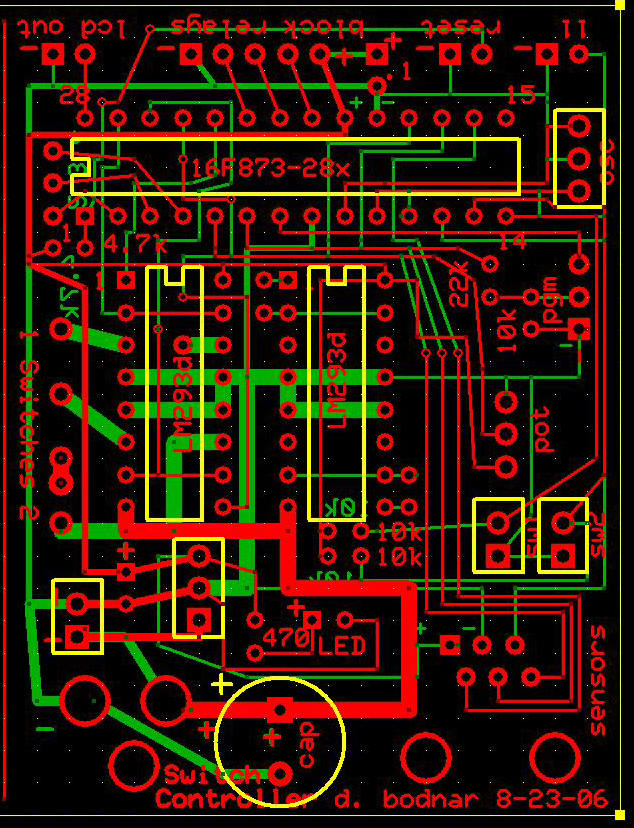
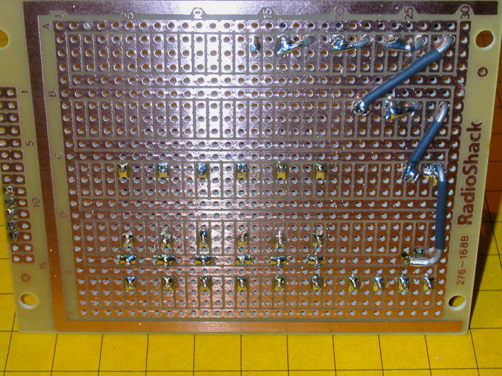
The main task of the day was the design of the printed circuit
board. This was completed and the drawing was sent off to
Oregon to be fabricated. Delivery is scheduled for Monday.
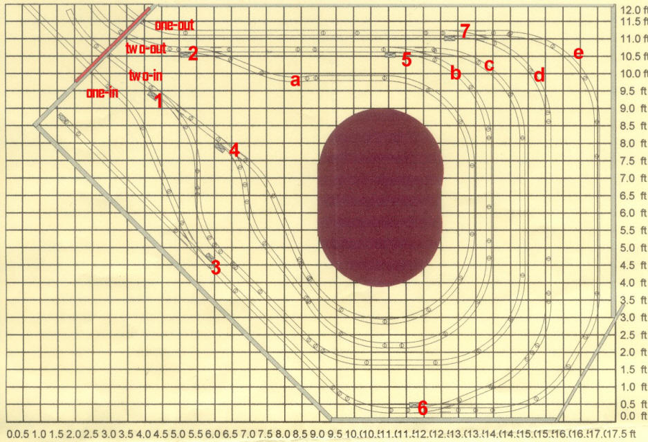
The red layer shows traces that are on the top of the board while
green shows traces on the bottom. The yellow layer will not be
visible on the finished boards.
Notes:
1. Two boards will be built. Even though one of the
controlled loops has 3 sidings & 3 trains while the other has only 2
both boards will be identical and capable of operating 3 trains.
An option in the software setup will determine the number of trains
to be run. Using identical boards will facilitate
troubleshooting and repair as parts can easily be swapped to
determine the root of a problem.
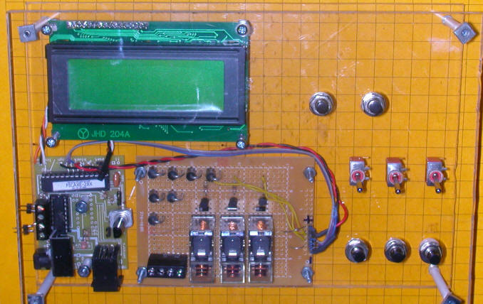
2. The prototype board has the 3 block control relays on the
same board with the H-Bridge and the microcontroller. The
finished system will have the relays located on a separate board.
There will be 5 wires connecting the two boards (+12 volts, ground
and three control leads that will connect to the base lead on the
transistors that activate the relays.)
3. A separate LCD controller will operate the LCD display
unit. Data will be transferred via a two wire serial connection.
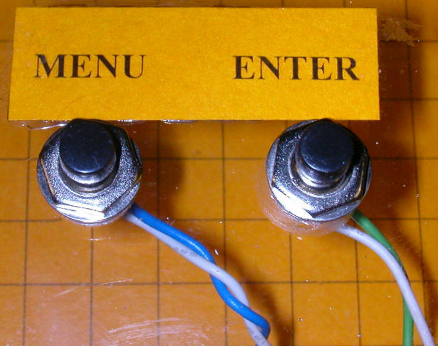
4. Program modifications will be by means of a program switch
and either a potentiometer or an additional switch.
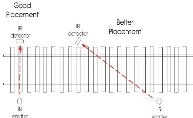
5. The IR emitter / detector pairs will be connected to the
main circuit board through a 6 conductor cable that terminates in an RJ-12
plug / jack pair. Near the detectors this cable will be
separated to provide a connection to each of the three IR units.
Each unit will have a 4 conductor cable going to it with +5 volts,
ground, 38 KHz pulses for the LED and an input line (the only unique
connection to each unit) that goes from
the sensor to the main board.
6. Each block (siding) will be insulated at both ends on only
one rail. One insulator will be bypassed by the relay that
controls it. When the relay is open the block will not
have power. One wire from the constantly "hot" part of the
loop goes to the common contact of each relay. The normally
open contact from each relay goes to the block that it controls. |
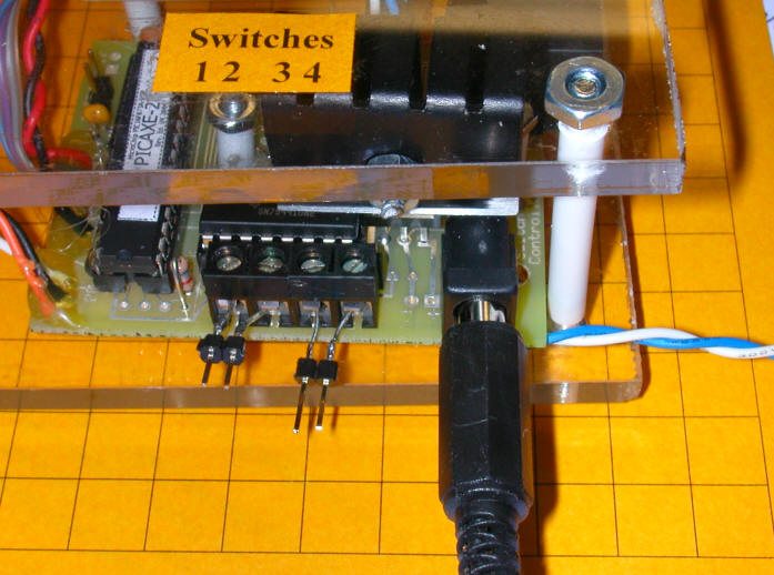
| Tuesday, August 29
The next major project was to complete the design and construction
of the relay / block control boards. These boards are
interfaced to the main processor board by a five conductor cable
that delivers +12 volts for the relays, ground and three control
signals that activate any of the three block control relays.
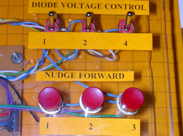
In addition to the three relays there are seven diodes is three
groups, 1, 2 and 4 diodes each. SPDT toggle switches can put
any, all or none of the diodes in series with the track voltage,
dropping the voltage to the blocks up to nearly 5 volts in .7 volt
increments.
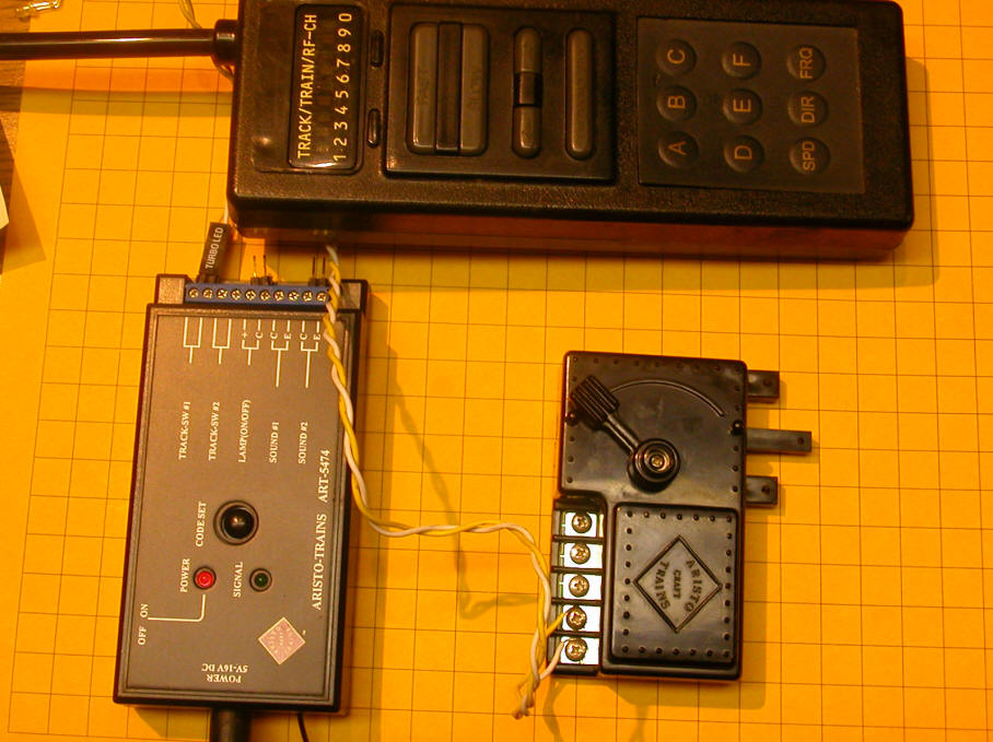
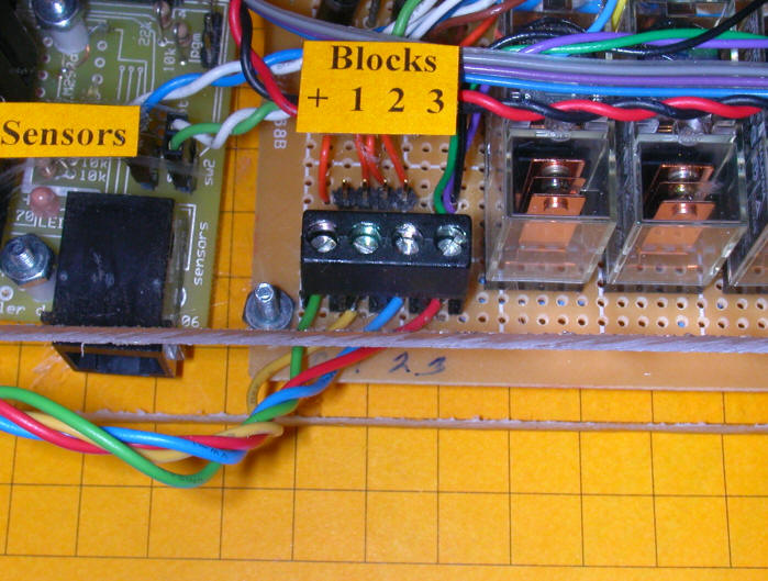
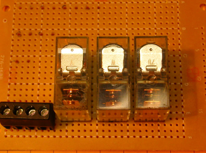
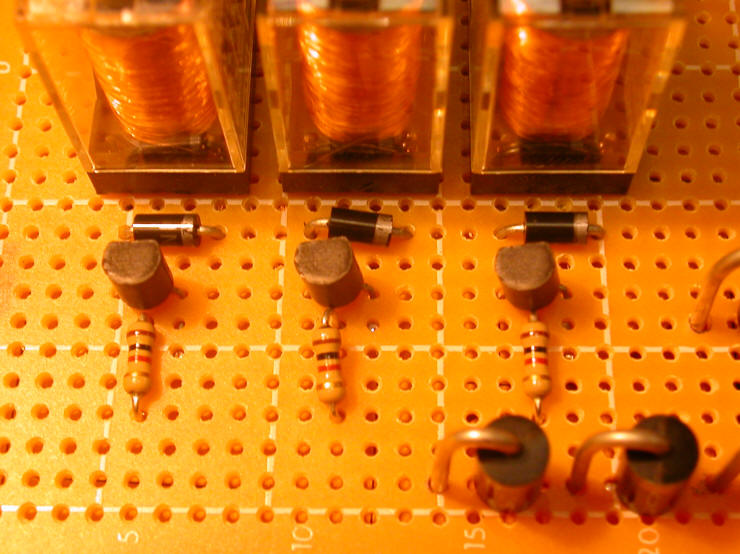
Here you see the three relays and the 4 pole header that will
connect to the blocks. Also note the marks on the board
in the upper left corner. They indicate where the voltage
control diodes will be placed.
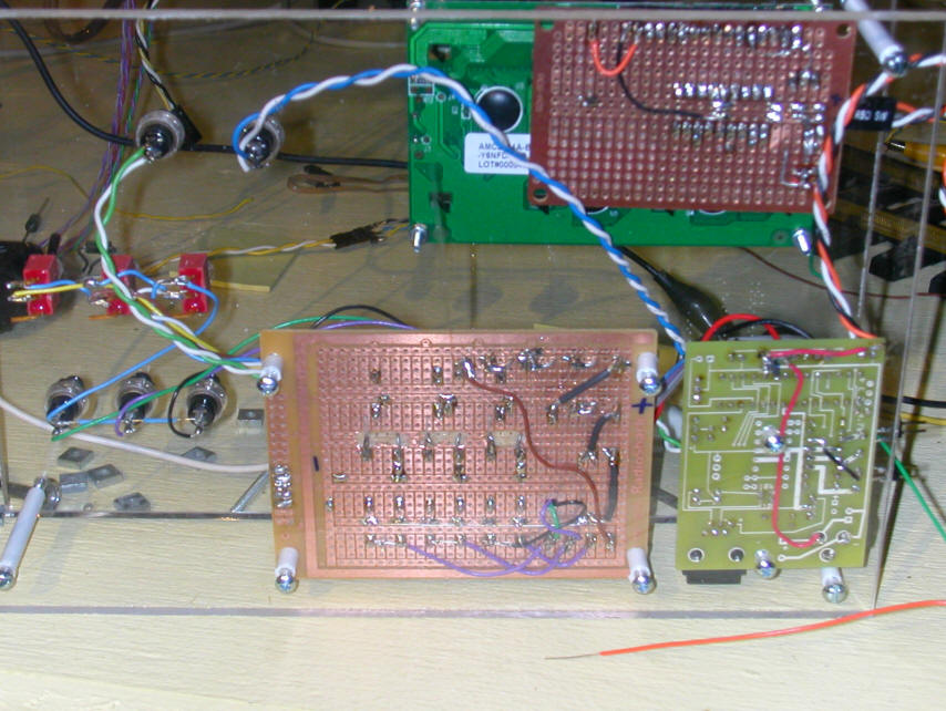
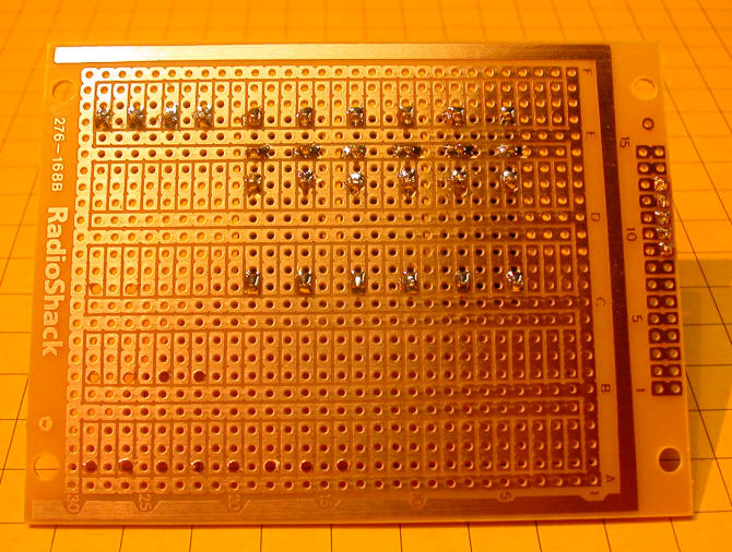
Here the same board is seen from the back with the header and
relays soldered in. The holes for the 3 amp diodes have been
drilled out so that their larger leads will fit.
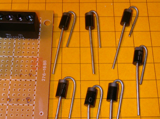
The diode leads are bent so that they can be
inserted vertically.
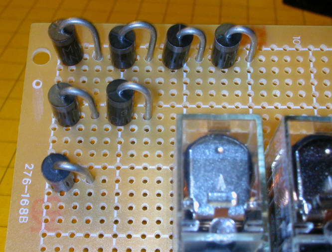
The diodes have been inserted in the board so that
they can be wired in series.
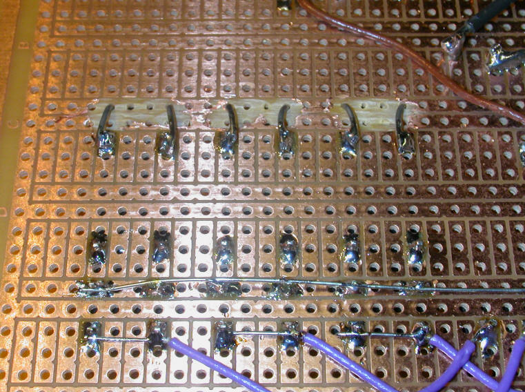
Here is a view of the diodes as soldered to the
back.
Each relay is connected to a diode, to protect the
circuit from voltage surges when it is in operation, and a
transistor that is used to activate it. The orientation of the
diodes and transistors is critical!
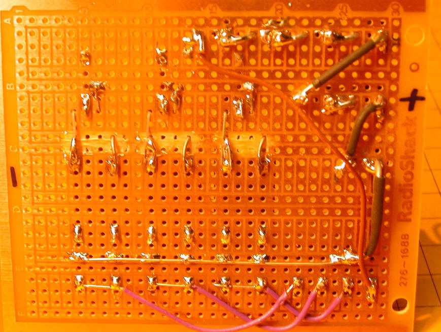
The back of the board shows where some foil needs to
be removed to protect against short circuits where the diodes
connect to the relays.
The additional parts shown here are the transistors
and the resistors that connect to their bases.
|
'd. bodnar 9-4-06
'works with 2 or 3 trains based on value of SensorValue
'problem with intermittent detection of all sensors blocked cured by
turning PWM on/off
'rather than leaving it on constantly
'TODO:
' 1. XXX configure one button to be an "end after all in blocks" and
interface to remote control - may use pin 2 (input port a0)
' ("if porta pin0 = 1 then jump")
' 2. Create menu function - variables to be modified and written to
memory (WRITE location, bytevalue) - 0-127 available on 28x
' a. 3 or 2 engines / blocks
' b. pause time for "nudge" function
' c. fixed order or random (random to allow repeats or no?)
' d. reset counter on power up or keep running count?
' e. time between trains exiting blocks - quick, fixed or random?
' f.
' 3. XXX Menu called up by pressing and holding MENU button on
power-up (Menu on pin 14 (in3))
' a. change data through button or pot (pot set up on pin 5 (an3))
' 4. XXX When "Sensors not Blocked" flashes show which one(s)
(is/are) not blocked
' 5. XXX BUG - when speed is too fast a long car with big spaces (lil
critter & log car) set off sensor like it is back as it leaves
' 6. XXX Stop all blocks when 2 or more sensors not blocked after or
during first and subsequent runs
symbol relay1 = 0
symbol relay2 = 1
symbol relay3 = 2
symbol sensor1 = pin5
symbol sensor2 = pin6
symbol sensor3 = pin7
symbol EnterSw = pin2 'pin 13 on PICAXE - 1 when out, 0 when pushed
symbol MenuSw = pin3 'pin 14 on PICAXE - 1 when out, 0 when pushed
symbol EndSwitch = pin4 'pin 15 on PICAXE - 1 when out, 0 when
pushed
symbol swmotor1 = 3
symbol swmotor2 = 4
symbol swdir1 = 5 'h-bridge
symbol swdir2 = 6 'h-bridge
symbol nextloop = b4
symbol temp0 = b3
symbol temp1 = b5
symbol temp2 = b2
symbol temp3 = b6
symbol tempCL = b7 'temp storage of Current Loop Engine
symbol Laps = w6
symbol EndFlag = bit8
symbol version = 28
symbol dlay = 120
symbol SensorValue = b8
symbol PinsByte = b0 'using b0 allows us to access each sensor bit
with bit5, bit6 & bit7
NextLoop = 0 'use 0-2 in stead of 1-3 for branch statement
'NOTE SensorValue must be set on first run with
MENU!!!!!!!!!!!!!!!!!!!
'SensorValue = %11100000 ' %11100000 for 3 trains and %01100000 for
2 trains
'SensorValue = %01100000 ' %11100000 for 3 trains and %01100000 for
2 trains
read 0, SensorValue
if SensorValue <>%11100000 and SensorValue<>%01100000 then
fixSensorValue
goto NoNeedtoFix
fixSensorValue:
SensorValue=%11100000 'set to 3 trains if read is bad
NoNeedtoFix:
pause 6000 'pause while LCD wakes up and does test display
pause 100
if SensorValue=%11100000 then engines3a
temp0=2:goto skipover1a:
engines3a:
temp0=3
skipover1a:
serout 7, t2400,("?f?c0"):pause 200:serout 7,t2400,("?f?c0"):pause
200 '?c0 turns cursor off
serout 7,T2400,("Switch Controller?nd. bodnar 8-2006?nVersion
",#version," Trains=",#temp0)
serout 7, T2400,("?x00?y3 MENU FOR SETTINGS")
Check4MenuButton:
for temp1=1 to 100
if MenuSw=0 then goto MENU
pause 30
next temp1
serout 7, T2400,("?fResetting Switches")
gosub sw1turn:pause 200:gosub sw2turn:pause 200:gosub
sw1straight:pause 200:gosub sw2straight:pause 400 ' set for initial
run
'pause 4000
Start:
PWMOut 1, 25, 52 ' 38.4 kHz to IR emitters
temp1=pins & SensorValue
PWMOut 1,0,0
if temp1 <> SensorValue then ShowError
serout 7,T2400,("?fSensors All Blocked")
goto start1:
ShowError:
'SensorValue=pins
serout 7,T2400,("?fSensor(s) OPEN ",#temp1)
serout 7,t2400,("?nSensor 1 = ")
temp0= temp1 & %00100000
if temp0=0 then closed1
temp0=temp1 & %00100000
if temp0=1 then open1
open1:serout 7,T2400,("OK"):goto show2
closed1:serout 7,T2400,("open"):goto show2
show2:
serout 7,t2400,("?nSensor 2 = ")
temp0= temp1 & %01000000
if temp0=0 then closed2
temp0= temp1 & %01000000
if temp0=1 then open2
open2:serout 7,T2400,("OK"):goto show3
closed2:serout 7,T2400,("open"):goto show3
show3:
if SensorValue=%01100000 then done:
serout 7,t2400,("?nSensor 3 = ")
temp0=temp1 & %10000000
if temp0=0 then closed3
temp0=temp1 & %10000000
if temp0=0 then open3
open3:serout 7,T2400,("OK"):goto done
closed3:serout 7,T2400,("open"):goto done
done:
pause 500
goto start:
Start1:
endflag=0
serout 7,T2400,("?fAll Trains Ready!?n?nPress ENTER?nto START")
loop:
if EnterSw =1 then loop:
serout 7,T2400,("?f")
Start2:
'serout 7,T2400,("?fnextloop= ",#nextloop)
if endflag=1 then Start1
Branch NextLoop, (one, two, three)
serout 7,T2400,("?fnextloop= ",#nextloop):serout 7,T2400,("?nERROR
FIX ?nPausing 60 seconds"):pause 60000
nextloop=0:goto start2 'error trap - sometimes hung here
end
one:
gosub Sw2Straight:gosub Sw1Straight 'return 1 to 1
high NextLoop 'start train on block # NextLoop +1
goto AddOneToNextLoop
two:
gosub sw1turn:gosub sw2straight 'return 2 to 2
high NextLoop 'start train on block # NextLoop +1
goto AddOneToNextLoop
three:
gosub Sw2Turn
high NextLoop 'start train on block # NextLoop +1
goto AddOneToNextLoop
end
AddOneToNextLoop:
Laps=Laps+1
TempCL=NextLoop 'stores Train Running for possible nudge adjust
below
NextLoop=NextLoop + 1
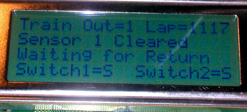
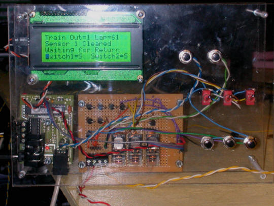
serout 7,T2400,("?x00?y0Train Out=", #NextLoop, " Lap=",#Laps)
serout 7,T2400,("?x00?y1 ?x00?y2 ") 'clear lines 2 & 3
if nextloop= 2 and SensorValue = %01100000 then FixIt
if NextLoop = 3 and SensorValue=%11100000 then FixIt
goto Wait2Clear
FixIt:
temp3=NextLoop 'store for use in Wait2Clear routine
NextLoop=0
goto Wait2Clear
Wait2Clear:
' wait for train to clear sensor
'may need to add a pause, too (see next note)
for temp2=1 to 255 'Was 100 - increased to insure that a car with
big breaks won't show end at low speed
PWMOut 1, 25, 52 ' 38.4 kHz to IR emitters
temp1=pins & SensorValue
PWMOut 1, 0,0
if temp1 = SensorValue then Wait2Clear
next temp2
temp3=tempCL+1
serout 7,T2400,("?x00?y1Sensor ",#temp3," Cleared")
'wait for train to return to end of block and block sensor
serout 7,T2400,("?x00?y2Waiting for Return ")
Wait4Return:
gosub CheckEndSwitch:
gosub CheckForMultipleSensorsOpen:
'if endflag=1 then Start:
PWMOut 1, 25, 52 ' 38.4 kHz to IR emitters
temp1=pins & SensorValue
PWMOut 1, 0,0
if temp1 <> SensorValue then Wait4Return
low relay1:low relay2:low relay3
DoubleCheck:
pause 1000
PWMOut 1, 25, 52 ' 38.4 kHz to IR emitters
temp1=pins & SensorValue
PWMOut 1, 0,0
if temp1 <> SensorValue then NudgeForward
goto start2:
serout 7,T2400,("?x00?y2Nudging... ")
NudgeForward:
high tempCL
pause 300:low tempCL
goto DoubleCheck
Sw1Straight:
high swdir1:low swdir2
high swmotor1:pause dlay
low swmotor1
serout 7,T2400,("?x00?y3Switch1=S")
return
Sw1Turn:
high swdir2:low swdir1
high swmotor1:pause dlay
low swmotor1
serout 7,T2400,("?x00?y3Switch1=T")
return
Sw2Straight:
high swdir1:low swdir2
high swmotor2:pause dlay
low swmotor2
serout 7,T2400,("?x11?y3Switch2=S")
return
Sw2Turn:
high swdir2:low swdir1
high swmotor2:pause dlay
low swmotor2
serout 7,T2400,("?x11?y3Switch2=T")
return
'ClearLCD:
serout 7,T2400,("?f")
pause 200
return
CheckEndSwitch:
if endswitch=0 or MenuSW=0 and EnterSW=0 then setendflag
return
setendflag:
endflag=1
serout 7,T2400,("?fEnd Flag Set?n STOPPING?n at End of Lap")
'pause 3000
return
CheckForMultipleSensorsOpen:
for temp0=1 to 5 'check 5 times to make sure reading is valid
PWMOut 1, 25, 52 ' 38.4 kHz to IR emitters
temp1=pins & SensorValue
PWMOut 1, 0,0
'serout 7,T2400,("?x00?y3temp= ",#temp1," ")
'if temp=28 or temp=60 or temp=92 or temp=156 then badSensor
if SensorValue=%11100000 and temp1<>0 and temp1<>32 and temp1<>64
and temp1<>128 then NoBadSensors:
if SensorValue=%01100000 and temp1<>0 then NoBadSensors:
next temp0
BadSensor:
serout 7,T2400,("?fBAD SENSOR?n STOPPING?n ALL")
low relay1:low relay2:low relay3
Pause 3000
goto start
NoBadSensors:
return
MENU:
serout 7,T2400,("?f MENU")
pause 1000
if SensorValue=%11100000 then engines3
temp0=2:goto skipover1:
engines3:
temp0=3
skipover1:
serout 7,T2400,("?f# of Engines Now = ",#temp0)
serout 7,T2400,("?nENTER to Change?nMENU to Skip")
CheckSwitch1:
if MenuSW=0 then skipover2:
if EnterSW=0 then ChangeEngineNumber
goto CheckSwitch1
ChangeEngineNumber:
if SensorValue=%11100000 then EnginesTo2:
EnginesTo3:
SensorValue=%11100000:write 0,SensorValue
serout 7,T2400,("?fNEW VALUE WRITTEN"):pause 1000
goto MENU:
EnginesTo2:
SensorValue=%01100000:write 0,SensorValue
serout 7,T2400,("?fNEW VALUE WRITTEN"):pause 1000
goto MENU
if enterSW=1 then menu 'stay here till button pushed (gives a "0"
when pushed)
SkipOver2:
'serout 7, T2400,("?f")
goto start
|