Photo #1
Bike Blinker +Plus+
Revised 06-18-10
Photo #1
Introduction
As a cyclist I frequently start bicycle rides long before sunrise. This has
motivated
me to have
an interest in lightweight and efficient bicycle lighting systems. I also
have an interest in LEDs and microcontrollers as they relate to my model
railroading endeavors (see:
http://trainelectronics.com). I recently combined both interests and
developed what I feel to be a unique helmet mounted LED lighting system that not
only alerts drivers to my being on the road but provides me and my fellow
cyclists with some useful information as we ride.
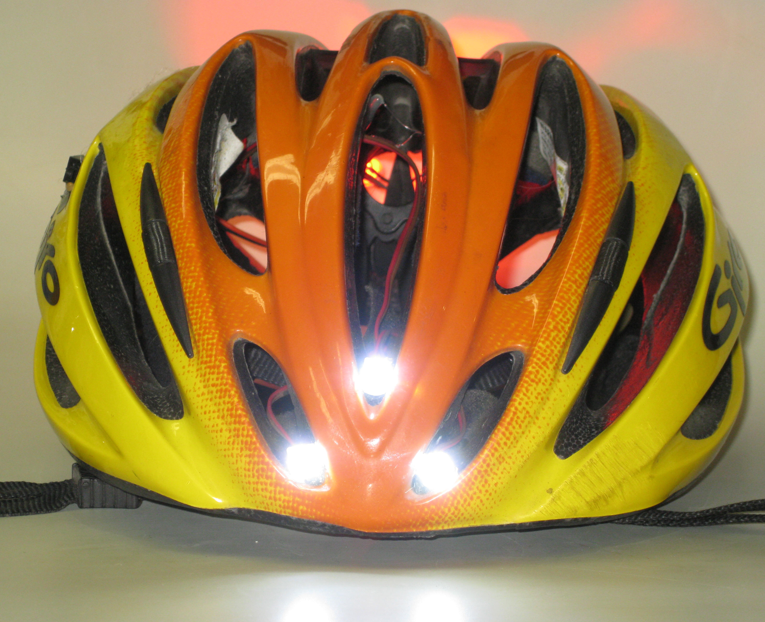
In order to give motorists the best chance of seeing my lights I like to have at least some illumination on my helmet. This is usually the highest point on a cyclist and the most likely to be noticed. The first version of this lighting system was made by mounting three bright white LEDs on the front of my helmet and three bright red LEDs on the back. A simple flashing circuit used a PIC 12F683 microcontroller. A single push button switch allowed for the selection of a number of different flashing modes and sequences. While this worked well it did little more than what was available with many commercial units.
Something More than Just Illumination!
I live in Pittsburgh and do a good bit of my bike riding in the winter. As
you can imagine temperature is always of interest and a topic of conversation
before, during and after each ride. I normally carry some sort of digital
thermometer on my bike rides and I frequently hear another member of the Mt.
Lebanon Cycling and Caffeine Club yell out "Dave, what
is the temperature now? It must be well below freezing!" I don't
mind being the resident temperature reporter in the peloton but it occurred to me that the flashing
lights on my helmet could be used to relieve me of this duty. By
incorporating a thermal sensor into the circuit and coming up with a way to
report its output with the helmet lights I would have an automated system that would take care of
continuously reporting the temperature.
Thus was born the "Bike Blinker +Plus+".
Objectives
My years as a classroom teacher proved to me the value of setting objectives
before starting a lesson or any other project.
The objectives for the bike blinker include that the unit will:
accurately measure and report temperature
report the temperature in a way that is easy to understand
be configurable to report the temperature in Fahrenheit or Celsius
have an option to report the minimum and maximum temperature observed
drive several bright red and white LEDs
operate from a 3.7 volt lithium ion battery or any other power source that can supply 3 to 5 volts
run continuously for at least two hours
have a push button switch to set options and to select the flashing mode
accommodate at least 4 operating modes
be small enough to be mounted on or inside of the vents of a helmet or in a small enclosure
be light enough to be unnoticed by the user
LEDs
The three white LEDs that I placed on the front of the helmet are 1/2 watt
devices that are unusually bright. (see Photo #2)
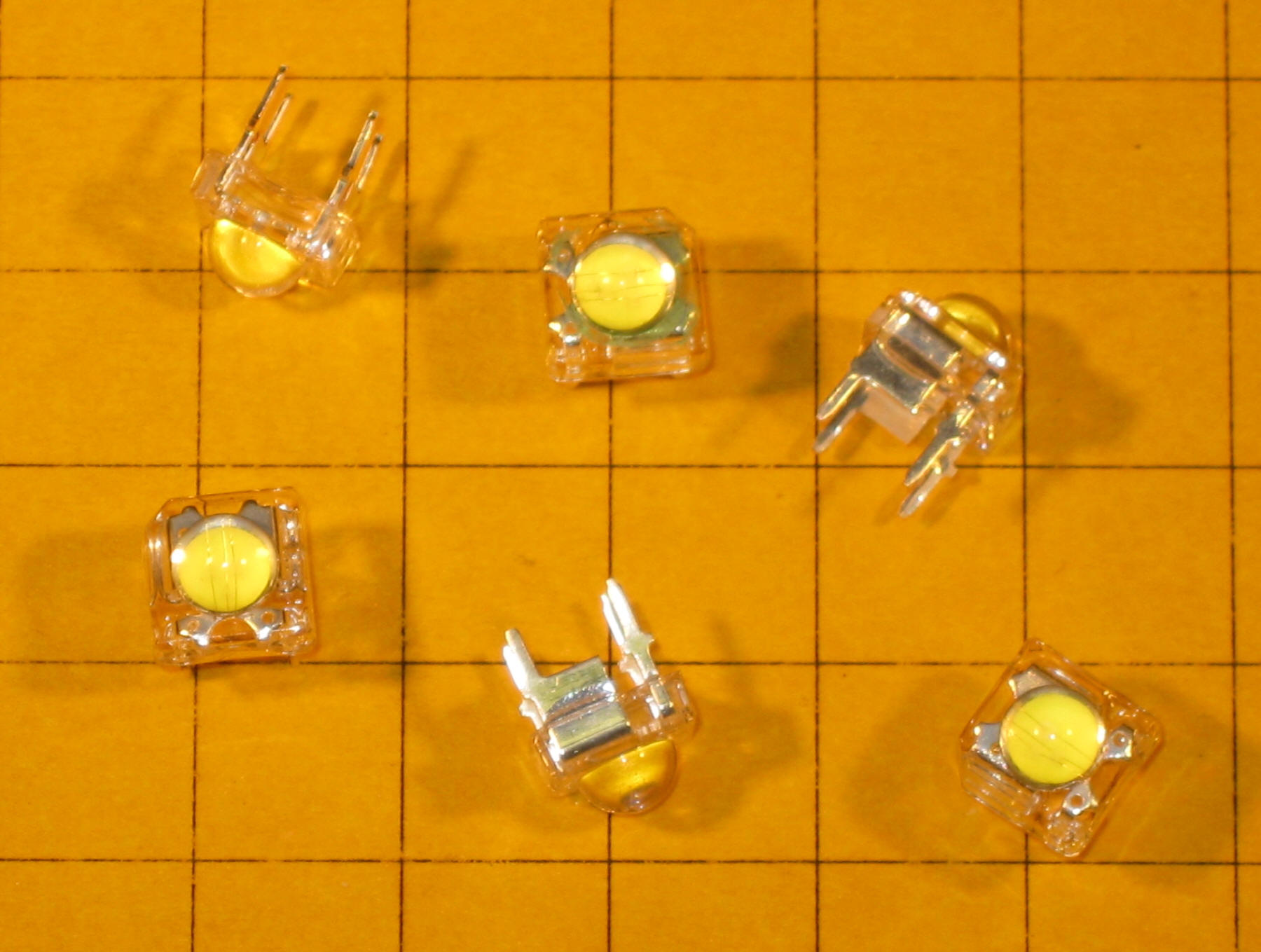
Photo #2
Each 5 mm LED enclosure contains three discrete LEDs. Photo #3 was taken through a red filter and shows one of the LEDs operating at a very low voltage. Because the intensity of the LED's light has been dramatically diminished you can clearly see the three points of light from each of the LEDs and the wires that are connected to them.
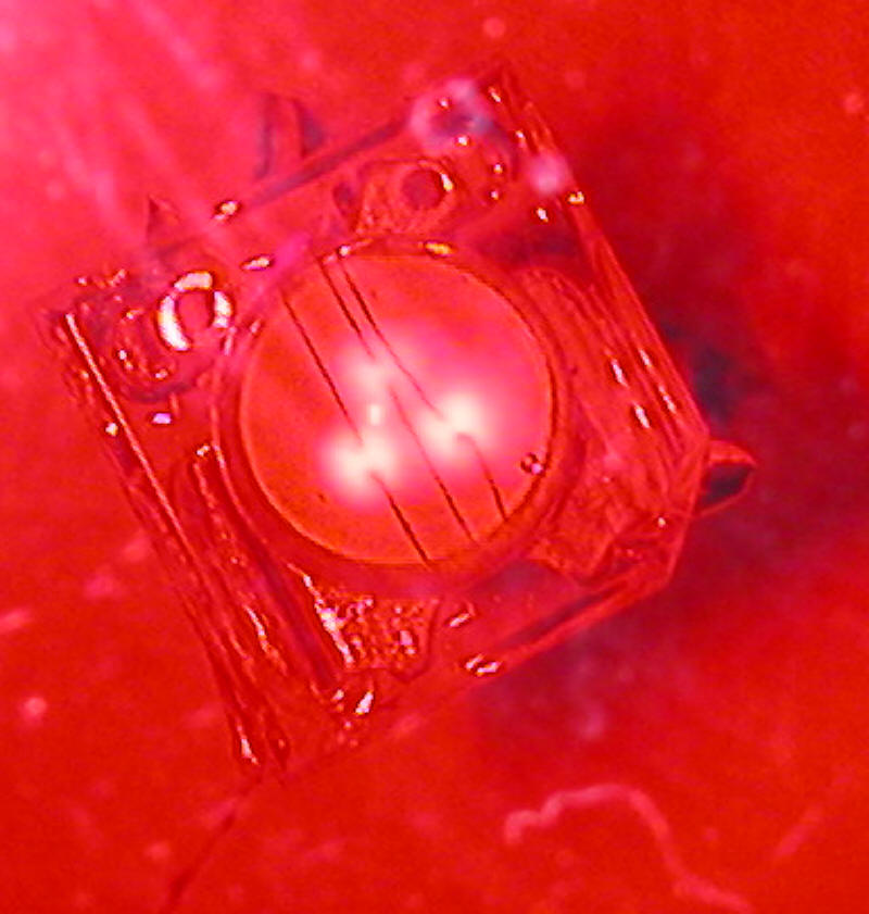
Photo #3
These LEDs provide a very bright light and each one only draws about 60 ma. They can be clearly seen in photo #1 which shows the front of the helmet.
The red LEDs for the rear are also rated at 1/2 watt. They are 10 mm units that throw a bright directed beam. One red LED faces straight back with the other two being aimed a bit to the sides. This arrangement gives maximum visibility. The vent to the right in photo #4 houses the circuit board and the sensor.
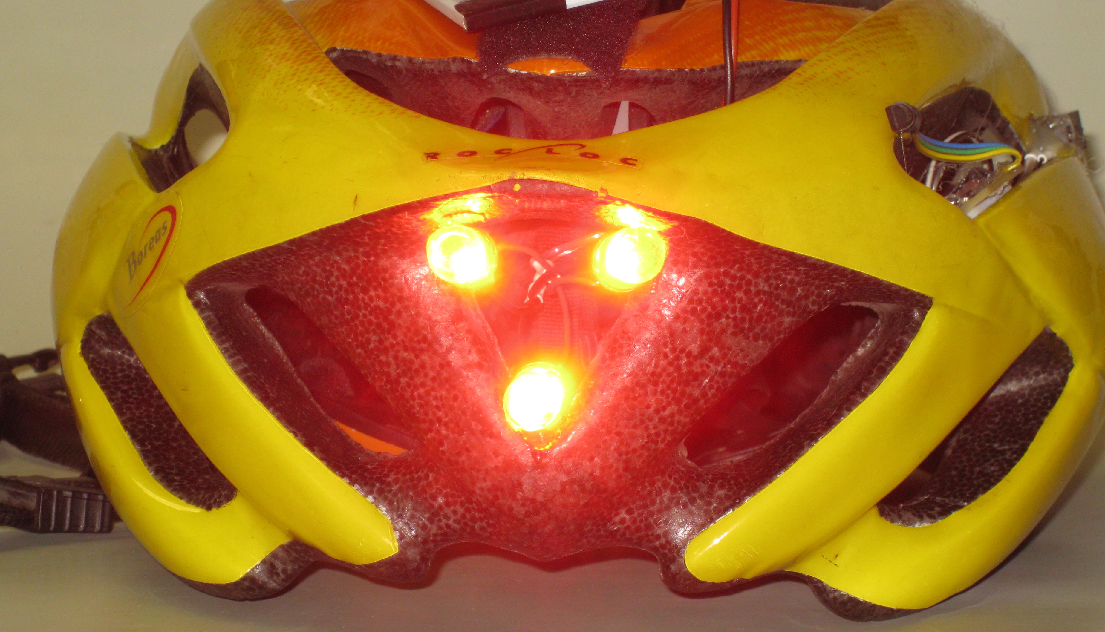
Photo #4
Temperature Sensor
Temperature readings come from a Dallas Semiconductor DS18B20. This
device uses a 1-wire protocol to communicate with the microcontroller and is
factory calibrated to an accuracy of +/- 0.5 degrees C. Routines to read
these sensors are readily available on the Internet and I had no difficulty
interfacing it to the PIC controller.
Getting Power to the LEDs
The LEDs that I am using draw much more current than the microcontroller
can supply from its output pins. A transistor is inserted between the
microcontroller's output pins and the LEDs to provide the necessary current. Any general purpose NPN
transistor should work. My first design used two 2N2222
transistors. I could have gotten away with using only one transistor but
decided that it would be simpler to use one transistor to drive the three front
LEDs and another to drive the three rear LEDs. This effectively doubled
the current handling capacity and saved me from experimenting with series
resistors that were needed to match the different
LEDs so that they could be operated by a single transistor. This
arrangement worked quite well and was used for several months. I continued
to experiment with the circuit and discovered that I could improve battery life
and LED brightness by replacing the 2N2222s with n-channel Mosfets. The
2N2222 transistors have a fairly high internal resistance and dropped the
voltage to the LEDs by well over 0.5 volts. Mosfets, on the other hand,
have a very low internal resistance and there was very little voltage drop
through them. I was also pleased to find that the Mosfets worked well when
substituted for the 2N2222s without any changes to the circuitry (See Figure #1)
.
Figure #1
Microcontroller
A PIC 12F683 microcontroller ties the hardware together by reading
the temperature sensor and a single pushbutton switch while operating the
flashing LEDs. I have used this chip for a number of model railroading
projects and knew that it had more than enough capability for this endeavor. I also
knew that the 8 pin 12F683 was available in a surface mount package that would
go a long way towards meeting one of the objectives, making the unit as small
and light in weight as
possible.
Construction
Solder the 12F683 microcontroller to the circuit board being sure to align
pin 1 properly. To check the wiring I like to program the chip as soon as
it is mounted. Just connect power (3 to 5 volts DC) to the board and plug in a four pin
header to the I.C.S.P. (in circuit serial programming) connection.
Successful programming will confirm that the chip has been installed correctly.
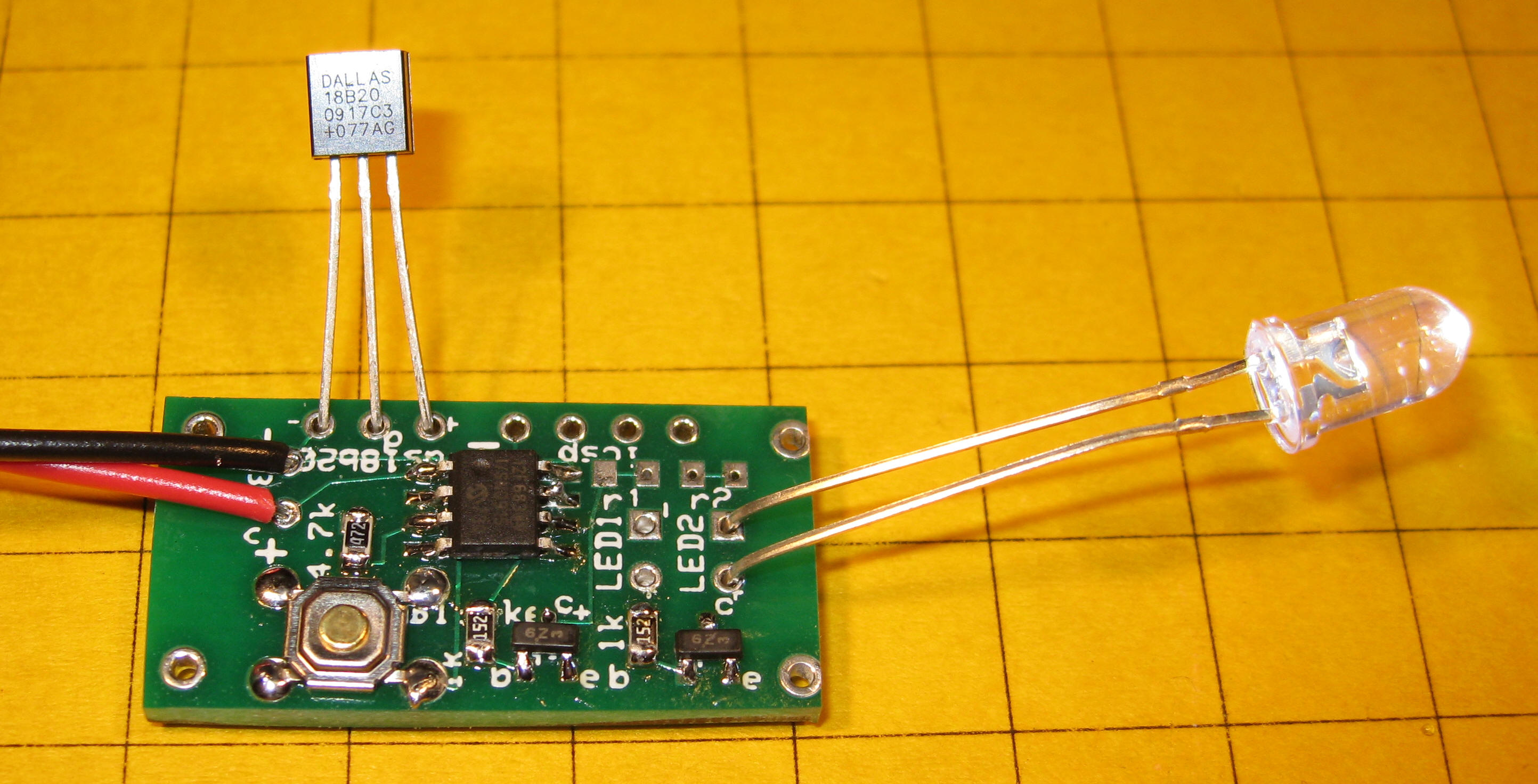
Photo #5
Next add the 4.7 K resistor and DS18B20 temperature sensor. Note the pin position of the sensor. The flat side of the device goes towards the center of the board. (See Photo #5)
Attach the resistors (1 K or 1.5 K) and Mosfets to the board. There is a spot on the board where a resistor can be added for each LED. This set of pads is jumpered by a small trace (circled in Photo #6) in the event that you don't need a current limiting resistor. If one is to be used you must cut that connecting trace before adding the resistor. I have run the unit using the LEDs shown here without current limiting resistors and have had good results. If you increase the input voltage to 5 volts you would surely need to add 50 or 100 ohms in series with the LEDs to keep from damaging them.
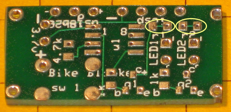
Photo #6
The push button switch needs to be oriented with its longer axis in line with the longer axis of the board. If you choose to use an external switch its wires connect to the upper left pad (the one with the hole in it) and the one in the lower right (next to the "1" in "sw 1").
Connect your LEDs to the board and apply power. The current Fahrenheit temperature should begin to flash out.
Using the Serial Output for Testing
Pin 7 and ground can be connected to a PC's serial port for testing.
The PIC's Pin 7 goes to pin 2 on the PC's DB9 serial port connector and ground
goes to pin 5 on the DB9. On your PC set HyperTerminal for 9600 baud, 8
bits, 1 stop bit and no parity. When power is applied to the completed Bike
Blinker the version number and current Celsius and Fahrenheit temperatures
should be displayed. (See Figure #2)
The comments in the PicBasic Pro program listing explain why the "Min/Max" temperatures shown on the HyperTerminal screen are 100 more than their actual values. They are stored on the PIC this way to accommodate negative temperatures on a device that does not normally understand negatives.
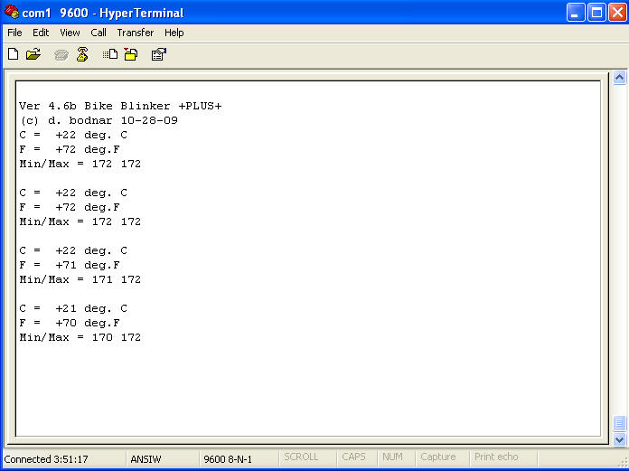
Figure #2
Software
The program for the 12F683 is written in PicBasic Pro. The code is well
documented and should be fairly easy to follow. You will also note that
there area a number of "SEROUT" commands. These send information
to the device's serial port and were used for debugging
as they give information on the program's operation.
If more program space is needed for additional modes or features the serial commands can
easily be removed.
Software |
Reading the Temperature
The objectives state that the temperature must be reported in a manner that
is easily understood. Being an amateur radio operator my first inclination
was to use Morse Code for the numbers but the thought of teaching the sequence
of dots and dashes to my riding comrades convinced me to search for another
alternative. The simplest code I could come up with has proven to be
easily understood by everyone who sees it.
A temperature report always starts with a rapidly blinking sequence where the LEDs flicker for 1/2 second or so. Next the number of hundreds of degrees is flashed out followed by a short pause, the number of tens, another pause and the number of ones. The software suppresses the reporting of hundreds of degrees if the temperature is below 100. When reporting numbers of degrees the LEDs flash at a rate of about 1/3 second on and 1/3 second off . When reporting a zero they flash on and off much more rapidly. These rates can easily be changed in the software but have worked well throughout a full year of testing.
|
To report 103 degrees
|
To report 48 degrees
|
To report 7 degrees
|
|
To report 0 degrees
|
To report 7 degrees below zero
|
The Minimum / Maximum temperature reports (mode 5) work as follows:
|
The temperature reports are the same whether they are reporting Fahrenheit or Celsius temperatures. You must remember which scale you have the unit set to report.
One Button Does It All!
A single SPST momentary switch takes care of all mode and configuration
changes. The unit currently has five different operation modes:
Continuously display temperature in Fahrenheit or Celsius
Blink rapidly (approximately 8 times per second)
Blink slowly (approximately 1 time per second)
LEDs on (no blinking) - great for fixing flats in the dark, not so good for battery life
Display the current temperature then the minimum temperature that has been seen since the unit was turned on then the maximum temperature that has been seen since it was turned on. The current temperature is shown in the normal manner. The minimum temperature report is preceded by the LEDs slowly going from full brightness to dim and the maximum temperature report is preceded by the LEDs slowly going from dim to full brightness.
When the button is pressed the LEDs flash out the number of the new mode. If the button is held the mode number is flashed out repeatedly. Releasing the button initiates operation using the newly selected mode.
There are several other functions that the button controls:
If the button is held for a few seconds as the unit is turned on the temperature reports change from Fahrenheit to Celsius or from Celsius to Fahrenheit. The current mode is reported by flashing out either a Morse Code "C" [long flash, short flash, long flash, short flash] or a Morse Code "F" [short, short, long, short]
If held long enough for the mode selection to flash out five times the LEDs will slowly dim and go out and the unit will turn off.
Pressing the button while the unit is off will turn the unit back on, indicated by the LEDs slowly going from off to full brightness
The blinker doesn't fully turn off when the button is held down as described above. It enters a very low power sleep mode. An on/off switch can be added to the circuit to completely turn the power off. This may be desirable as the batteries will slowly be exhausted if the unit is left in sleep mode for weeks or months.
If you do not install an on/off switch you can still change the Celsius / Fahrenheit scale by putting the unit to sleep then holding the button down when you turn it back on. The current temperature scale will be displayed after the unit awakes. Continue holding the button and it will change to the other scale.
The mode is saved when the unit goes to sleep or is turned off so that it returns to the last selected mode when it restarts.
A video is available on the Nuts & Volts web site that shows the operation of the unit in its various modes.
Battery Choices
I operate my helmet lights with 3.7 volt rechargeable lithium
ion batteries that were designed for cell phone or PDA use. The circuit will
also work well with any power source that supplies
from 3 to 5 volts. Three rechargeable NiHM AA or AAA cells in series work
well. If you opt to use a voltage greater than 3.7 volts you may need
to add current limiting resistors in series with the LEDs. Their value
will vary depending on the LEDs you choose and the voltage of the batteries.
Mounting Options
As you can see from the photos I mounted the LEDs and blinker circuit inside
of the vents of my helmet. The three white LEDs were mounted inside of
front vents with hot melt glue and the red LEDs were similarly glued inside of rear facing vents.
The circuit board was mounted with double sided foam tape inside of a top vent
and the battery was mounted with Velcro to the top rear of the helmet.
This arrangement works very well and gives the system a nice integrated look.
I put the DS18B20 on the end of short piece of three conductor ribbon cable so that it is a few inches from my scalp. Even then the temperature tends to go up when I stop at a traffic light on cold days as it senses my body temperature.
The mode button is also mounted externally by wiring a second SPST momentary switch at the end of the vent. This makes it much easier to change modes while riding.
For those of you who would like a less permanent installation or who would like to have the option of moving the light from helmet to helmet you can easily mount the circuit board, battery and LEDs in a small box as shown in photo #7. The DS18B20 is in the lid just left of center and the yellow and orange wires go to an externally mounted mode button. You will also note that the positive lead from the circuit board goes directly to the metal case as do the anodes from the six LEDs. This simplifies wiring as the only leads that come back from the LEDs to the circuit board are those from the cathodes. The SPDT toggle switch turns the unit on and off. When the switch is off the rechargeable battery connects to a charging plug (hidden from view in this photo) so that you cannot inadvertently apply charging voltage to the circuit.
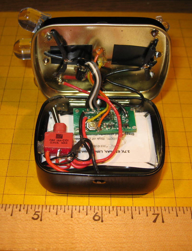
Photo # 7
Enhancements
The next revision of the circuit board will control each of the two Mosfets
with a separate pin on the PIC processor. This will allow independent
control of the front and back LEDs. This would allow a mode, for example,
that would leave the back red LEDs flashing while the front white LEDs could be
on constantly so that you could read a map or perform repairs. I am sure
that additional modes of operation will come to mind as well.
I am also considering, at the request of a non-cycling friend, making a solar powered unit with only one LED. It will be placed in his garden to continuously report the outdoor temperature. He reasons that it will give a better outside reading that a thermometer close to the house and he will be able to read it without putting on his glasses!
Conclusion
I have made a number of Bike Blinker +Plus+ units for personal use and for
friends. I encourage you to do the same! I think that you will find
that it can add to your visibility and may provide some fun as well.
Try this: leave your helmet flashing on the bike when you go into the local coffee shop. Invariably someone will tell you that you forgot to turn the light off. Watching their reaction as you relate how it is giving you temperature reports is an added benefit that is sure to make you smile!
Parts List
White LEDs - eBay seller Ivehk - 5mm 0.5W MultiChip White Flux LED 50Kmcd
Red LEDs - eBay seller Ivehk - 10mm HIGH POWER 0.5W RED LED LAMP 150,000mcd
Microprocessor - 12F683 - Digikey.com - Part # PIC12F683-I/SN-ND
Temperature Sensor -DS18B20 - SparkFun.com - Part # SEN-00245
N-Channel Mosfet - Digikey.com - Part # eMMBF170LT1GOSCT-ND
Switch - SPST momentary - Electronic Goldmine - Part # G13795
Resistor R1 & R2 - 1K or 1.5K SMT - Electronic Goldmine - Part # G255R
Resistor R3 - 4.7K SMT - Electronic Goldmine - Part # G266R
Resistors - none or to match your LEDs - see text - Electronic Goldmine - SMT 1206
Circuit board & complete kit of parts available from the author (dave@davebodnar.com)