I recently came across a number of vendors on eBay and elsewhere selling small circuit boards that billed themselves as "Wireless RS232 Bluetooth Transceiver Modules". These really caught my interest for a number of reasons. First was their low cost, many could be had for well under $20.00 with the one from Deal Extreme coming in around $6.00. My primary interest was to connect one of these devices to a microcontroller based device in one of my railroad controllers so that I could gather telemetry data from a moving train. It also has the potential to be used to control a train via Bluetooth. I ordered units from a few vendors and began experimenting when they arrived.
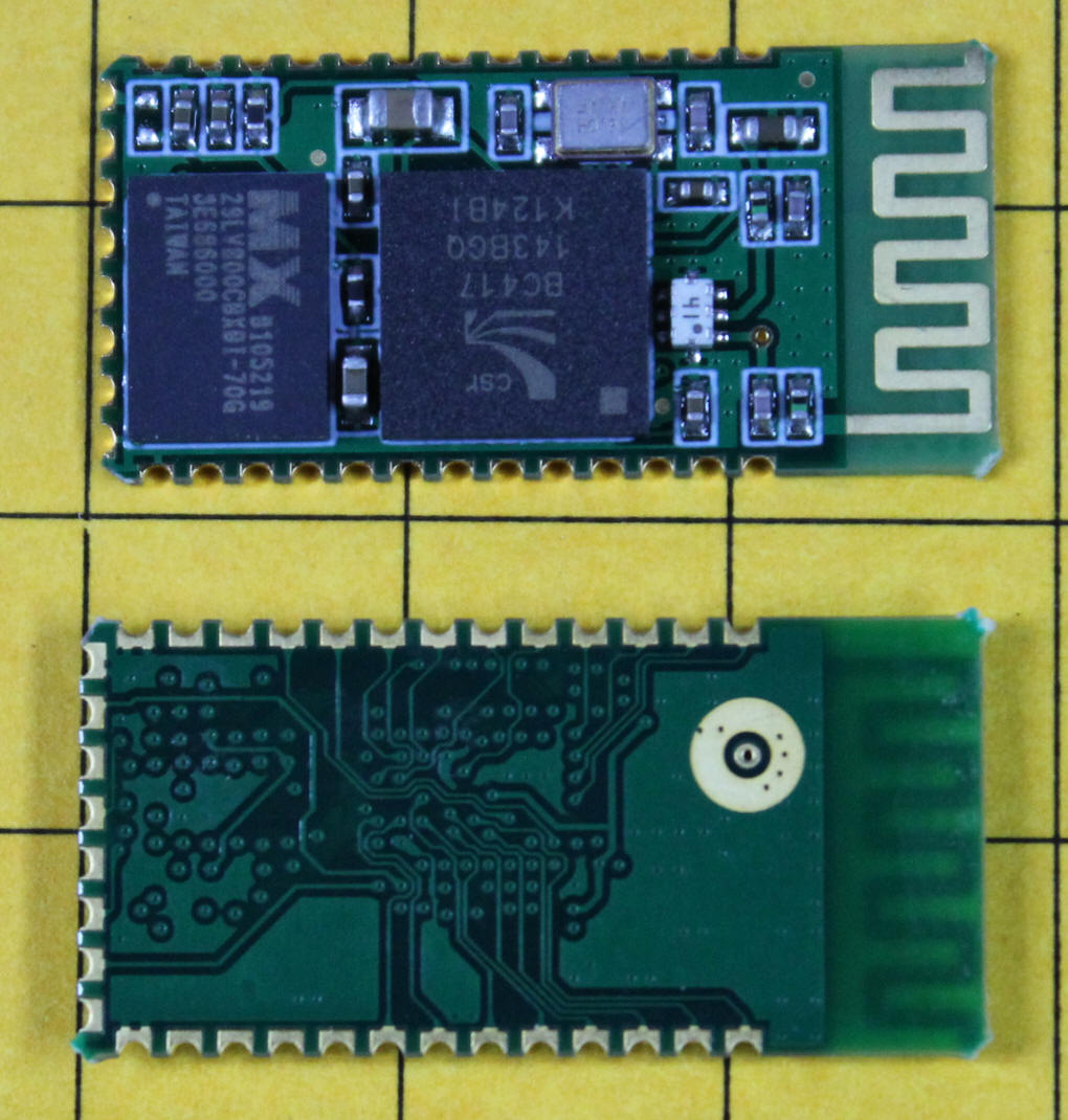
All of the units that I ordered are very similar and are based on the same chip set. The unit shown here is from Deal Extreme, part # 80711. The antenna is at the right and the connections to the board are on the top, left and bottom edges. They are referenced by calling the top right indentation "1" and counting sequentially in a counter clockwise direction around the board with the last connection numbered "34". There are 13 connections on the top, 8 on the left side and 13 on the bottom. The plated contacts can be seen more clearly in the photo of the back of the board.
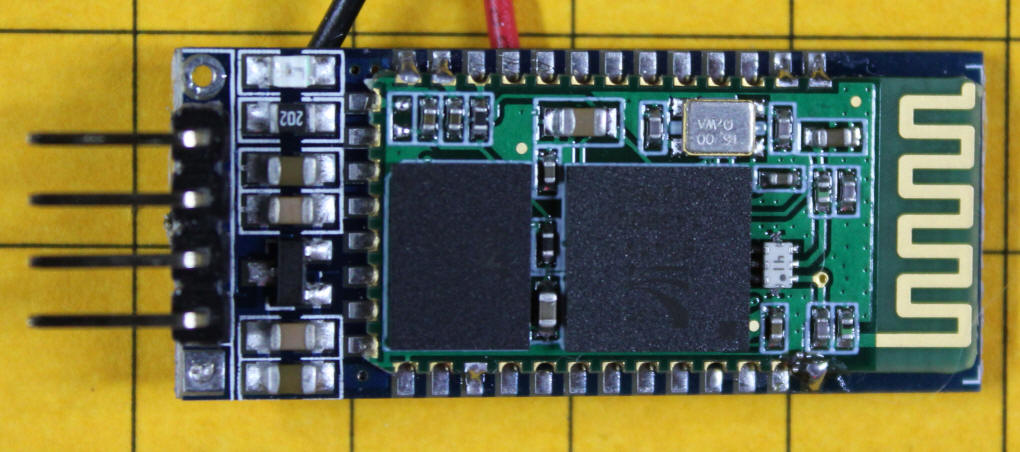
Some of the boards are more convenent to work with as the main circuit board is attached to a secondary board. Here is an example that was purchased on eBay. The four pins coming out of the left side are for RX data, TX data, Ground and VCC (3.3 volts). There is a small red surface mount LED in the upper left corner. It flashes or stays on steadily depending on its connection status. The red and black wires at the top are wires that I added and are soldered to the power pins.
The modules required 3.3 volts DC with the exception of one that could run with either 3.3 or 5 volts due to the inclusion of a voltage regulator on the secondary circuit board. Bringing the boards to "life" was as simple as applying voltage to the appropriate pins. The units with an on-board indicator LED began to flash indicating that they were ready to be found by another Bluetooth device. Since the Deal Extreme boards were bare an LED and 470 ohm current limiting resistor were added to pins 22 (ground) and 24, referred to as PIO(1).
Once power was applied I used a Bluetooth equipped Android tablet (and later my Android phone) to attach to the boards. Their default names were all "linvor" and each was found without any trouble. On the Android devices I used a terminal program called Blue Term to attach to them. Unfortunately there is nothing that you can do beyond attaching unless something is attached to the serial port on the module.
To experiment with the serial port I connected the ground, transmit and receive pins to pins 5, 2 and 3 on a DB 9 and hooked up to my PC through a serial to USB adapter. After a number of unsuccessful tests and experiments with baud rates and settings I discovered that the voltages on the modules was not appropriate to talk to a computer without some modification. I found a number of entries on the Internet that indicated that the best way to accomplish this modification was to use a MAX232.
The circuit that I used is shown below. The capacitors are tantalum 4.7 uf devices. The documentation for the MAX 232 calls for 1 uf but all I had on hand were the 4.7s and they work fine. I used a 5 volt regulator (78L05) to supply the MAX232. To get the lower voltage for the module I put three silicon diodes in series dropping the 5 volts to 2.9 volts.
The circuit performs very well and allows direct connection between the Bluetooth module and either my Android device or the computer. It also works with both PIC and PICAXE microcontrollers. The program that I use on the computer is called Tera Term. Since Windows 7 does not include HyperTerminal it is a good substitute and the price is right (freeware!).
This photo shows the circuit built for testing on a prototype board. The Bluetooth module is at the left. The jumper is in the far left. The 3 pin header connects to the DB-9.
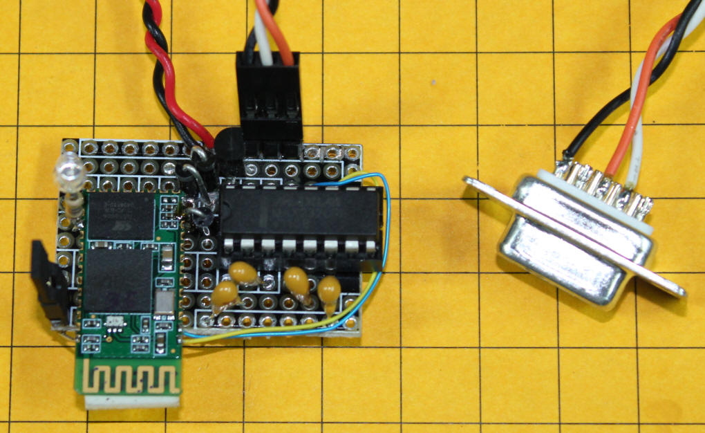
In order to put the module into command mode, which is used to change the baud rate and name, you need to connect pin 34 to the positive voltage terminal. The schematic shows a jumper that can be used to connect these contacts.
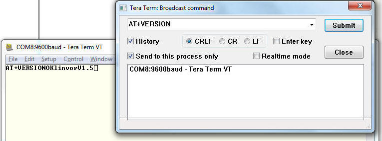
When I first go the module working with Tera Term I typed AT on the terminal and the module responded OK. I tried other commands that were in various documents that I found and never received a reply from the device. A bit of experimentation determined that just typing the commands did not serve to communicate with the module. I needed to use a different method. Using Tera Term I selected CONTROL from the pull down menu then BROADCAST COMMAND.
With the settings shown below I was able to communicate with the Bluetooth module. As you can see the command "AT+VERSION) returns "linvolV1.5".
Other commands that work with these modules include:
AT+NAMEnewnamehere can be used to change the name of the module. Using AT+NAMEDE-three changes the name to "DE-three"
AT+PINxxxx sets the password (PIN number) - I have not tested this as I left all of my modules set to the default 1234
AT+BAUD# where # is a digit between 1 and 9
1 >> 1200
2 >> 2400
3 >> 4800
4 >> 9600 (Default)
5 >> 19200
6 >> 38400
7 >> 57600
8 >> 115200
9 >> 230400
AT+PN sets parity - not tested