|
|
|
Crossing Badge
revised 6-27-2018
SHMRRC Badges
|
|
|
| Introduction A few years ago I built a simple railroad crossing name tag to wear at local train shows where the two clubs that I belong to set up displays. It was based on a circuit that I used on my bicycle helmet to flash lights as I rode in the dark. Recently I decided to update this project by designing a custom circuit board that would better fit behind the laser cut crossing badge.
On this web page I will document the process followed to create the new badge.
|
||
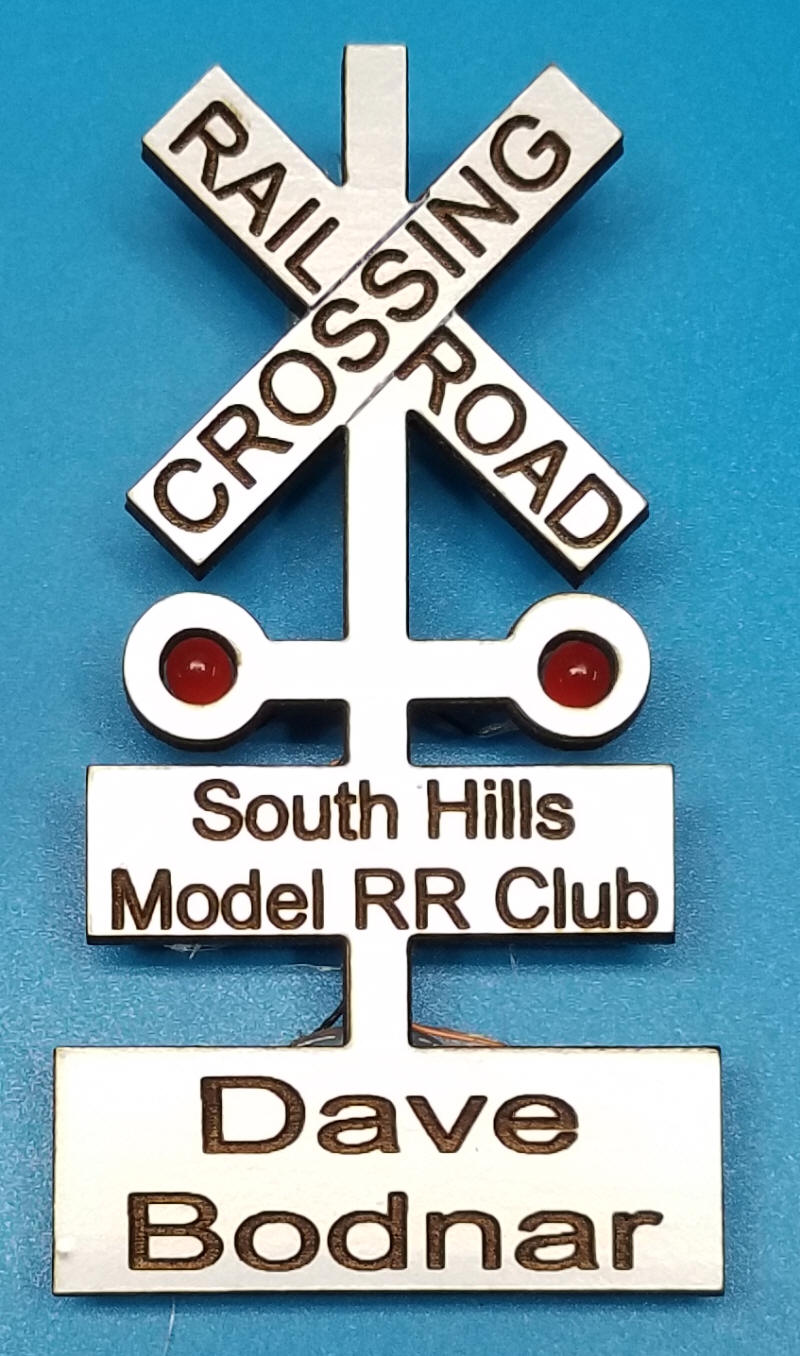
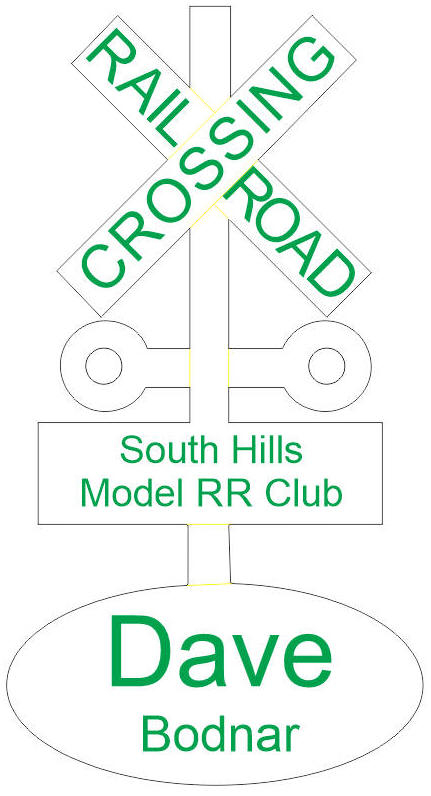
| The Badge Design The first step was to redesign the original badge that was created in CorelDraw. These changes were minor and included making the name portion an oval rather than a rectangle and fine tuning some of the lettering.
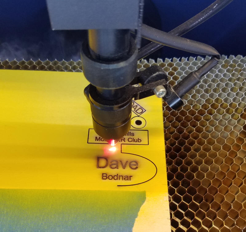
The CorelDraw file was sent to my laser cutter for engraving and cutting. I experimented with a number of different materials. 1/8" plywood, dyed yellow, is shown here. Other materials include clear and painted acrylic and hard woods (such as maple or walnut).
The CorelDraw file (in .cdr
format) is here: These files should import into most graphic programs for editing. |
||
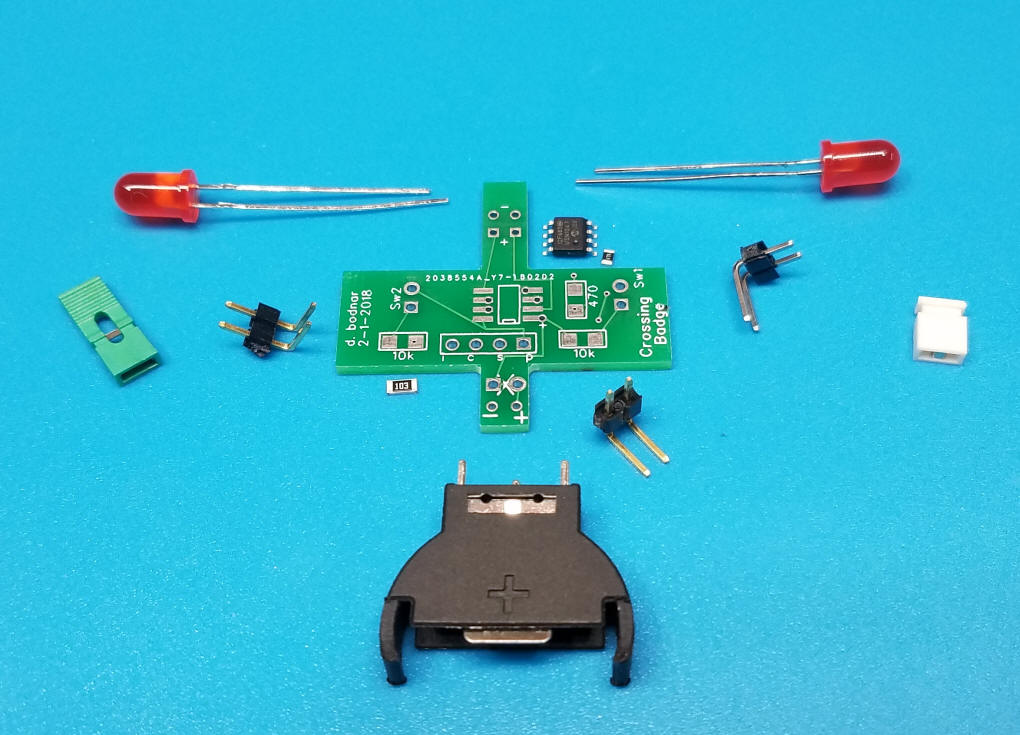
| The Circuit Board I designed a simple circuit board using a no-longer-supported program called FreePCB. The design file is here: CrossingBadge/Crossing-badge--02-01-18-asSubmitted.fpc and the Gerber files are here: CrossingBadge/gerber/CrossingBadge.zip The PIC processor, an 8 pin 12F683, goes near the center. The two LEDs connect to the pads at the top. The two jumpers, which are used to select blinking modes, go to the left and right near the Sw1 and Sw2 labels. The 470 ohm resistor limits current to the LEDs and the 10k resistor on the left is used to pull pin 4 high,. The 10k resistor on the right can be skipped. Programming is done via the 4 pins labeled ICSP (In Circuit Serial Programming). Power, from a 3 volt 2032 cell, goes to the two pins at the very bottom, If you want to add a jumper that needs to be installed to turn the power on cut the trace at the bottom (marked with an X) and install the on/off jumper there. I tested the circuit with two 5mm red LEDs set to flash back & forth every 1/2 second and, with a new 2032 cell, it ran for 5 full days. Not bad!
|
||
|
|
||
|
Parts
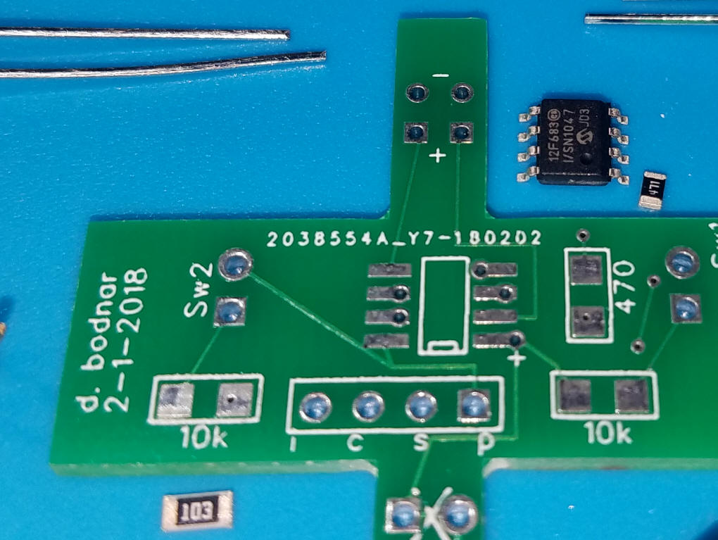
This close-up shows the surface mount resistors and the surface mount version of the 12F683. The 470 ohm resistor is marked 471 (47 times 10 to the first power) and the 10,000 ohm resistor is marked 103 (10 times 10 to the third power)
|
||
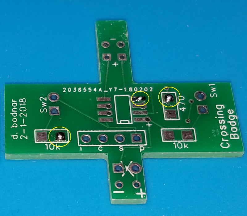
| Soldering the Board I like to solder surface mount components before through-hole items. For each component I first place a small amount of solder on one of the pads for each component as shown here. The pads where solder was added are circled in yellow.
Next place the appropriate pin of the 12F683 so that one pin (#4 in this case) sits right on the solder that was added. Heat the pad and press the chip down squarely. Take note of the small dimple on the 12F683 that marks pin #1.
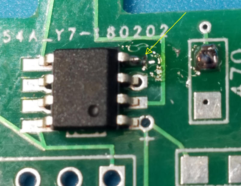
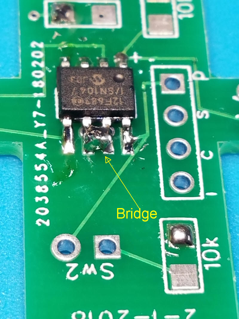
Once the chip is centered on the other pins simply solder each of the other pads. It is not unusual for two or more adjoining pins to be short circuited by a solder "bridge" as shown here.
If that happens you can use solder wick or a solder sucker to remove the bridge of you can try the trick that I generally use. Hold the board perpendicular to the table, heat the solder bridge with the iron and, when the solder bridge is well heated, bang the edge of the board on the table. The excess solder usually flies off clearing the bridge. (BE SURE TO BE WEARING SAFETY GLASSES WHEN DOING THIS AS SMALL BITS OF SOLDER FLY ABOUT! ! !)
After smacking the board on the table the bridge is gone and some small bits of solder are on the table. Be sure that none of the solder is sticking to other components before proceeding.
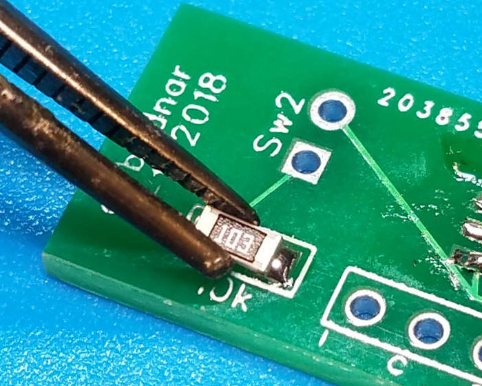
I use tweezers to hold the surface mount resistors. Place one end of the resistor on the solder pad and apply heat to melt the solder. Once that is done the tweezers can be removed and the other end soldered.
|
||
| Construction After the surface mount components have been added solder the two LEDs. First place an LED into one of the holes in the badge with the negative lead (the shorter wire identifies the cathode) to the top and the longer wire (the anode) to the bottom by the + sign.
Repeat with the other LED.
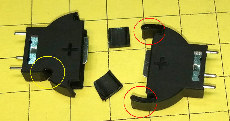
The battery holder that I used can be modified to make removal of the 2032 easier. The original holder is on the right and the modified one is on the left. Trim the arms that extend from the bottom of the holder as much as possible. With the arms in place the cell is very hard to remove. With the modification the cell still stays put but is much easier to remove. I also like to put a notch in the holder so that a small screwdriver or similar object can be inserted into the hole to force the cell out. The notch location is circled in yellow.
|
||
|
Software The program was written in PICBasic Pro. If you have that program copy & paste the code into your editor and compile & program the chip. If you do not have PICBasic Pro you can use the HEX file here: CrossingBadge/ditch_Crossing12683_v7Mars.hex to program the chip directly. |
||
ansel = 0   '' needed to get pin 3 (gpio.4) as input  ''  http://www.microchip.com/forums/m190353.aspx
DEFINE DEBUG_REG PORTA
DEFINE DEBUG_BIT 0         ' PIN 13 on 16f684
DEFINE DEBUG_BAUD 9600
DEFINE DEBUG_MODE 0 ' Set Debug mode: 0 = true, 1 = inverted
option_reg.7=0          'turn on weak pull ups
wpu = %00010000         'weak pull ups on pin GPIO.4 only
Jumper1 var gpio.3 'switch to choose ditch or crossing  - pin 4 - needs pull up
Jumper2 var gpio.4 ' pin 3
gpio = %00011010
led1    var byte
led0    var byte
temp    var byte
lo      var byte
hi      var byte
stp     var byte
pwmcycles var byte
pwmcycles=1
stp=2
lo=10'160
hi=255
debug 13,10,13,10,"Ditch / Crossing / Mars Light Test",10,13,"(C) 2-12-2018 - d. bodnar - ver 7",13,10,"TrainElectronics.com",13,10
Xx              var byte
PTime           con 500
Pin5Out          con 1

top:
if Jumper1 = 1 and Jumper2 = 1 then     ' both off
  CCP1CON = %0000 'PWM mode OFF
  goto Crossing
endif
if Jumper1 =0 and jumper2=1 then
  CCP1CON = %0000 'PWM mode OFF
  goto ditch
endif
if Jumper2 = 0 and jumper1 = 1 then Mars

BothOn: 'both jumpers on
high 2:high 13:high 1
goto top

Crossing:
low 2 :high 13 :pause 500
low 13 :high 2 :pause 500
goto Top

Mars:
low 2:low 13
'up high
for xx=1 to 255
  hpwm Pin5Out, xx, 20000
  pauseus PTime
next xx
'down full
for xx=255 to 1 step -1
  hpwm Pin5Out, xx, 2000
  pauseus ptime
next xx
'up medium
for xx=1 to 155
  hpwm Pin5Out, xx, 20000
  pauseus ptime
next xx
'down full
for xx=175 to 1 step -1
  hpwm Pin5Out, xx, 2000
  pauseus ptime
next xx
goto top

Ditch:'led0=13
led1=13:led0=2:gosub doit1:
led1=2:led0=13:gosub doit1:
goto top

doit1:
  for temp=lo to hi step stp
    pwm led1, hi-temp+lo, pwmcycles
    pwm led0, temp, pwmcycles
  next temp
return
|
||
|
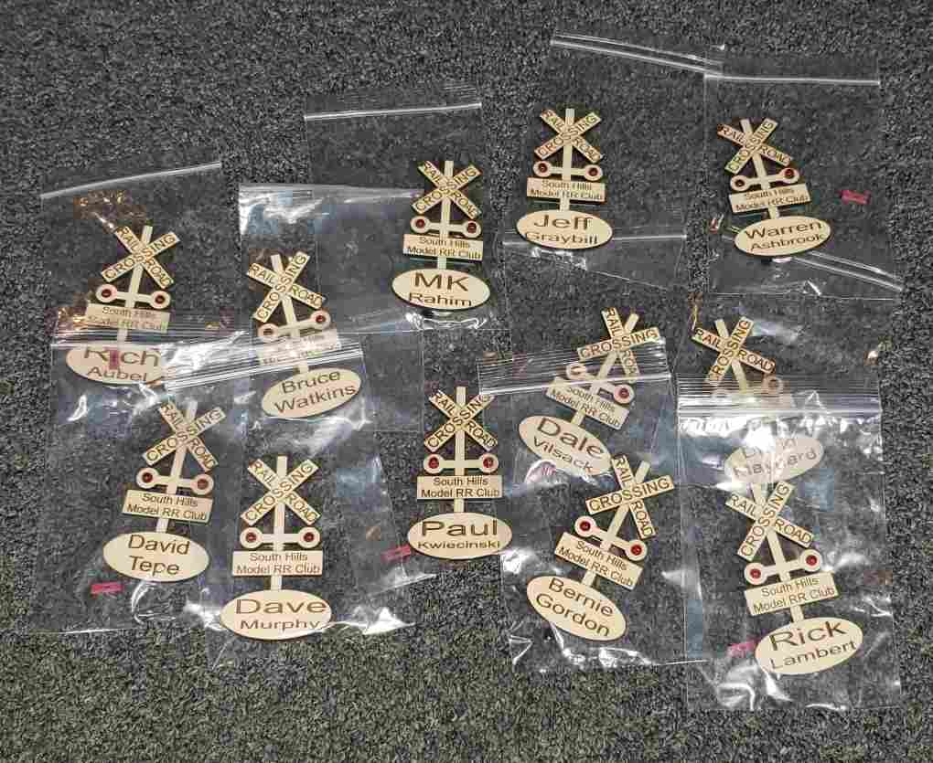
The badges for the SHMRRC are shown below. Each bag contains a badge with a new 2032 battery and two spare jumpers (they are easy to lose!).
The circuit is shown on the right and the laser cut badge on the left. There is a small notch on the left side of the black battery holder - that was added to facilitate removing the battery using a small screwdriver or similar tool. There are two magnets at the top of the badge. Slide one off and use it to attach the badge to a shirt.
The circuit board/battery are held to the plywood with Glue Dots - this semi-permanent adhesive allows the two to be separated to allow for reprogramming or repair.
The jumpers are shown in this photo with both of them not shorting two pins. When the red jumper is on both pins the badge flashes. When it is removed or placed on only one pin the badge is off. The black jumper is shown in the off position (only on one pin) - when the jumper is on both pins the LEDs brighten and dim rather than flash. Note that the jumpers are functionally identical and can be swapped from one position to the other.
Here the red power jumper is ON.
|
||
|
|


