| Overview: The microcontroller produces pulses at 38 kHz on pin #5 (out2) which drive two infrared LEDs through 220 ohm current limiting resistors. These IR LEDs are placed on either side of the crossing. The IR sensors (PNA4602M) are placed next to the IR emitters so that they will detect IR that reflects off of the passing train. (The article referenced above goes in to detail about the placement of the emitters and detectors) When a train passes in front of either sensor a pulse from the PNA4602M is detected and the relay that is connected to pin #6 (out1) is pulled activated. When the train passes in front of the other sensor the microcontroller begins to monitor the sensor and opens the relay after no additional pulses from it are received for several seconds. This assures that the entire train has passed the sensor before the crossing relay is opened and the crossing lights extinguished. This circuit does nothing to flash the lights or start sounds. It only activates whatever is connected to the relay contacts. It should be possible to use the Test LED output on pin #7 (out0) to flash lights should that be desired. As it is now the Test LED simply shows when the second sensor is pulsing as the train passes it. |
| Schematic PICAXE 08M Version: Notes:
|
| Software for 08M Version: Notes:
'08M Crossing Controller - d. bodnar
02-01-08
|
| Schematic 16F684 Version The two schematics are nearly identical except for the location and connection of pins. The jumper allows for switching between sensors that are looking for reflected light and those that are "across the tracks" units. With the jumper removed (open) reflective sensors are used.
If the power supply is noisy the following filter, composed of C3 and R8, is suggested to clean up the pulses from the detector. Duplicate the filter on each detector.
|
| Software for 12F683 version
(38kHz_IR_12f683-Crossing_Signal_Controlv1-4): Notes:
|
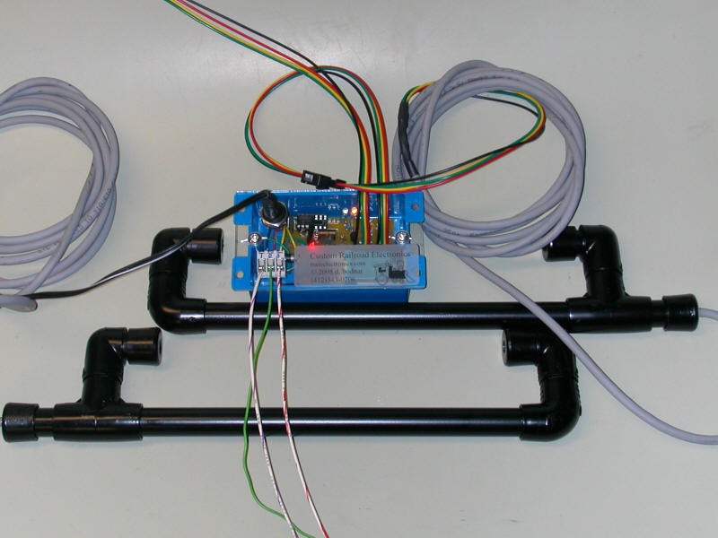
| Prototype Unit - 12F683 version The test unit is shown below. It used sensors that are constructed based on the information discussed under Projects / Infrared Train Detector It's ugly but it works!
Here is the 2nd version - much neater!
|


.JPG)
.JPG)
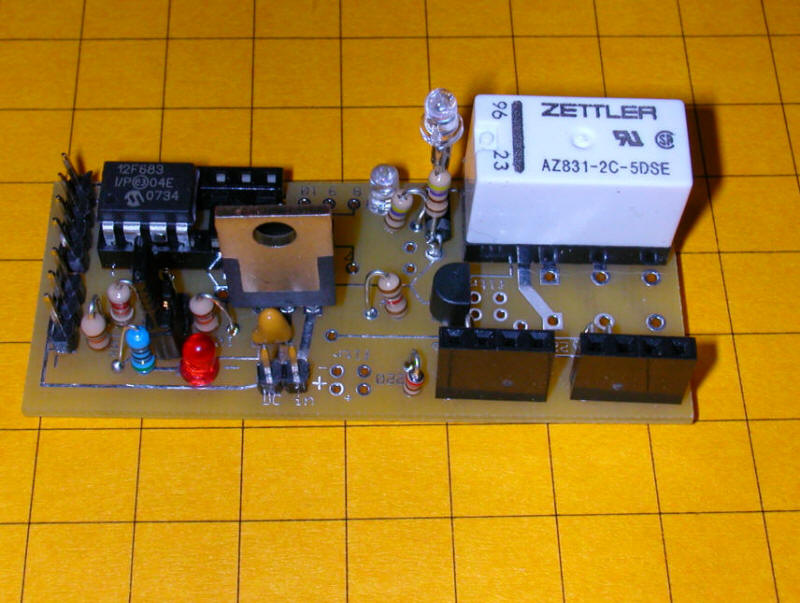
| Custom Circuit Board After successful testing of the prototype a custom board was designed and sent out for fabrication. The result is shown below. The microcontroller is in the upper left, a 12f683 PIC. The board will also support a PICAXE 08M or 14M as well as PIC 16F684. The relay is in the upper right. The two IR emitter / sensor units connect to the 4 pin headers in the lower right. DC power (6-24 volts) connects to the 2 pins bottom center.
The two sets of pins at the bottom of this photo are the programming connections. The set of 3 pins is for programming a PICAXE. The set of 4 pins is for PIC ICSP programming. The jumper (lower right) determines if the sensors are reflective or across-the-track units.
The LED next to the relay lights when the relay is closed. The other LED is for testing. The 7805 voltage regulator is clearly visible in this image.
Some additional wiring was needed to support the test LED
|
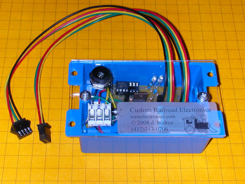
| Complete Crossing Unit The unit below is an enclosed version of the controller. The two 4 wire cables connect to the two IR sensors. Power goes into the receptacle in the upper left and the three track connections go to terminals 1, 2 and 3 in the lower left.
The following diagram assumes that the main line is the oval. The train can run in either a clockwise or counterclockwise direction. The trolley that is stopped to avoid a collision at the crossing is on the point-to-point labeled "Controlled Line".
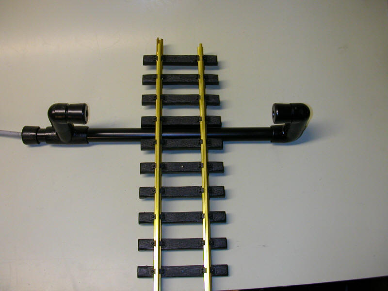
The trolley line is broken by insulators into several isolated blocks. The two "Diode Blocks" are needed to stop the train at either end. The block of concern to us are those labeled "Stop Block 1" and "Stop Block 2". One is to the left of the crossing and one to the right. The power to "Stop Block 1" goes to the terminal marked 1 on the controller. Terminal number 2 on the controller goes to the live part of the track. Note that there is a jumper from each end of the isolated track to the center section that goes through the crossing. These three sections must be connected with the connection continuing to terminal #2 on the controller. Note that all of the cuts in the track happen on one side of the track. The sensors go on either side of the crossing at a distance of 2 or 3 feet from the crossing. When the main line train hits one sensor or the other the amber LED in the controller box lights and the stop blocks go dead. When the other sensor is hit the green LED lights briefly and power is restored to the blocks.
You will notice that the trolley will only stop in Stop Block 1 or 2 if it is heading towards the crossing. If it is in the crossing or past it power will not be cut. This photo shows the complete unit. The sensors attach to the controller through seven foot cables. The track connections are the through the wires in the lower left.
|
.JPG)
.JPG)
.JPG)
.JPG)