|
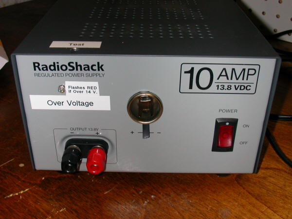
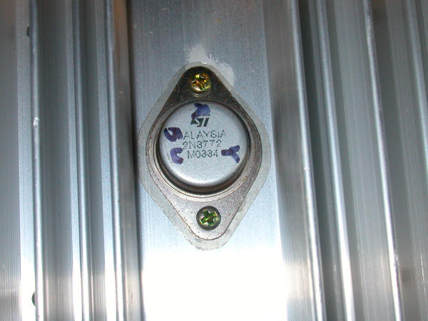
This circuit adds a crowbar to Radio Shack's 10 amp, 13.8 volt power supply (#22-506). The Radio Shack design provides no protection should the pass transistor, a 2N3772, short out, a fairly common occurrence. This failure will put the power supply's reservoir voltage, nearly 24 volts, on the output terminals - not a good thing for devices expecting 13.8 volts!
This shortcoming of the power supply was discovered when I was helping a friend get his railroad set up this spring. His Aristo Craft Train Engineer receiver was not working. A quick check of the voltage coming from the power supply showed that it was not 13.8, as advertised, but 24 volts. This was clearly beyond the limit of what the Train Engineer could take especially when you consider that a much higher voltage spike may have occurred at the moment of failure. When the receiver was opened a good bit of damage was found. Four of the power components, two Mosfets, one 7812 voltage regulator and one Schottky barrier rectifier were all fried and one trace on the circuit board was gone. I repaired the receiver but the power supply was a concern. A new 2N3772 was all that was needed to return the properly regulated 13.8 volts to the output terminals of the power supply. But before putting that unit back into service I decided to add an over-voltage protection circuit so that another failure of the 2N3772 or another component wouldn't damage something again. The Circuit The protection circuit is very straight forward. A DPDT relay with a 24 volt coil is connected so that the positive 13.8 voltage from the power supply has to go through its normally closed (NC) contacts. If the relay is activated and pulled in the contacts open and power is removed from the terminals. The detection circuit that activates the relay is just a potentiometer, acting as a voltage divider, and a 2N2222 (NPN) transistor. The potentiometer, R1, is adjusted so the relay coil is not powered if the voltage to the base of Q1 is below 14 volts. If a higher voltage is seen the relay closes and the connection to the output terminals is broken. There are only three connections from the power supply to the sensing circuit. One connection goes to the supply's reservoir voltage. This is the 24 volts that is produced before it goes to the regulator circuit. A second positive lead goes to the 13.8 volt regulated output. The last one goes to the common ground. Note: although this is not truly a crowbar circuit, which is usually composed of a zener diode and a SCR, the end result is the same. If the output voltage exceeds 14 volts the power is removed. A crowbar does it by blowing a fuse. Here we use a gentler method, a relay.
Additions There are two optional components that add some functionality. The first is a blinking red LED, D2, that lights when the relay is tripped. It is mounted on the front of the power supply's case and gives a visual indication that the power supply has been disabled. The second is a test switch, SW1, that can be pushed to put the reservoir voltage onto the base of Q1. Conclusion Many inexpensive power supplies are built without a crowbar or similar protection circuit. Even though this example is for a 13.8 volt power supply the same circuit can be used with higher voltage supplies. The only thing that might need to be changed is the coil voltage of the relay and the resistance of resistors R2, R3 and R4. As our trains and control devices become more sophisticated and more expensive it is a good idea to protect our investment by checking the design of our power supplies!
|