Robot Train Cruise
Control
Revisited 2014
d. bodnar revised 04-23-14 & 03-11-15
| Introduction In 2005 I wrote an article about a Robot Train Cruise Control system. It allowed you to run a small engine behind another engine with the trailing engine automatically maintaining a one or two foot distance between the two. The second engine projected a beam of infrared light ahead and, when it sensed reflected infrared light, slowed down a bit to maintain its distance behind. The decrease in speed was accomplished by turning on a relay that put a resistor in series with the power to the engine's motor. The amount of decrease in speed was determined by the value of the resistor. Over the years I have installed and helped others to install the Cruise Control system in many, many Eggliners, railcars and other small locomotives. It has been more than eight years since I first wrote about this and a number of things have motivated me to revisit this system. A simple and inexpensive IR detector has come on the market that dramatically simplifies construction. Instead of mounting and isolating two discreet components, an IR emitter and an IR detector, one unit is installed through a single hole in the front of the engine. I have also found that I had to vary the value of the slow-down resistor based on the motors in various engines. The use of a fixed value resistor also made it impossible to vary the speed drop once it was installed. Replacing the resistor with a unit that has complete control over the engine's speed, both when cruising and when running slowly, allows the hobbyist to vary the speed at will by means of a simple TV remote control.
|
| The IR Sensor The IR unit is available from a number of on-line sources including
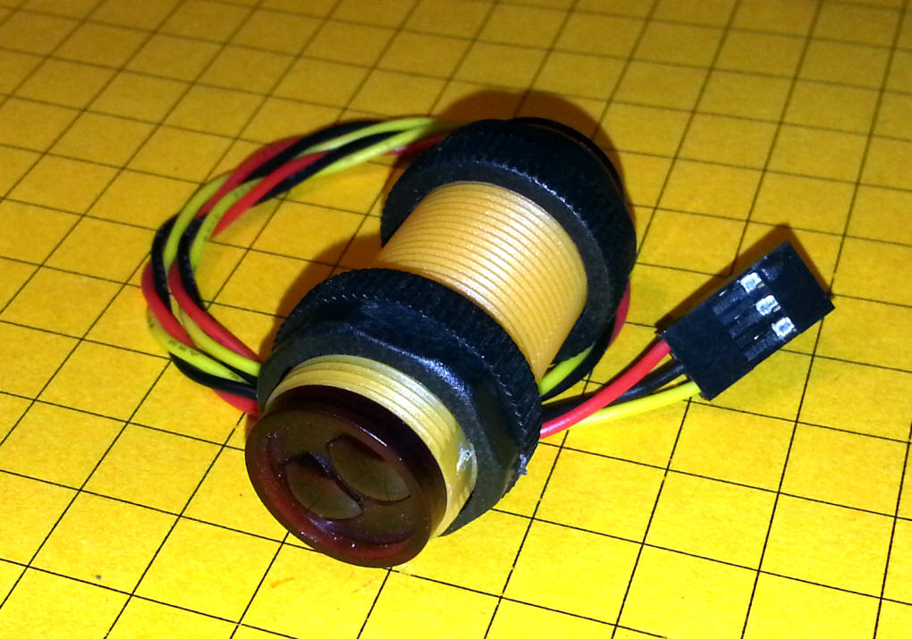
I purchased mine from SuntekStore - http://www.suntekstore.com/goods.php?id=14003450 The cost should be less than $10.00. This photo shows the sensor that I have been working with. It's three wires that terminate in a 3 pin plug. The two black nuts around the threaded body can be used for mounting.
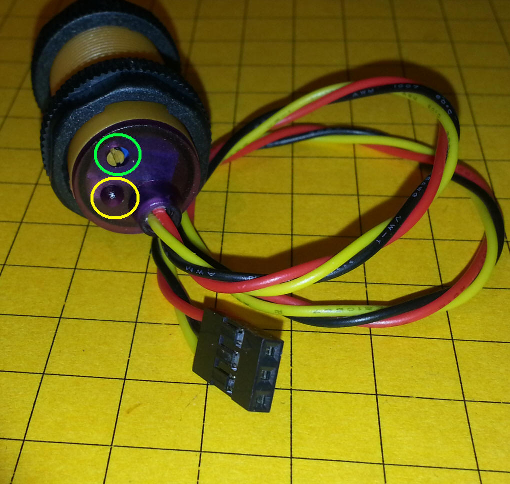
This photo shows the two areas at the front of the sensor that send and received the IR light.
The back of the sensor has an LED, circled in yellow, that shows if it is "seeing" reflected IR. If it does not see any reflection the LED is dark, if IR is detected it lights red. There is an adjustment screw, circled in green, that can be used to adjust the sensitivity of the unit. Turning the screw counter clockwise makes it less sensitive and turning it clockwise makes it more sensitive. For our purposes the screw should be turned five or ten times clockwise. Note that there is no stop when you turn the screw. Just turn it clockwise enough to get maximum sensitivity. You should hear a clicking sound when you reach the maximum setting.
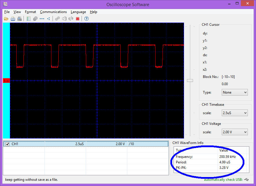
The unit emits IR pulses from one of the lenses at the front of the unit and detects them from the other. The pulses are at 200 KHz as shown in the oscilloscope screen below.
The sensor has a 3 wire cable coming from it. The red wire goes to the positive terminal of a 5 volt power source, the black wire is ground and the yellow wire is the sensor output. The output wire carries 5 volts when not sensing reflected IR and 0 volts when it is. The microcontroller in the circuit can easily detect and act upon this signal. |
| The Motor Controller The "intelligence" of the Cruise Control is shown in the schematic below. The power from the track pickups enters the circuit in the upper left. There is it goes through a single 2 amp diode. This protects the circuit from reverse polarity. Note that this circuit will only work in one direction. If the track power is in one direction the diode will pass the current and the unit will work. The opposite polarity will not pass and the unit will not operate. Make sure that you have the track pickups set up so that the train goes forward when the transformer is in the forward direction. A 7805 voltage regulator gives us a stable 5 volt supply for the rest of the circuit. The central component is a small PIC 12F683 processor. This is an 8 pin device that I have used in dozens of other projects. The output line from the IR sensor module connects to pin 6 on the PIC. The IR receiver that gets commands from the TV remote connects to pin 3. A high power Mosfet connects to pin 5 through a 1K resistor. The Mosfet varies the power that goes to the engine's motor by sending precisely timed pulses, called PWM, to the motor. This allows the circuit to run the motor at any speed from full stop to full speed ahead! A red LED, R4, lights when the IR module "sees" reflected infrared light.
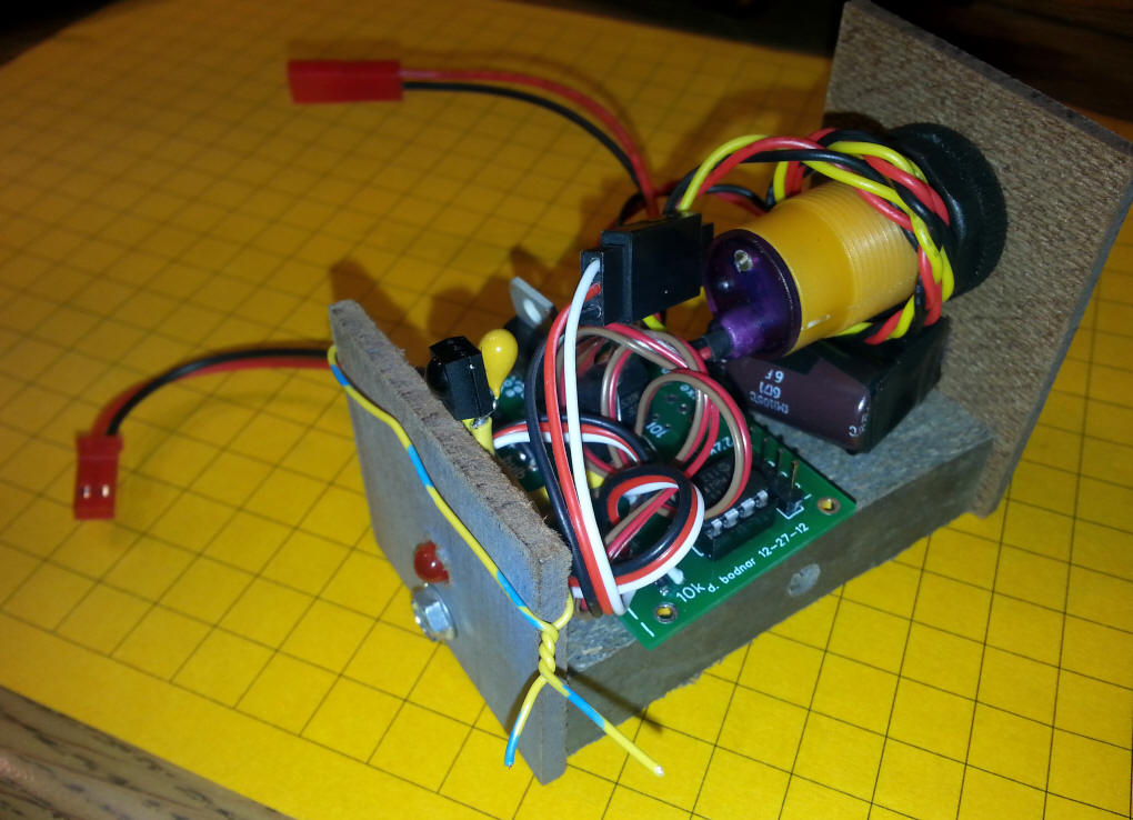
The circuit was built on a board that I normally use for a lighthouse or Morse code beacon. With very few modifications it can be used for the Cruise Control. <PHOTO of board & mods & bridge / cap board> |
| Software The software for the PIC 12F683 is written in PICBasicPro
|
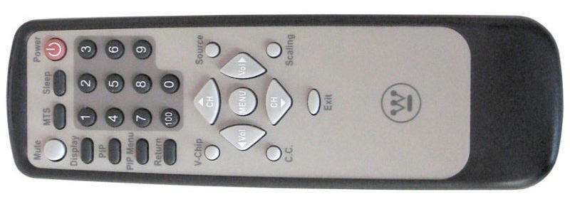
| TV Remote Speed Adjustment The circuit shown above utilizes a small TV remote receiver unit (connected to pin 3 on the PIC) that receives and interprets codes from a standard Sony-style TV remote. The remote control is used as follows:
|
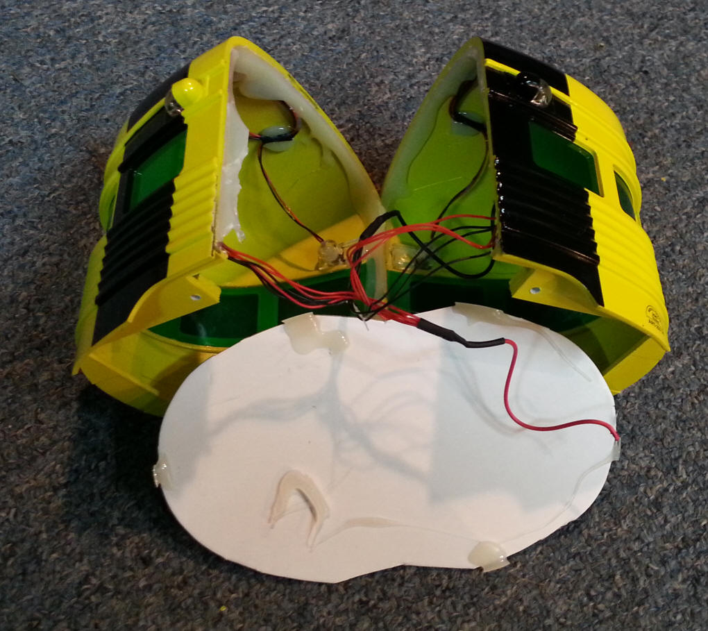
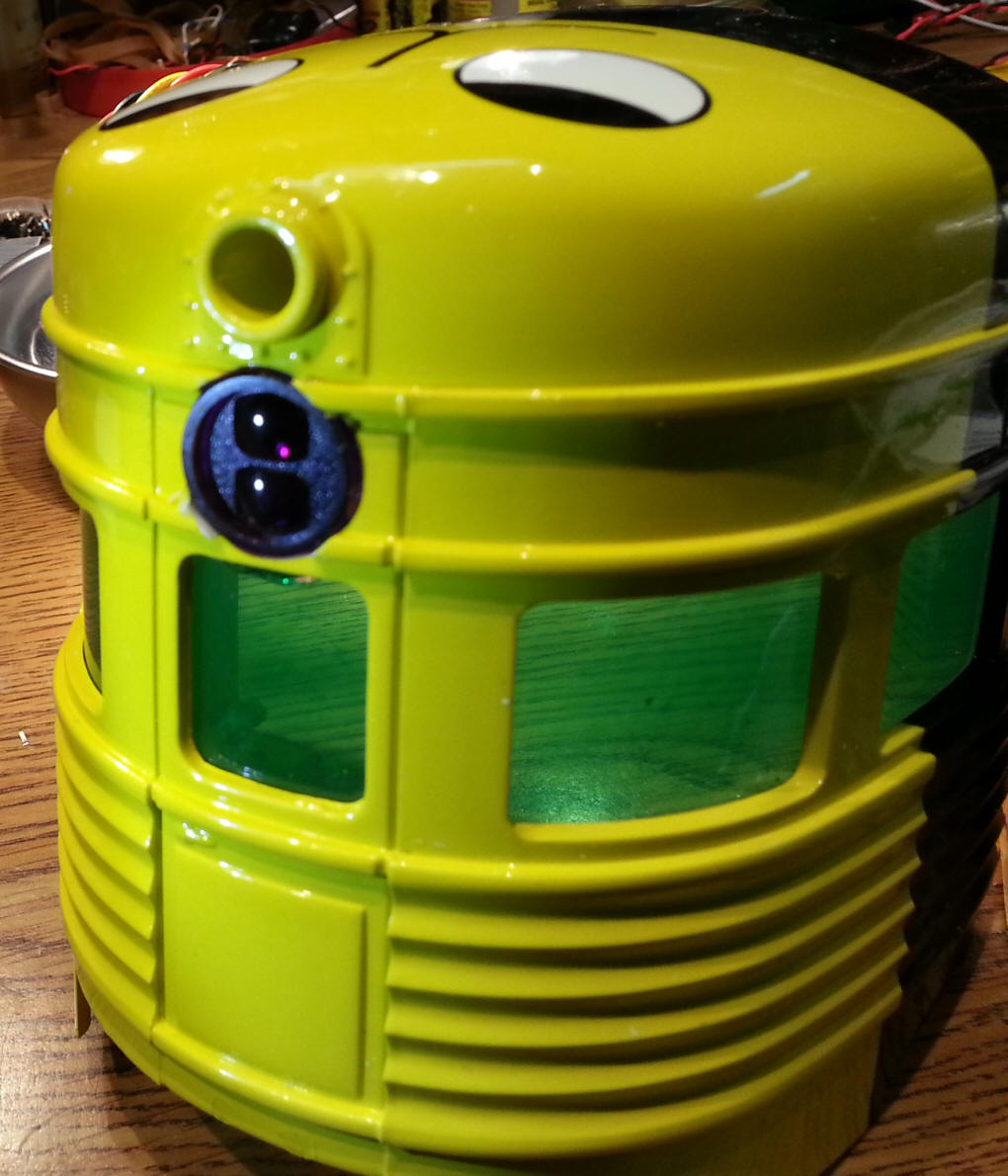
| Installation To give easy access to the Eggliner body I split it in half by firmly pulling the two sides apart. You can see some of the white glue that is used to hold the halves together.
Next I removed the three lights from the front half. Most times these can be gently pried out with a screwdriver. The side lights can be left in but it is much easier to work on the front half of the body if all three are removed.
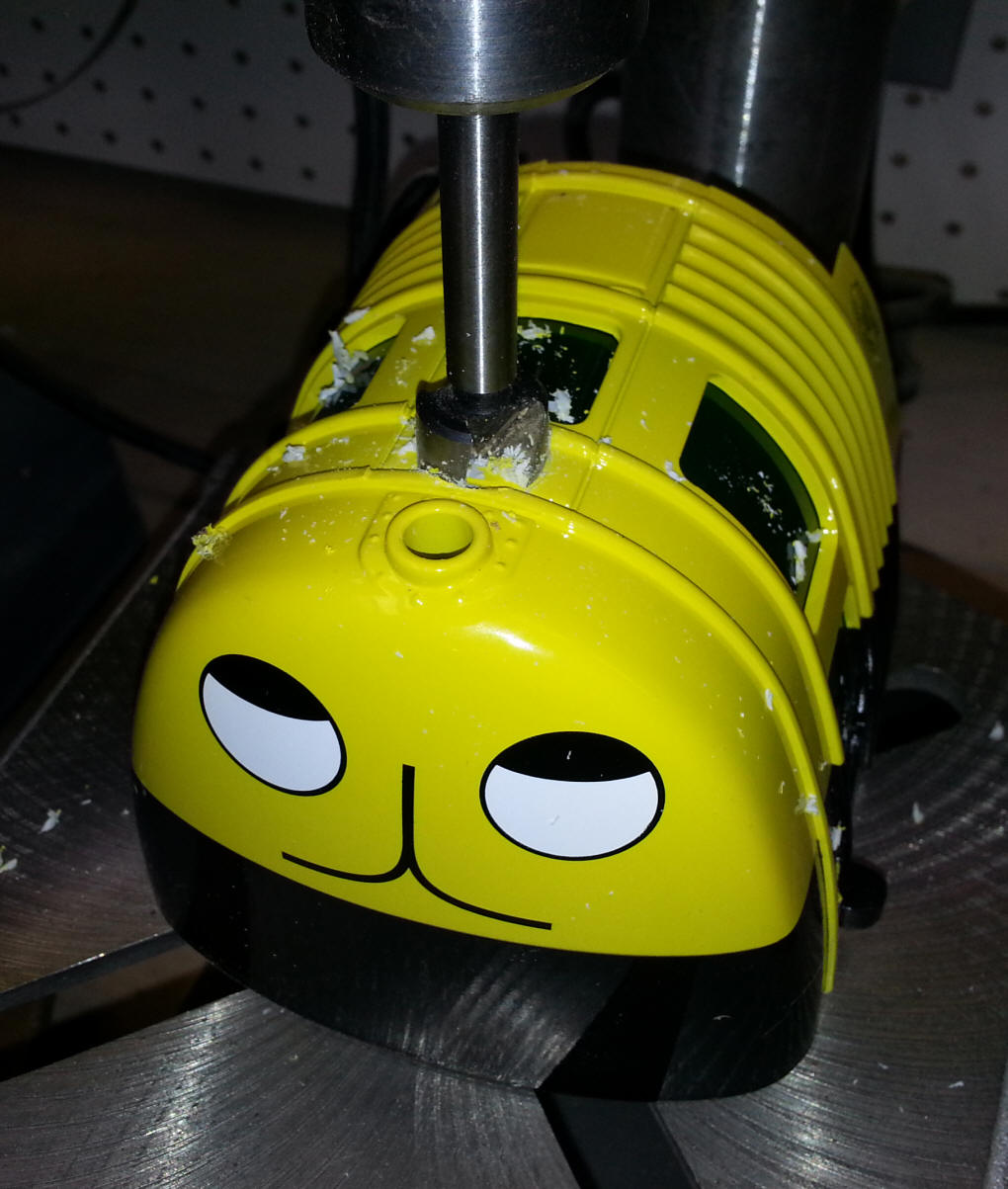
I drilled a 5/8" hole in the front of the Eggliner on a drill press using a Forstner bit. That is just a bit smaller than needed for the barrel of the sensor so I expanded it with a Dremel.
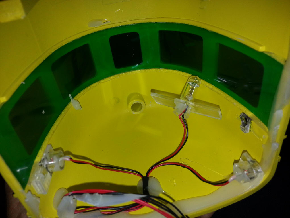
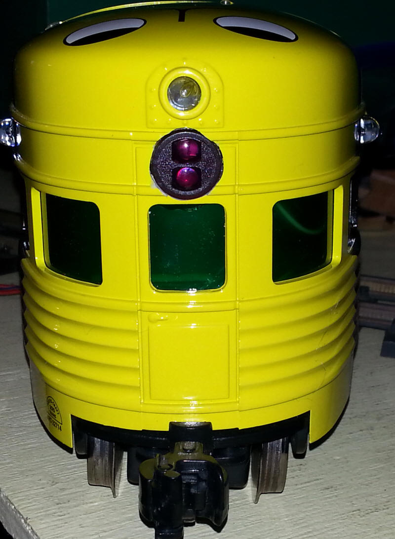
This photos shows that the two lenses on the sensor are aligned vertically. I found during testing that this orientation works best.
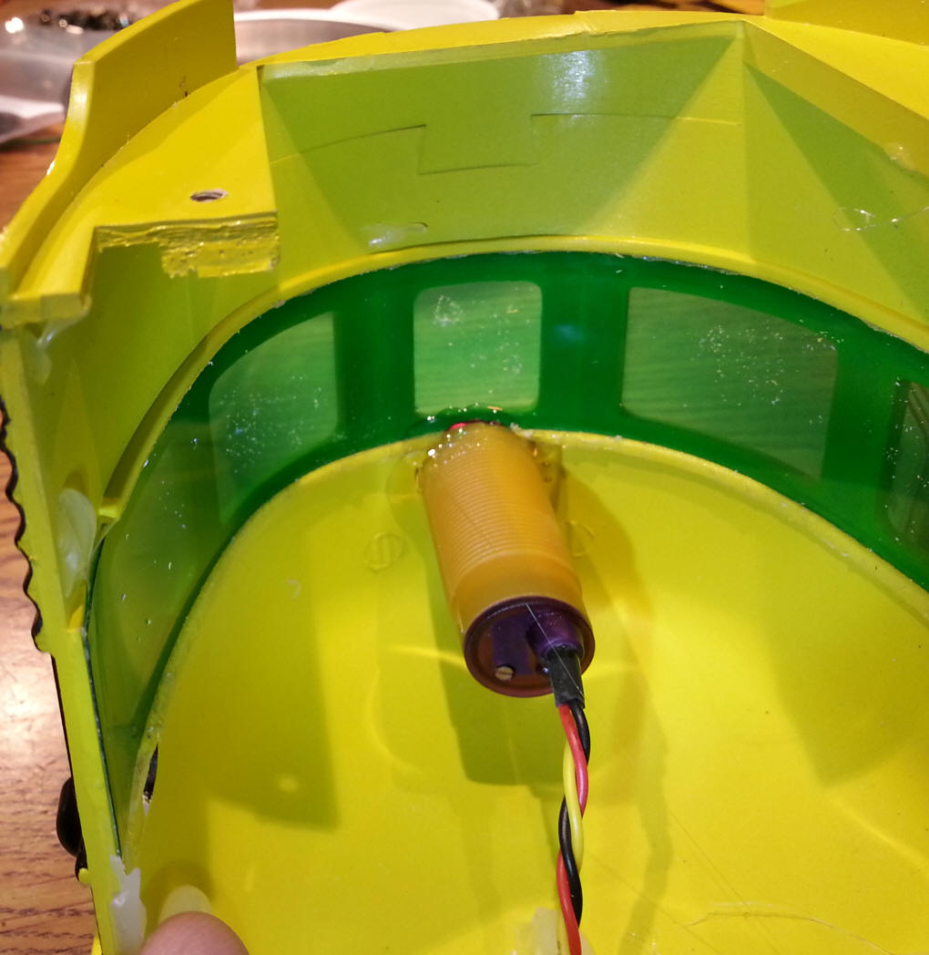
Hot melt glue was used inside of the body to secure the sensor.
Note that I did not use the existing hole from the front light but made a new hole below it. I suppose you could glue some support material into the other hole to facilitate centering the bit but I opted for a new hole. |
| Installation in a
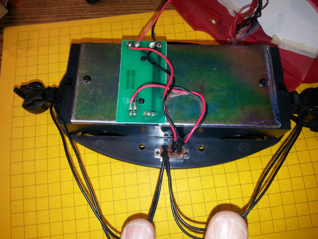
Newer Eggliner The wiring that is described here is for one of the newer Eggliners that have power plugs for battery operation at either end. Install the IR module as shown above. Open the Eggliner, unscrew and remove the metal weight and examine the existing wiring. You should see a small green circuit board with a number of wires soldered to it and a small switch.
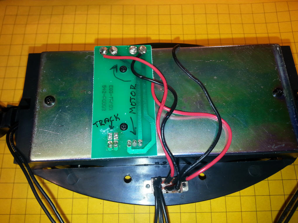
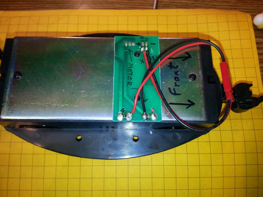
Remove the wiring from the pads marked "TRACK" in the photo below. Note that the interior lights wiring has been removed for now.
Remove all of the other wiring and the switch and wire the male and female JST connectors as shown below. Note that the female connector (with the larger plastic end) goes to the MOTOR connections and the smaller goes to the TRACK connections. Be careful to observe polarity wiring red and black ends as shown. If these wires are not wired correctly the unit will not work when the track power is set to run forward. The diode on the board only allows the engine to operate in the forward direction.
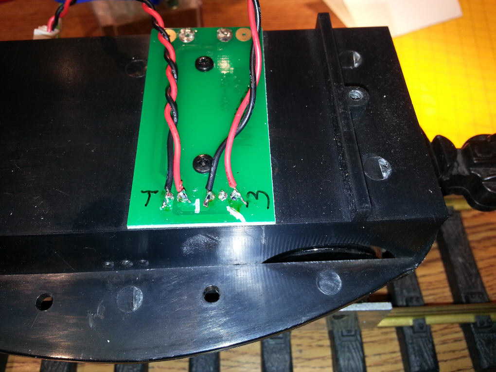
If you have an older Eggliner you can wire is as below. Note the two traces that have been cut at the bottom of the board.
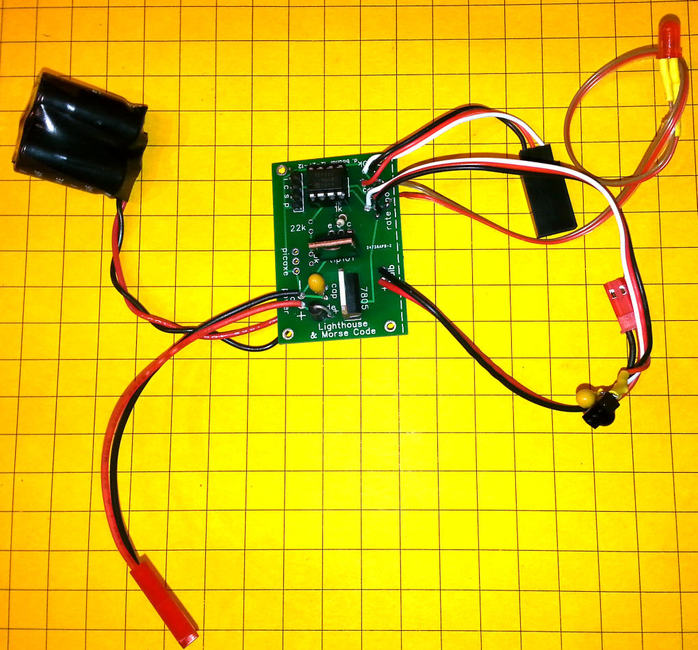
When you are done with the installation you can resolder the leads for the interior lights. The board and its components are shown below. The black object in the upper left is a pair of capacitors that helps to keep the board working when the engine runs over dirty track. These capacitors can be placed in any convenient place. The LED in the upper right is the tail light that comes on whenever the IR module detects reflected IR. The small black object in the lower right is the IR detector that "sees" codes from a Sony TV remote. It works best when mounted in the rear of the engine. The small dome on the detector should face out. There are two red plugs. The one in the lower left, a female connector, goes to the track power pickups. The red connector in the right center of the photo goes to the motor connections. The black connector to the right has three wires going to it, red, white and black. The orange IR module plugs into it. Make sure that the black and red wires line up - the white wire on the connector goes to the yellow wire on the module. You can plug it in backwards so be careful!
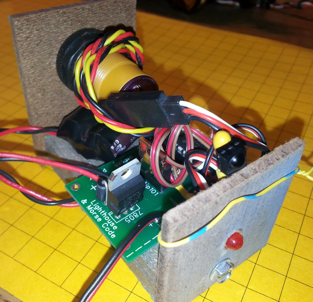
A wooden mount was built to hold the components in place during testing. The IR sensor module is the object to the left and the red LED and IR TV sensor is to the right.
The two red connectors have yet to be attached to the track pickups and motor. Note the two capacitors under the orange module.
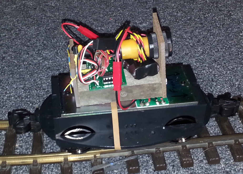
Here the test unit is installed on top of the Eggliner power unit.
|
|
|
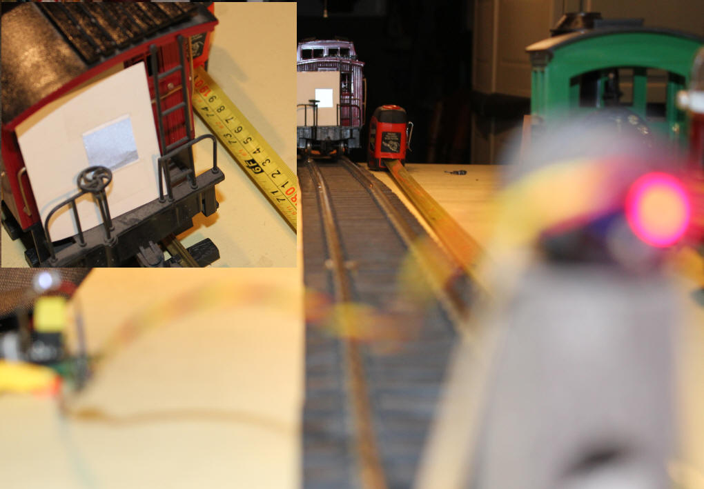
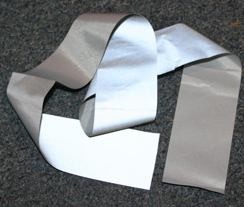
A Bit of Reflective Magic This time I am using a passive (non-powered) high tech reflective material that extends the range of the IR sensor dramatically as you can see in this photo. There is a small (approximately 1 square inch) piece of reflective fabric on a card on the back of the caboose. The sensor detects it up to six feet away!
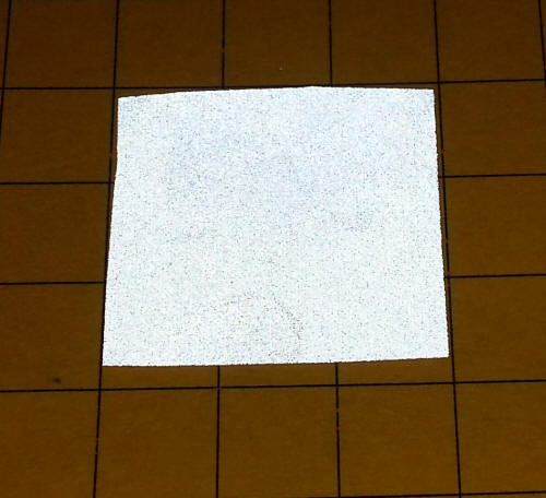
This material is available from a number of vendors on eBay. Just search for "reflective fabric" or "reflective tape". I ordered mine here: http://www.ebay.com/itm/3M-Scotchlite-Reflective-Tape-8910-sew-on-material-2-Fast-Shipping-/251355789971?pt=LH_DefaultDomain_0&hash=item3a85f8fa93 $5 / yard delivered The two photos below show the difference in brightness when shot without a flash (first photo) and with flash.
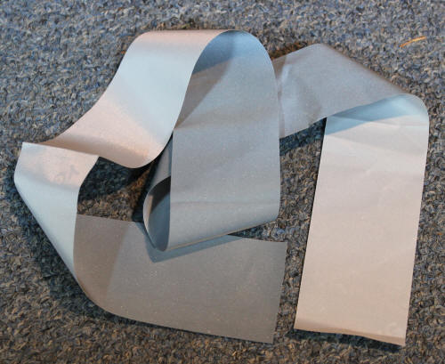
The piece below is what is at the back of the caboose. It is a little over 1" wide and a bit under 1" high.
|
| Going Further The circuit can be rewired so that the engine runs facing backwards. When in this mode it is designed to run at its slow speed when no IR is detected and speed up to its top speed when another engine comes up behind it.
|
| Conclusion The IR module makes installation of the unit much easier and works very well. The addition of a high and low speed adjustment via a TV remote also makes coordination speeds much easier.
|
| Another Idea! When I designed the original Eggliner with Cruise Control it was able to run facing either forward or backwards. By adding an optoisolator that was wired to detect the track polarity I had the Eggliner work as follows:
This was possible because the speed change was accomplished by inserting a resistor in series with the motor leads to slow the engine down. Resistors don't care about polarity and it worked equally well going forward or backwards. The new system uses a power transistor, a mosfet, to adjust the speed. Such transistors do care about polarity and will only work when the power is being supplied with one polarity. My first method of dealing with running the new Eggliners backwards so that the scooted ahead when approached from the rear, involved adding a 4PDT relay that switched both the track pickups and the motor wires. It worked but I kept thinking that there had to be a better way! That "better" way came to me the other day when I realized that it would be easier to add a second IR module to the Eggliner than to do all of the relay wiring that I had been using. I added the second sensor, connected it to an unused input on the 12F683 and changed the software so that pressing the MENU button on the TV remote switched it from the front sensor to the back one. SUCCESS!
|
 |
| 'IR Cruise Control using
Yellow IR Module on 12f683 '4-18-14 adding press MENU to toggle forward or backward running ' revised for use with 2 IR modules - forward & backward still via MENU option_reg.7=0 'turn on weak pull ups wpu = %00100010 'weak pull ups on pin GPIO.5 (Pin 2) only Include "modedefs.bas" ansel = 0 cmcon0 = 7 IRin var gpio.4 'pin 3 -from Vishay Module Serial_out var gpio.0 'pin 7 ' Motor con 1 NotUsed var gpio.3 'pin 4 IRModule var gpio.1 'pin 6 - orange gizmo - has internal pulse system IRModuleRear var gpio.5 ' pin 2 - 2nd orange gizmo TopSpeed var word 'speed when no reflected IR seen LowSpeed var word 'soeed when reflected IR seen PowerFlag var bit IRpulse_length var word(13) xx var byte Command Var Byte FRMode var byte '0 if normal, 1 if back sensor ChUp con 144''16 Changed to 1/4 top speed up/down ChDown con 145''17 and VolUp con 146''18 2/5 slow speed VolDown con 147''19 MENU con 224 Power con 149 Retrn con 187 One con 128 Two con 129 Three con 130 Four con 131 Five con 132 Six con 133 Seven con 134 Eight con 135 Nine con 136 Zero con 137 Powerr con 149 MENUU con 224 VChip con 142 Exxit con 99 IRState var bit 'forward or reverse running = if 0 forward, if 1 backwards IRState = 0 OSCCON = %01110000 ' Set to 8MHz Serout serial_out,n9600,[13,10,"d. bodnar Ver 4.1 -Menu for fwd/rev ",13,10] Serout serial_out,n9600,[13,10,"IR Cruise Control using Yellow IR Module on 12f683",13,10] gpio = %00111010 '3 & 4 inputs - others outputs DATA @0, 254 'set TopSpeed, byte 0 data @1, 0 'set TopSpeed, byte 1 DATA @2, 100 'set LowSpeed, byte 0 data @3, 0 'set LowSpeed, byte 1 data @4, 0 'remember normal or reverse running init: read 0, WORD TopSpeed read 2, WORD LowSpeed read 4, FRMode irstate=frmode serout serial_out,n9600,["IR Test 12F683",13,10] serout serial_out,n9600,["Top / Low = ", #TopSpeed," ",#LowSpeed,13,10] PowerFlag=1 Start: serout serial_out,n9600,["FR, IRS, mod1, mod2",#frmode, " ",#irstate," ",#irmodule," ",#irmodulerear,13,10] if PowerFlag=1 then if frmode = 0 then if irmodule =0 then 'pinc.4 = 0 then =1 if reflected seen ' serout serial_out,n9600,["0"]',13,10) hpwm motor, lowspeed, 2000 else hpwm motor, Topspeed, 2000 endif endif if frmode = 1 then if irmodulerear = 0 then ' serout serial_out,n9600,["1"] hpwm motor, topspeed, 2000 else hpwm motor, lowspeed, 2000 endif endif else hpwm motor, 0, 2000 endif gosub GetIR if command = one or command= two or command = four or command = five then serout serial_out,n9600,["IR =",#command," Top/Low = ",#topspeed," ",#lowspeed,13,10] endif if command=Power then PowerFlag=NOT PowerFlag if powerflag=0 then hpwm motor, 0, 2000 else hpwm motor, lowspeed, 2000 endif pause 500 endif if topspeed < lowspeed then lowspeed=topspeed if command=one then TopSpeed = TopSpeed + 1 if topspeed > 253 then topspeed = 255 endif write 0, WORD TopSpeed endif if command=Four then if topspeed > 1 then TopSpeed = TopSpeed - 1 if topspeed <=1 then topspeed = 0 endif write 0, WORD TopSpeed endif if command=two then LowSpeed = LowSpeed + 1 if lowspeed >topspeed then lowspeed=topspeed endif write 2, WORD LowSpeed endif if command=five then if lowspeed > 1 then LowSpeed = LowSpeed - 1 if lowspeed <=1 then lowspeed =0 endif write 2, WORD LowSpeed endif if command=Menu then irstate = not(irstate) FRMode=irstate write 4, frmode pause 500 endif goto Start: GetIR: Getstartbits: Pulsin IRin ,0,IRpulse_length(0) if IRpulse_length(0) < 400 then command=0 'goto getstartbits return Endif for xx=1 to 12 pulsin IRin,0,IRpulse_length(xx) next xx displaybits: if IRpulse_length(1) < 200 then Command.bit0 = 0 Else Command.bit0 = 1 endif if IRpulse_length(2) < 200 then Command.bit1 = 0 Else Command.bit1 = 1 endif if IRpulse_length(3) < 200 then Command.bit2 = 0 Else Command.bit2 = 1 endif if IRpulse_length(4) < 200 then Command.bit3 = 0 Else Command.bit3 = 1 endif if IRpulse_length(5) < 200 then Command.bit4 = 0 Else Command.bit4 = 1 endif if IRpulse_length(6) < 200 then Command.bit5 = 0 Else Command.bit5 = 1 endif if IRpulse_length(7) < 200 then Command.bit6 = 0 Else Command.bit6 = 1 endif if IRpulse_length(8) < 200 then Command.bit7 = 0 Else Command.bit7 = 1 Endif If Command.bit7 = 0 then 'Bit 7 is one of the device bits Command = Command + 1 Endif If Command = 10 then Command = 0 Endif return |
08M version for PICAXE - 08M2-IR-testV1-2-Numbers-Cruise-Control.bas
'd. bodnar 4-02-14
- |