Introduction
I recently came across an excellent
tutorial by Geoff Bunza in the Model Railroad Hobbyist Magazine
forum. It described how an
Arduino Pro Mini (a low cost Arduino board) could be wired and
programmed to respond to function keys on a DCC controller.
This opens up a wide world of control options for animations, sound
and other options on a DCC equipped model railroad.
I cobbled together a circuit based on Geoff's
article and plan on using it for a number of things on our
club modular layout. |
|
|
|
Hardware
The circuit is composed of a power supply section, an
optocoupler section and the Arduino. One pin on the Arduino
picks up the DCC data and the other 17 I/0 pins are connected to
LEDs.
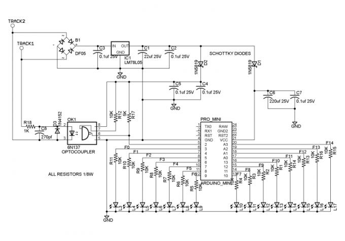
Power is picked up from the DCC powered track
and fed into a bridge rectifier and a voltage regulator as well as a
number of filtering elements. The
Optocoupler isolates the track voltage from the microcontroller.
The Arduino Mini used in this project
were purchased from
BangGood.com for
a bit over $3.00 each, delivered. They can be had for less but
I find that the ones from this vendor work well and get here in two
weeks or less. |
Test Builds
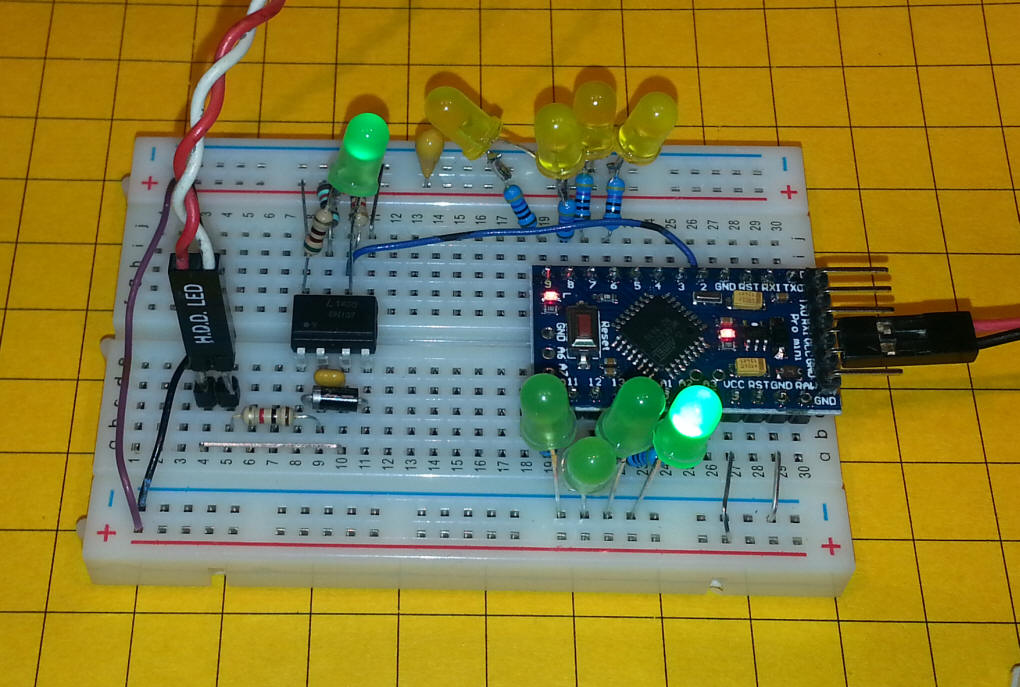
The first circuit I tried is shown here. The Arduino and
other components are mounted on a solderless breadboard.
The optocoupler is at left-center along with some filtering and pull
up resistors. The red/white wire goes to the DCC track.
Note that the power supply section is not included for this test.
Power is supplied to the Arduino by the plug to the far right that
goes to a 3.7 volt cell phone battery.
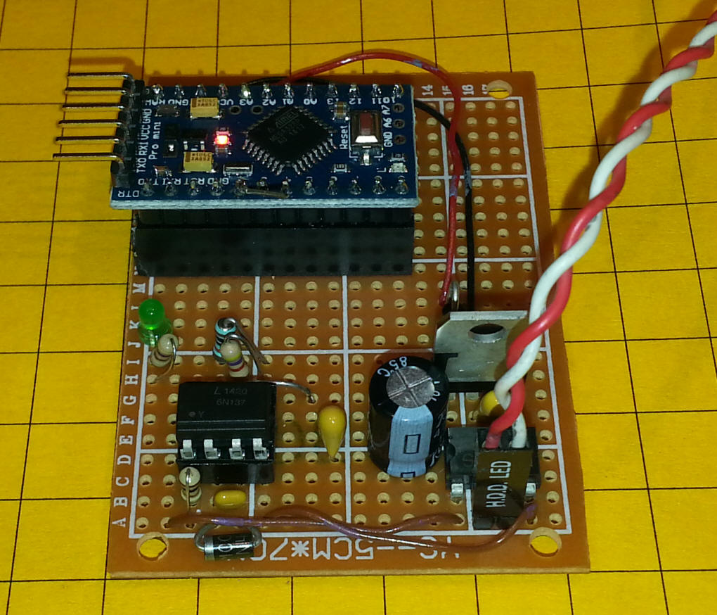
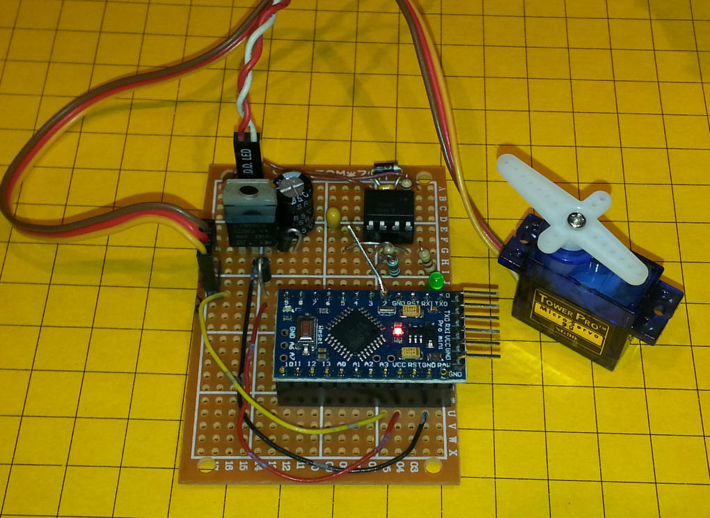
Here is the complete circuit. The
power from the DCC track still comes in via the red/white wires.
The other components in the upper left are a bridge rectifier, a
7805 voltage regulator (the big brother of the one Geoff used) and
some filtering caps.
The piece of bare wire hanging off of pin 2
on the Arduino is there to connect the output from the optocoupler
to my oscilloscope for testing.

|
Software Modifications
Geoff's software toggles the 17 LEDs attached to the Arduino by
pressing function buttons on the DCC controller.
Since I don't plan on using all 17 output pins
I modified the program to give the state of the 17 pins rather than
actually lighting them.
The code is here: (Please note
that I am not very skilled in programming the Arduino and there are
sure to be better ways to do what I have done but this does work for
my purposes!)
The library that I used (from Geoff) is
here:
DCC_Arduino/NmraDcc.zip
//BE VERY SURE to use
the NmraDcc.h library from Geoff's Zip file -- others on the web
WILL NOT work!
#include <NmraDcc.h>
#include <SoftwareSerial.h>
//for serial port on USB
byte rxPin = 0;
byte txPin = 1;
SoftwareSerial mySerial = SoftwareSerial(rxPin, txPin);
// Working 14 Function DCC Decoder DccAckPin not needed
int tim_delay = 500;
#define numleds 17
byte ledpins [] = {0,3,4,5,6,7,8,9,10,11,12,13,14,15,16,17,18,19};
const int FunctionPin0 = 3;
const int FunctionPin1 = 4;
const int FunctionPin2 = 5;
const int FunctionPin3 = 6;
const int FunctionPin4 = 7;
const int FunctionPin5 = 8;
const int FunctionPin6 = 9;
const int FunctionPin7 = 10;
const int FunctionPin8 = 11;
const int FunctionPin9 = 12;
const int FunctionPin10 = 13;
const int FunctionPin11 = 14; //A0
const int FunctionPin12 = 15; //A1
const int FunctionPin13 = 16; //A2
const int FunctionPin14 = 17; //A3
const int FunctionPin15 = 18; //A4
const int FunctionPin16 = 19; //A5
NmraDcc Dcc ;
DCC_MSG Packet ;
#define This_Decoder_Address 17
extern uint8_t Decoder_Address = This_Decoder_Address;
struct CVPair
{
uint16_t CV;
uint8_t Value;
};
CVPair FactoryDefaultCVs [] =
{
{CV_MULTIFUNCTION_PRIMARY_ADDRESS, This_Decoder_Address},
{CV_ACCESSORY_DECODER_ADDRESS_MSB, 0},
{CV_MULTIFUNCTION_EXTENDED_ADDRESS_MSB, 0},
{CV_MULTIFUNCTION_EXTENDED_ADDRESS_LSB, 0},
};
uint8_t FactoryDefaultCVIndex = 0;
void notifyCVResetFactoryDefault()
{
// Make FactoryDefaultCVIndex non-zero and equal to num CV's to be
reset
// to flag to the loop() function that a reset to Factory Defaults
needs to be done
FactoryDefaultCVIndex = sizeof(FactoryDefaultCVs)/sizeof(CVPair);
};
void setup()
{
pinMode(rxPin, INPUT);
pinMode(txPin, OUTPUT);
mySerial.begin(9600);
// initialize the digital pins as an outputs
for (int i=1; i<= numleds; i++) {
pinMode(ledpins[i], OUTPUT);
digitalWrite(ledpins[i], LOW);
}
for (int i=1; i<= numleds; i++) {
digitalWrite(ledpins[i], HIGH);
delay (tim_delay/10);
}
delay( tim_delay);
for (int i=1; i<= numleds; i++) {
digitalWrite(ledpins[i], LOW);
delay (tim_delay/10);
}
delay( tim_delay);
// Setup which External Interrupt, the Pin it's associated with that
we're using and enable the Pull-Up
Dcc.pin(0, 2, 0);
// Call the main DCC Init function to enable the DCC Receiver
Dcc.init( MAN_ID_DIY, 100, FLAGS_MY_ADDRESS_ONLY, 0 );
}
void loop()
{
// You MUST call the NmraDcc.process() method frequently from the
Arduino loop() function for correct library operation
Dcc.process();
if( FactoryDefaultCVIndex && Dcc.isSetCVReady())
{
FactoryDefaultCVIndex--; // Decrement first as initially it is the
size of the array
Dcc.setCV( FactoryDefaultCVs[FactoryDefaultCVIndex].CV,
FactoryDefaultCVs[FactoryDefaultCVIndex].Value);
}
}
extern void notifyDccFunc( uint16_t Addr, uint8_t FuncNum, uint8_t
FuncState) {
if (FuncNum==1) { //Function Group 1 F0 F4 F3 F2 F1
digitalWrite( FunctionPin0, (FuncState&0x10)>>4 );
digitalWrite( FunctionPin1, (FuncState&0x01 ));
digitalWrite( FunctionPin2, (FuncState&0x02)>>1 );
digitalWrite( FunctionPin3, (FuncState&0x04)>>2 );
digitalWrite( FunctionPin4, (FuncState&0x08)>>3 );
}
else if (FuncNum==2) { //Function Group 1 S FFFF == 1 F8 F7 F6 F5 &
== 0 F12 F11 F10 F9 F8
if ((FuncState & 0x10)==0x10) {
digitalWrite( FunctionPin5, (FuncState&0x01 ));
digitalWrite( FunctionPin6, (FuncState&0x02)>>1 );
digitalWrite( FunctionPin7, (FuncState&0x04)>>2 );
digitalWrite( FunctionPin8, (FuncState&0x08)>>3 );
}
else {
digitalWrite( FunctionPin9, (FuncState&0x01 ));
digitalWrite( FunctionPin10, (FuncState&0x02)>>1 );
digitalWrite( FunctionPin11, (FuncState&0x04)>>2 );
digitalWrite( FunctionPin12, (FuncState&0x08)>>3 );
}
}
else if (FuncNum==3) { //Function Group 2 FuncState == F20-F13
Function Control
digitalWrite( FunctionPin13, (FuncState&0x01 ));
digitalWrite( FunctionPin14, (FuncState&0x02)>>1 );
digitalWrite( FunctionPin15, (FuncState&0x04)>>2 );
digitalWrite( FunctionPin16, (FuncState&0x08)>>3 );
}
// this string is the Function #
mySerial.print(" 012345678901234");
mySerial.println(" ");
// this string is the Arduino Pin #
mySerial.print("12345678901234567");
mySerial.println(" ");
for (int i=1; i<= numleds; i++) {
mySerial.print(digitalRead(i));
}
mySerial.println(" ");
}
The code modifications that I made are in
bold. Since the normal serial I/O is interrupt driven I
had to use a software serial library as the other interferes with
reliably gathering data from the DCC pickup. |
| |
Program Output
Once the program is installed open the serial terminal
click the small magnifying glass in the upper right corner
Each time a function key is pressed you should
see something like this:
012345678901234 '0--9 then 10--14 the
10's digit is not shown
12345678901234567 '1-9 then 10--17 the
10's digit is not shown
10000000000001100 ' the state of the
pins is in this line
012345678901234
12345678901234567
10000000000011100
012345678901234
12345678901234567
11000000000001100
Each set of three lines makes up one entry.
The first set of numbers is the function key on the DCC controller.
The second corresponds to the output pin on the Arduino and the last
line is the state of those pins. You will note that the first
two lines are always the same. The third line changes as the
function keys are turned on or off.
|
Next Steps
Now that I have a reliable hardware / software platform I plan
on experimenting with using this to drive several servos. I
will likely use 4 pins for each servo. One output pin to drive
the servo and three input pins (from the DCC routines) to send it to
three different positions that are set in software - left, center
and right.I also may incrementally
move the servos by pressing keys using one key to move left, one to
move right and one to center it. Lots of possibilities!
|
Conclusion
I would like to thank Geoff Bunza for bringing the idea of using
this inexpensive Arduino circuit to give us the ability to control
animations and such with standard DCC equipment. So far I have
had a great time experimenting and will update this page as things
progress - stop back often!If you
have any questions please contact me via email at
dave@davebodnar.com
|
Servo Test #1
The test program for servo operation is below - it is still a
"work-in-progress" but it does function.
Hardware: connect
a servo to a 3 pin header that is attached to ground, +5 volts, and
pin A3. This is a good place to note that the 7805 used in
this project can handle enough current to operate several servos.
The smaller version (78L05) can only supply 100 ma, barely enough
for the circuit and a servo.
Operation:
- Press F7 to
center the servo - be sure to "unclick" F7 if it latches as most
do
- Press F6 to
move the servo all the way to the left - be sure to "unclick" F6
if it latches as most do
- Press F8 to
move the servo all the way to the right - be sure to "unclick"
F8 if it latches as most do
#include <NmraDcc.h>
#include <SoftwareSerial.h>
//for serial port on USB
byte rxPin = 0;
byte txPin = 1;
SoftwareSerial mySerial = SoftwareSerial(rxPin, txPin);
// Working 14 Function DCC Decoder DccAckPin not needed
int tim_delay = 500;
#define numleds 16 //using 17th as servo control pin (A3)
#include <Servo.h>
Servo myservo; // create servo object to control a servo
// a maximum of eight servo objects can be created
int pos = 0; // variable to store the servo position
byte ledpins [] = {0,3,4,5,6,7,8,9,10,11,12,13,14,15,16,17,18,19};
const int FunctionPin0 = 3;
const int FunctionPin1 = 4;
const int FunctionPin2 = 5;
const int FunctionPin3 = 6;
const int FunctionPin4 = 7;
const int FunctionPin5 = 8;
const int FunctionPin6 = 9;
const int FunctionPin7 = 10;
const int FunctionPin8 = 11;
const int FunctionPin9 = 12;
const int FunctionPin10 = 13;
const int FunctionPin11 = 14; //A0
const int FunctionPin12 = 15; //A1
const int FunctionPin13 = 16; //A2
const int FunctionPin14 = 17; //A3
const int FunctionPin15 = 18; //A4
const int FunctionPin16 = 19; //A5
NmraDcc Dcc ;
DCC_MSG Packet ;
#define This_Decoder_Address 17
extern uint8_t Decoder_Address = This_Decoder_Address;
struct CVPair
{
uint16_t CV;
uint8_t Value;
};
CVPair FactoryDefaultCVs [] =
{
{CV_MULTIFUNCTION_PRIMARY_ADDRESS, This_Decoder_Address},
{CV_ACCESSORY_DECODER_ADDRESS_MSB, 0},
{CV_MULTIFUNCTION_EXTENDED_ADDRESS_MSB, 0},
{CV_MULTIFUNCTION_EXTENDED_ADDRESS_LSB, 0},
};
uint8_t FactoryDefaultCVIndex = 0;
void notifyCVResetFactoryDefault()
{
// Make FactoryDefaultCVIndex non-zero and equal to num CV's to be
reset
// to flag to the loop() function that a reset to Factory Defaults
needs to be done
FactoryDefaultCVIndex = sizeof(FactoryDefaultCVs)/sizeof(CVPair);
};
void setup()
{
myservo.attach(A3); // attaches the servo on pin A3 to the servo
object
pinMode(rxPin, INPUT);
pinMode(txPin, OUTPUT);
mySerial.begin(9600);
// initialize the digital pins as an outputs
for (int i=1; i<= numleds; i++) {
pinMode(ledpins[i], OUTPUT);
digitalWrite(ledpins[i], LOW);
}
for (int i=1; i<= numleds; i++) {
digitalWrite(ledpins[i], HIGH);
delay (tim_delay/10);
}
delay( tim_delay);
for (int i=1; i<= numleds; i++) {
digitalWrite(ledpins[i], LOW);
delay (tim_delay/10);
}
delay( tim_delay);
// Setup which External Interrupt, the Pin it's associated with that
we're using and enable the Pull-Up
Dcc.pin(0, 2, 0);
// Call the main DCC Init function to enable the DCC Receiver
Dcc.init( MAN_ID_DIY, 100, FLAGS_MY_ADDRESS_ONLY, 0 );
}
void loop()
{
// You MUST call the NmraDcc.process() method frequently from the
Arduino loop() function for correct library operation
Dcc.process();
if( FactoryDefaultCVIndex && Dcc.isSetCVReady())
{
FactoryDefaultCVIndex--; // Decrement first as initially it is the
size of the array
Dcc.setCV( FactoryDefaultCVs[FactoryDefaultCVIndex].CV,
FactoryDefaultCVs[FactoryDefaultCVIndex].Value);
}
}
extern void notifyDccFunc( uint16_t Addr, uint8_t FuncNum, uint8_t
FuncState) {
if (FuncNum==1) { //Function Group 1 F0 F4 F3 F2 F1
digitalWrite( FunctionPin0, (FuncState&0x10)>>4 );
digitalWrite( FunctionPin1, (FuncState&0x01 ));
digitalWrite( FunctionPin2, (FuncState&0x02)>>1 );
digitalWrite( FunctionPin3, (FuncState&0x04)>>2 );
digitalWrite( FunctionPin4, (FuncState&0x08)>>3 );
}
else if (FuncNum==2) { //Function Group 1 S FFFF == 1 F8 F7 F6 F5 &
== 0 F12 F11 F10 F9 F8
if ((FuncState & 0x10)==0x10) {
digitalWrite( FunctionPin5, (FuncState&0x01 ));
digitalWrite( FunctionPin6, (FuncState&0x02)>>1 );
digitalWrite( FunctionPin7, (FuncState&0x04)>>2 );
digitalWrite( FunctionPin8, (FuncState&0x08)>>3 );
}
else {
digitalWrite( FunctionPin9, (FuncState&0x01 ));
digitalWrite( FunctionPin10, (FuncState&0x02)>>1 );
digitalWrite( FunctionPin11, (FuncState&0x04)>>2 );
digitalWrite( FunctionPin12, (FuncState&0x08)>>3 );
}
}
else if (FuncNum==3) { //Function Group 2 FuncState == F20-F13
Function Control
digitalWrite( FunctionPin13, (FuncState&0x01 ));
digitalWrite( FunctionPin14, (FuncState&0x02)>>1 );
digitalWrite( FunctionPin15, (FuncState&0x04)>>2 );
digitalWrite( FunctionPin16, (FuncState&0x08)>>3 );
}
// this string is the Function #
mySerial.print(" 012345678901234");
mySerial.println(" ");
// this string is the Arduino Pin #
mySerial.print("12345678901234567");
mySerial.println(" ");
for (int i=1; i<= numleds; i++) {
mySerial.print(digitalRead(i));
}
mySerial.println(" ");
//Servo Test - if F7 is pressed, center servo to position 90
if (digitalRead(10)==1){
pos=90;
myservo.write(pos);
}
//Servo Test - if F6 is pressed, servo left to position 0
if (digitalRead(9)==1){
pos=0;
myservo.write(pos);
}
//Servo Test - if F8 is pressed, servo right to position 180
if (digitalRead(11)==1){
pos=180;
myservo.write(pos);
}
}
|
Servo Test #2
The test program for servo operation is below - it is still a
"work-in-progress" but it does function.
Hardware: connect
a servo to a 3 pin header that is attached to ground, +5 volts, and
pin A3. This is a good place to note that the 7805 used in
this project can handle enough current to operate several servos.
The smaller version (78L05) can only supply 100 ma, barely enough
for the circuit and a servo.
Operation:
- Press F7 to
center the servo - be sure to "unclick" F7 if it latches as most
do
- Press F6 to
move the servo incrementally to the left - be sure to "unclick"
F6 if it latches as most do
- Press F8 to
move the servo incrementally to the right - be sure to "unclick"
F8 if it latches as most do
#include <NmraDcc.h>
#include <SoftwareSerial.h>
//for serial port on USB
byte rxPin = 0;
byte txPin = 1;
SoftwareSerial mySerial = SoftwareSerial(rxPin, txPin);
// Working 14 Function DCC Decoder DccAckPin not needed
int tim_delay = 500;
#define numleds 16 //using 17th as servo control pin (A3)
#include <Servo.h>
Servo myservo; // create servo object to control a servo
// a maximum of eight servo objects can be created
int pos = 90; // variable to store the servo position
byte ledpins [] = {0,3,4,5,6,7,8,9,10,11,12,13,14,15,16,17,18,19};
const int FunctionPin0 = 3;
const int FunctionPin1 = 4;
const int FunctionPin2 = 5;
const int FunctionPin3 = 6;
const int FunctionPin4 = 7;
const int FunctionPin5 = 8;
const int FunctionPin6 = 9;
const int FunctionPin7 = 10;
const int FunctionPin8 = 11;
const int FunctionPin9 = 12;
const int FunctionPin10 = 13;
const int FunctionPin11 = 14; //A0
const int FunctionPin12 = 15; //A1
const int FunctionPin13 = 16; //A2
const int FunctionPin14 = 17; //A3
const int FunctionPin15 = 18; //A4
const int FunctionPin16 = 19; //A5
NmraDcc Dcc ;
DCC_MSG Packet ;
#define This_Decoder_Address 17
extern uint8_t Decoder_Address = This_Decoder_Address;
struct CVPair
{
uint16_t CV;
uint8_t Value;
};
CVPair FactoryDefaultCVs [] =
{
{CV_MULTIFUNCTION_PRIMARY_ADDRESS, This_Decoder_Address},
{CV_ACCESSORY_DECODER_ADDRESS_MSB, 0},
{CV_MULTIFUNCTION_EXTENDED_ADDRESS_MSB, 0},
{CV_MULTIFUNCTION_EXTENDED_ADDRESS_LSB, 0},
};
uint8_t FactoryDefaultCVIndex = 0;
void notifyCVResetFactoryDefault()
{
// Make FactoryDefaultCVIndex non-zero and equal to num CV's to be
reset
// to flag to the loop() function that a reset to Factory Defaults
needs to be done
FactoryDefaultCVIndex = sizeof(FactoryDefaultCVs)/sizeof(CVPair);
};
void setup()
{
myservo.attach(A3); // attaches the servo on pin A3 to the servo
object
pinMode(rxPin, INPUT);
pinMode(txPin, OUTPUT);
mySerial.begin(9600);
// initialize the digital pins as an outputs
for (int i=1; i<= numleds; i++) {
pinMode(ledpins[i], OUTPUT);
digitalWrite(ledpins[i], LOW);
}
for (int i=1; i<= numleds; i++) {
digitalWrite(ledpins[i], HIGH);
delay (tim_delay/10);
}
delay( tim_delay);
for (int i=1; i<= numleds; i++) {
digitalWrite(ledpins[i], LOW);
delay (tim_delay/10);
}
delay( tim_delay);
// Setup which External Interrupt, the Pin it's associated with that
we're using and enable the Pull-Up
Dcc.pin(0, 2, 0);
// Call the main DCC Init function to enable the DCC Receiver
Dcc.init( MAN_ID_DIY, 100, FLAGS_MY_ADDRESS_ONLY, 0 );
}
void loop()
{
myservo.write(pos);
// delay (15);
// You MUST call the NmraDcc.process() method frequently from the
Arduino loop() function for correct library operation
Dcc.process();
if( FactoryDefaultCVIndex && Dcc.isSetCVReady())
{
FactoryDefaultCVIndex--; // Decrement first as initially it is the
size of the array
Dcc.setCV( FactoryDefaultCVs[FactoryDefaultCVIndex].CV,
FactoryDefaultCVs[FactoryDefaultCVIndex].Value);
}
}
extern void notifyDccFunc( uint16_t Addr, uint8_t FuncNum, uint8_t
FuncState) {
if (FuncNum==1) { //Function Group 1 F0 F4 F3 F2 F1
digitalWrite( FunctionPin0, (FuncState&0x10)>>4 );
digitalWrite( FunctionPin1, (FuncState&0x01 ));
digitalWrite( FunctionPin2, (FuncState&0x02)>>1 );
digitalWrite( FunctionPin3, (FuncState&0x04)>>2 );
digitalWrite( FunctionPin4, (FuncState&0x08)>>3 );
}
else if (FuncNum==2) { //Function Group 1 S FFFF == 1 F8 F7 F6 F5 &
== 0 F12 F11 F10 F9 F8
if ((FuncState & 0x10)==0x10) {
digitalWrite( FunctionPin5, (FuncState&0x01 ));
digitalWrite( FunctionPin6, (FuncState&0x02)>>1 );
digitalWrite( FunctionPin7, (FuncState&0x04)>>2 );
digitalWrite( FunctionPin8, (FuncState&0x08)>>3 );
}
else {
digitalWrite( FunctionPin9, (FuncState&0x01 ));
digitalWrite( FunctionPin10, (FuncState&0x02)>>1 );
digitalWrite( FunctionPin11, (FuncState&0x04)>>2 );
digitalWrite( FunctionPin12, (FuncState&0x08)>>3 );
}
}
else if (FuncNum==3) { //Function Group 2 FuncState == F20-F13
Function Control
digitalWrite( FunctionPin13, (FuncState&0x01 ));
digitalWrite( FunctionPin14, (FuncState&0x02)>>1 );
digitalWrite( FunctionPin15, (FuncState&0x04)>>2 );
digitalWrite( FunctionPin16, (FuncState&0x08)>>3 );
}
// this string is the Function #
// mySerial.print(" 012345678901234");
// mySerial.println(" ");
// this string is the Arduino Pin #
// mySerial.print("12345678901234567");
// mySerial.println(" ");
for (int i=1; i<= numleds; i++) {
// mySerial.print(digitalRead(i));
}
// mySerial.println(" ");
//Servo Test - if F7 is pressed, center servo to position 90
if (digitalRead(10)==1){
pos=90;
mySerial.println(pos);
}
//Servo Test - if F6 is pressed, servo left to by 5's
if (digitalRead(9)==1){
if (pos >=5 ){ //don't decrement if it takes us below zero
pos=pos-5;
}
mySerial.println(pos);
}
//Servo Test - if F8 is pressed, servo right by 5's
if (digitalRead(11)==1){
if (pos <= 175){ //don't increment if it takes us over 189
pos=pos+5;
}
mySerial.println(pos);
}
}
|
| |