|
|
|
|
Introduction This project is designed to give those operators a simple wireless throttle that will control those non-DCC locomotives & trolleys. The throttle will control up to three trains on three loops. Each receiver can be set to receive commands for station 1, station 2 or station 3. |
|
|
|
|
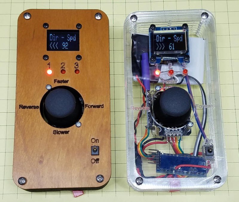
| Controlling the Trains The throttle has only a joystick to change the selected train, train speed and train direction. Pressing the joystick straight down for a short time will change from one train to the next as indicated by one of the three red LEDs being illuminated. Moving the joystick in an upward direction increases speed and moving it downward decreases the speed for the selected channel. A slight movement up or down speeds or slows the train by small increments. Pressing the stick full up or down changes the speed very rapidly. The speed varies from 0 (zero) to 255 and is displayed on the screen. Moving the joystick right or left changes the direction of travel of the selected train. The direction is shown on the display by either displaying <<< or >>> To stop all trains press the joystick straight down for 2 seconds. When you release it the train speed will drop to zero for all three channels. |
|
|
Throttle Construction These parts are used to build the throttle
|
|
|
Throttle Schematic Note that A4 and A5, which connect to the OLED display, are not on the side edges of the Pro Mini but either on the short edge or a bit inside of the edge with the other analog pins (A2, A3, etc).
|
|
|
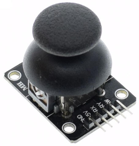
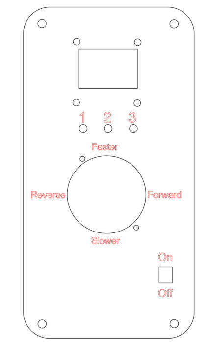
Transmitter Case I cut the front of the transmitter case on a laser cutter, the design is shown here. Note that only two screws are used for the joystick. This is due to its design not being symmetrical. The case can be cut from acrylic or plywood. The OLED display is at the top, the 3 channel selection LEDs are below it and the joystick is at the center. The on/off switch is in the lower right. Any SPST toggle switch can be used. |
 |
|
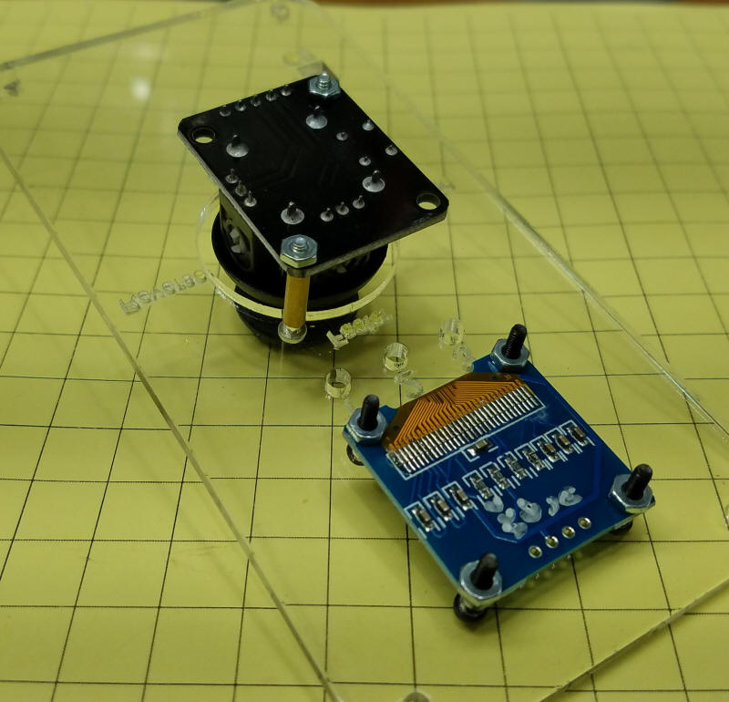
The joystick is mounted with two 3/4" x 2-56
bolts that are passed through two 1/2" x 1/8" brass tubing spacers
that hold the joystick in the proper position. (the standoffs
are indicated by the red arrows)
The OLED display is attached to the faceplate with four 1/2" x 2-56 bolts & nuts.
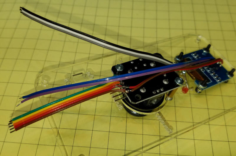
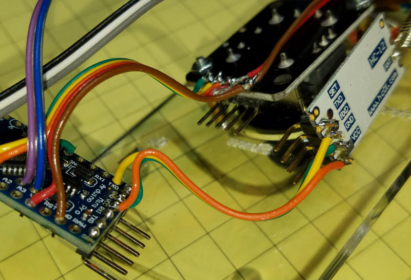
This photo shows the wiring that I did before connecting things to the Arduino. The 5 conductor wire (green, yellow, orange, red, brown) goes to the joystick. The 3 conductor wire (black, white, grey) goes to the anodes of the 3mm LEDs. The two conductor wire (blue, purple) goes to the data lines of the OLED display. There is also a two conductor wire (red, brown) that jumpers the VCC and ground from the joystick to the OLED display. The 3 cathodes of the LEDs are joined together and connected to the ground wire on the OLED display through a 470 ohm resistor.
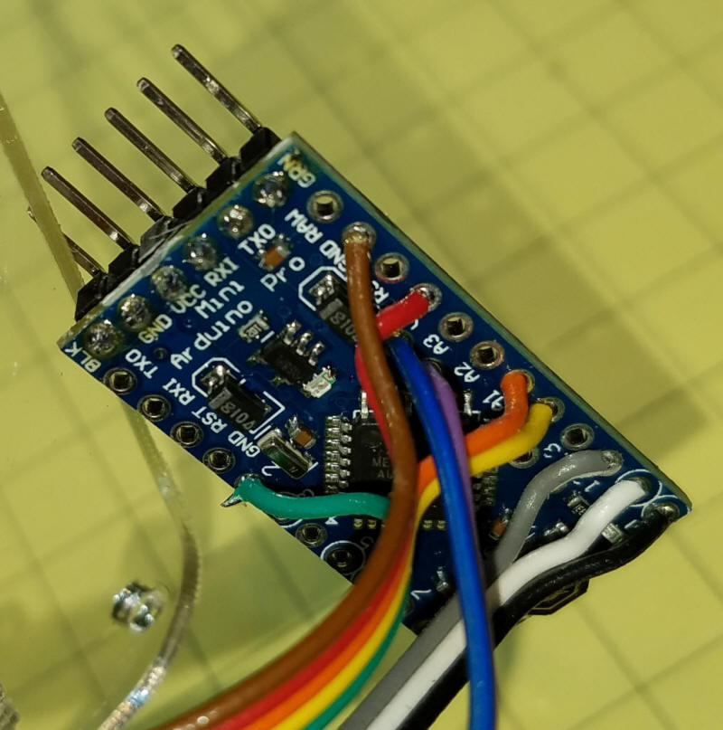
The connections to the Arduino are shown here. They are identical to what is shown in the schematic. Note that the blue and purple wires from the OLED display go to two holes in from the edge that has A2 an A3.
The connections from the HC-12 transceiver are done next. Only three connections are needed. VCC, ground and RX on the HC-12 to TX on the Arduino.
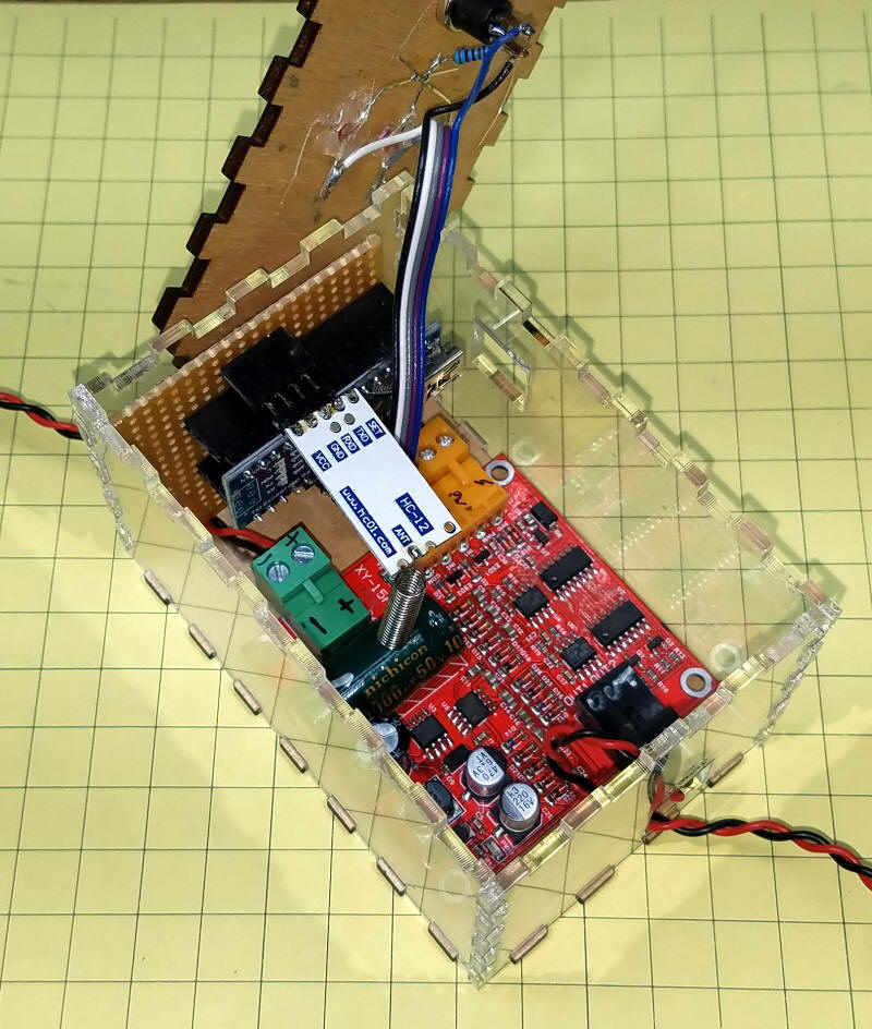
The completed throttle parts can be seen
through the acrylic case.
Back View:
|
|
|
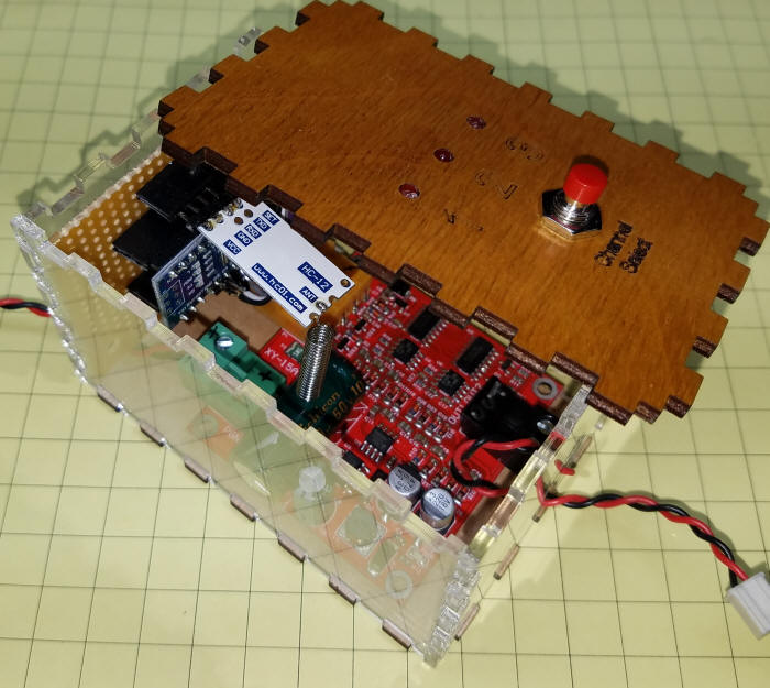
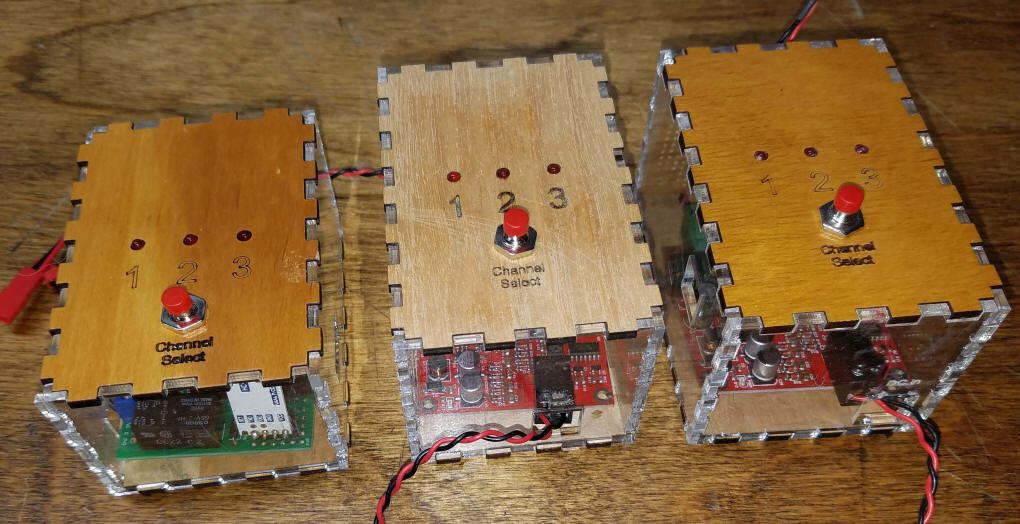
Receivers The throttle can control 1, 2 or 3 receivers. These are designed to be placed along side of and wired to the track. It is also possible to power them with batteries and place them on an engine or a trailing car. The channel that the receiver responds to is indicated by the red LED on top. To change the channel just hold the button down when you turn on the receiver - tap the button until the channel you want is lit.
|
|
|
Receiver Construction The receiver parts list and a photo are below. In addition you will need to supply 12 to24 volts DC to power your trains. I have had good service from recycled laptop power supplies.
|
|
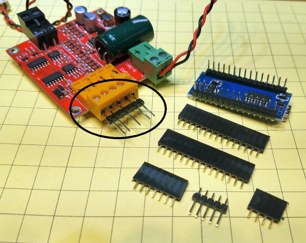
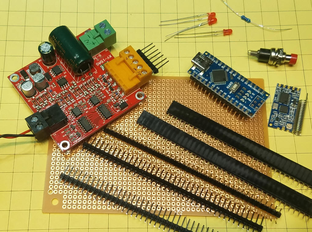 Here are the cut parts that are used with the receiver. Take special note of how the motor control board's 5 connector contacts are set up (see area circled in black). Since they are spaced wider than the 1/10" (2.54 mm) headers I cut two pins from the header and inserted them as shown. Note that this header is the one with long pins on both ends, not the ones with a shorter pin on one end. If you do not have these headers you can solder two of the shorter ones together.
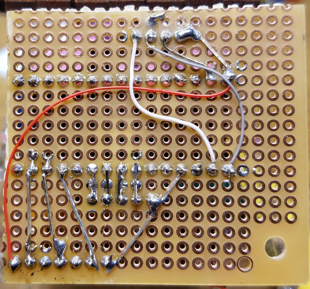
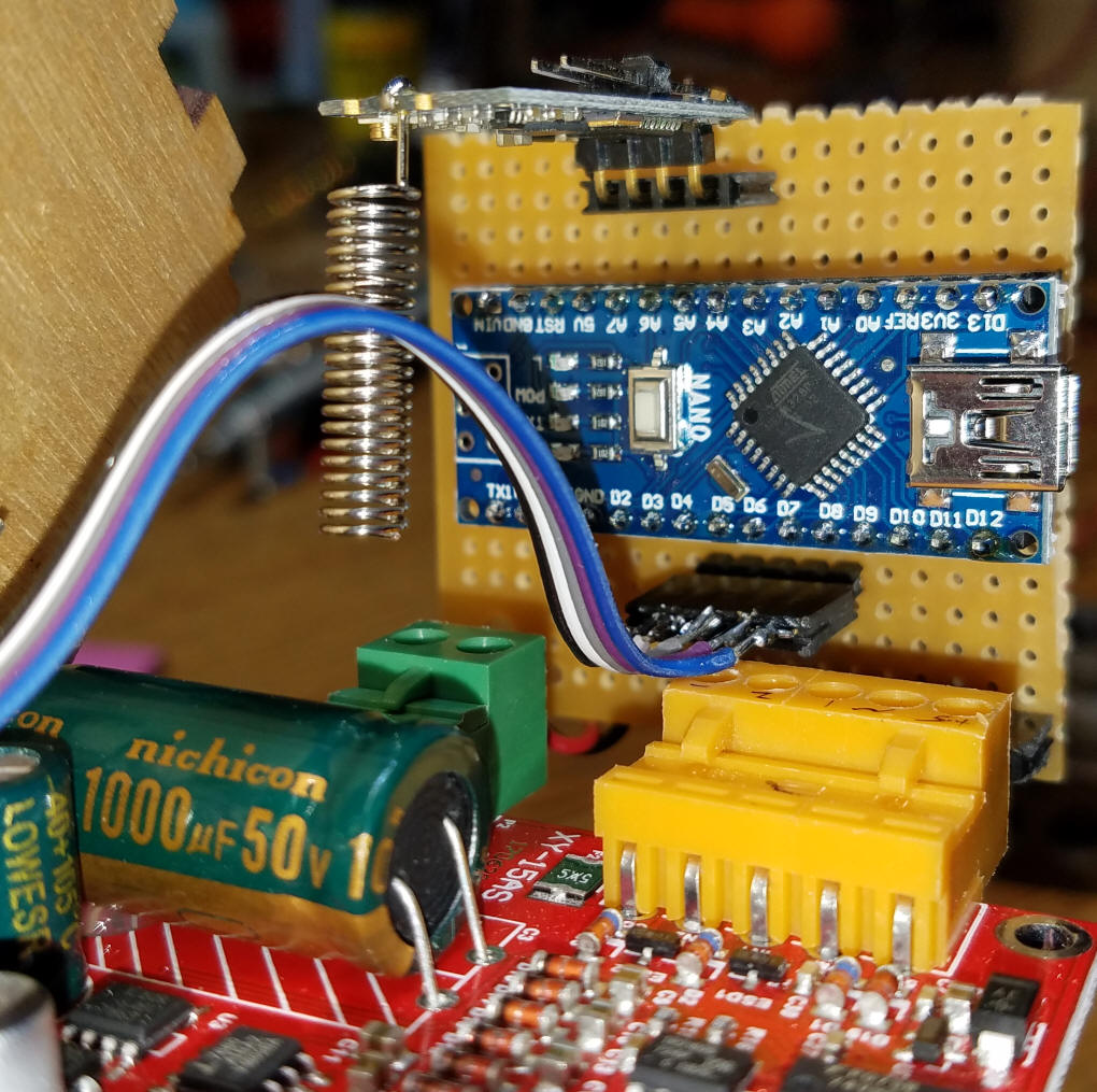
Here is a close-up of the hand wiring that was done on the back of the receiver board.
Here is a front view of the same board.
|
|
|
Receiver Schematic I opted to use a different Arduino for the receiver, the Arduino Nano, which has a USB port built into it
|
|
Receiver Code Receiver-Test-ICStationMotorBoarad-v1-6 /*
Removed Serial output to terminal as it messed up fast decel then accel
11-18-2017
Working with <t1 1111 124 0>
11-16-2017
11-16-2017 ---works with HC-12 wired from rx on Nano to tx on HC-12
TODO:
1. OK Routine to select channel - Hold button on startup then press to select channel
2.
*/
#include <SoftwareSerial.h>
int pinCount = 3;
SoftwareSerial mySerial(1, 6); // RX, TX - note, RX not used
int buusyPin = A1;// buusyPin = 10; // sound player busy
int bsy = 0;
#include<EEPROM.h>
#include <Wire.h>
int num;
const int linkButton = 7; // Link Button
int linkButtonState = 0;
const int onBoardLED = 13;
const byte numChars = 32;
char receivedChars[numChars];
int Count = 0;
boolean newData = false;
String inString = ""; // string to hold input
String saveString = "";
int TorF = 0;
// max tested was 254
#define MAX 252
int MotorSpeed = 0;
int MotorDirection = 0;
int DCCAddress = 0;
int activeAddress = 1111;
int linkAddressFlag = 0;
int DCCFunction = 0;
#define BRAKEVCC 0
#define CW 1
#define CCW 2
#define BRAKEGND 3
unsigned long time;
// 130 is about 2.5 amps
//#define CS_THRESHOLD 250 // Definition of safety current
int inApin = 10;
int inBpin = 9;
int pwmpin = 11; // PWM's input
int cspin = A0; // Current's sensor input
int i = 0;;
//int// enable = 4;
//int LED0 = 4;
//int LED1 = 5;
//int LED2 = 6;
int LED[] = { 4, 5, 6}; // an array of pin numbers to which LEDs are attached
int PushButton = 7;
void setup() {
pinMode(PushButton, INPUT_PULLUP);
mySerial.begin(9600);
delay(100);
for (int ActiveAddress = 0; ActiveAddress < pinCount; ActiveAddress++) {
pinMode(LED[ActiveAddress], OUTPUT);
}
for (int i = 0; i < 2; i++)
{
pinMode(inApin, OUTPUT);
pinMode(inBpin, OUTPUT);
pinMode(pwmpin, OUTPUT);
}
for (int i = 0; i < 2; i++)
{
digitalWrite(inApin, LOW);
digitalWrite(inBpin, LOW);
}
// pinMode(onBoardLED, OUTPUT);
pinMode(linkButton, INPUT_PULLUP);
Serial.begin(9600);
Serial.println("<Arduino is ready - version-1.3");
linkButtonState = digitalRead(PushButton);
// if button pressed on boot link to first DCC address seen
if (linkButtonState == 0) {
setAddress();
}
getAddress();
// run once with the next two lines then program without them
// activeAddress = 1111;
// DCCAddress = 1111;
setLEDs();
}
void loop() {
while (Serial.available() > 0) {
int inChar = Serial.read();
inString += (char)inChar;
if (inChar == '>') { // > is ending character
inString.trim(); // remove leading space
saveString = inString;
int bracket = inString.indexOf('<');
// Speed command seen
if (inString.substring(bracket, bracket + 3) == "<t1")
{
int nextSpace = inString.indexOf(' ');
// lop off first part of string
inString = inString.substring(nextSpace);
DCCAddress = inString.toInt();
// Serial.print(" Address = ");
// Serial.print(DCCAddress);
if (linkAddressFlag == 1) {
activeAddress = DCCAddress;
linkAddressFlag = 0;
saveAddress();
}
inString.trim(); // remove leading space
nextSpace = inString.indexOf(' ');
inString = inString.substring(nextSpace);
nextSpace = inString.indexOf(' ');
inString = inString.substring(nextSpace);
MotorSpeed = inString.toInt();
// Serial.print(" Speed = ");
// Serial.print(MotorSpeed);
inString.trim(); // remove leading space
nextSpace = inString.indexOf(' ');
inString = inString.substring(nextSpace);
MotorDirection = inString.toInt();
// Serial.print(" Fwd/Rev = ");
// Serial.println(MotorDirection);
if (DCCAddress == activeAddress) {
doMotorShield();
}
}
if (activeAddress == DCCAddress) {
}
else {
}
inString = "";
}
}
}
void doMotorShield() {
if (MotorDirection == 0) {
digitalWrite(inApin, LOW);
digitalWrite(inBpin, HIGH);
analogWrite(pwmpin, MotorSpeed );
}
else {
digitalWrite(inApin, HIGH);
digitalWrite(inBpin, LOW);
analogWrite(pwmpin, MotorSpeed );
}
}
void setAddress() {
setLEDs();
Serial.println("@@@@@ set Address");
// delay till button released
do { } while (digitalRead(PushButton) <= 0);
Serial.println("@@@@@ button released");
unsigned long temp = millis();
do {
int temp2 = digitalRead(PushButton);
if (temp2 == 0) {
do { } while (digitalRead(PushButton) <= 0);
activeAddress = activeAddress + 1111;
if (activeAddress <= 4000) Serial.println(activeAddress);
temp = millis();
if (activeAddress >= 3334) {
activeAddress = 1111;
Serial.println(activeAddress);
}
setLEDs();
delay(500);
}
} while (millis() - temp <= 3000);
DCCAddress = activeAddress;
saveAddress();
}
void setLEDs() {
digitalWrite(LED[0], LOW);
digitalWrite(LED[1], LOW);
digitalWrite(LED[2], LOW);
digitalWrite(LED[activeAddress / 1111 - 1], HIGH);
}
void saveAddress() { // TO EEPROM
int xxx = 0;
xxx = DCCAddress / 256;
EEPROM.write(0, xxx);
xxx = DCCAddress - (xxx * 256);
EEPROM.write( 1, xxx);
Serial.print("Saved Address ");
Serial.println(DCCAddress);
}
void getAddress() { // from EEPROM
int xxx = 0;
DCCAddress = EEPROM.read(0) * 256;
DCCAddress = DCCAddress + EEPROM.read( 1);
Serial.print("Read Address = ");
Serial.println(DCCAddress);
activeAddress = DCCAddress;
}
|
|
Transmitter code: Transmitter-OLED-stick--v4-0 /*
Works with Amazon units as below
1-14-2017
11-16-2017 ---works with HC-12 wired from tx on ProMini to rx on HC-12
Modification experiment to see if varying time between up/down speed
works well 12-7-2017
*/
float Ver = 4.0;
#include <SPI.h>
#include <Wire.h>
#include <Adafruit_GFX.h>
#include <Adafruit_SSD1306.h>
#define OLED_RESET 4
Adafruit_SSD1306 display(OLED_RESET);
#define NUMFLAKES 10
#define XPOS 0
#define YPOS 1
#define DELTAY 2
int LocoAddress[3] = {1111, 2222, 3333};
int LocoDirection[3] = { 1, 1, 1};
int LocoSpeed[3] = {0, 0, 0};
int ActiveAddress = 0; // make address1 active
int tempLocoSpeed = 0;
#define LOGO16_GLCD_HEIGHT 16
#define LOGO16_GLCD_WIDTH 16
static const unsigned char PROGMEM logo16_glcd_bmp[] =
{ B00000000, B11000000,
B00000001, B11000000,
B00000001, B11000000,
B00000011, B11100000,
B11110011, B11100000,
B11111110, B11111000,
B01111110, B11111111,
B00110011, B10011111,
B00011111, B11111100,
B00001101, B01110000,
B00011011, B10100000,
B00111111, B11100000,
B00111111, B11110000,
B01111100, B11110000,
B01110000, B01110000,
B00000000, B00110000
};
//#if (SSD1306_LCDHEIGHT != 64)
//#error("Height incorrect, please fix Adafruit_SSD1306.h!");
//#endif
int num;
int reverseText = 1;
// Arduino pin numbers
const int SW_pin = 2; // digital pin connected to switch output
const int X_pin = 0; // analog pin connected to X output
const int Y_pin = 1; // analog pin connected to Y output
int MapX = 0;
int MapY = 0;
int ledPins[] = { 12, 11, 10}; // an array of pin numbers to which LEDs are attached
int pinCount = 3;
//int ActiveAddress = 0;
int timer = 100;
void setup() {
Serial.begin(9600);
pinMode(SW_pin, INPUT);
for (int ActiveAddress = 0; ActiveAddress < pinCount; ActiveAddress++) {
pinMode(ledPins[ActiveAddress], OUTPUT);
}
digitalWrite(SW_pin, HIGH);
Serial.begin(9600);
// by default, we'll generate the high voltage from the 3.3v line internally! (neat!)
/// CHANGE 0x3D to 0x3C
display.begin(SSD1306_SWITCHCAPVCC, 0x3C); // initialize with the I2C addr 0x3D (for the 128x64)
// init done
display.setCursor(0, 0);
// these two lines together clear the buffer then show zip on the screen
display.clearDisplay();
display.display();
delay(100);
display.setTextColor(WHITE);
display.setCursor(0, 0);
display.println(" JoyStick Test");
display.setCursor(0, 16);
display.print("V ");
display.print(Ver);
display.print(" 11-23-17");
display.display();
delay(2000);
display.clearDisplay();
display.display();
delay(100);
digitalWrite(ledPins[ActiveAddress], HIGH);
Serial.print("Ready - version ");
Serial.println(Ver);
display.clearDisplay();
display.setTextSize(2);
display.setTextColor(WHITE);
display.setCursor(0, 0);
display.println(" Dir - Spd");
allSTOP();
}
void loop () {
display.setTextColor( WHITE, BLACK);
checkButton();
checkY(); // speed up / down
checkX(); // direction
}
void allLEDsOff() {
for (int temp = 0; temp <= 3; temp++) {
digitalWrite(ledPins[temp], LOW);
}
}
void allSTOP() {
Serial.println("@ all STOP");
int temp0 = ActiveAddress; // save address
for (int temp = 0; temp <= 2; temp++) {
ActiveAddress = temp;
LocoSpeed[temp ] = 0;
LocoDirection[temp] = 0;
doDCC();
doDCC();
doDCC();
delay(50);
}
ActiveAddress = temp0;
}
void checkButton() {
if (digitalRead(SW_pin) == 0) {
unsigned long SaveTime = millis();
while (digitalRead(SW_pin) == 0) {
// stay till button released
}
if (millis() - SaveTime <= 1000) {
// reverseText = ! reverseText;
ActiveAddress++;
if (ActiveAddress >= 3) {
ActiveAddress = 0;
}
allLEDsOff();
activeLEDon();
// digitalWrite(ledPins[ActiveAddress], HIGH);
// delay(300);
}
else {
allSTOP();
}
}
}
void activeLEDon() {
digitalWrite(ledPins[ActiveAddress], HIGH);
delay(300);
}
void checkY() { // SPEED UP / DOWN
display.setCursor(64, 18); // 10 is a bit from edge, 2nd line, 64 is mid screen
MapY = analogRead(Y_pin);
if (MapY < 520) { // down detected
MapY = map(analogRead(Y_pin), 0, 528, 0, 200);
if (LocoSpeed[ActiveAddress] >= 1) {
LocoSpeed[ActiveAddress]--;
Serial.println(MapY);
doDCC();
delay(MapY);
}
}
if (MapY > 535) { // up detected
MapY = map(analogRead(Y_pin), 528, 1023, 200, 0);
if (LocoSpeed[ActiveAddress] <= 254) {
LocoSpeed[ActiveAddress]++;
Serial.println(MapY);
doDCC();
delay(MapY);
}
}
display.print(LocoSpeed[ActiveAddress]);
display.print(" "); // clears trailing area
display.display();
}
void checkX() { // DIRECTION
display.setCursor(10, 18); // 10 is a bit from edge, 2nd line, 64 is mid screen
if (X_pin <= 528) {
MapX = map(analogRead(X_pin), 0, 528, -12, 0);
}
else {
MapX = map(analogRead(X_pin), 528, 1023, 0, 12);
}
if (MapX >= 10 && LocoDirection[ActiveAddress] == 0) {
doDecelAccel();
}
if (MapX <= -10 && LocoDirection[ActiveAddress] == 1) {
doDecelAccel();
}
if (LocoDirection[ActiveAddress] == 1) {
display.print(">>>");
}
else {
display.print("<<<");
}
display.display();
}
void doDecelAccel() {
tempLocoSpeed = LocoSpeed[ActiveAddress];
for (LocoSpeed[ActiveAddress] = tempLocoSpeed; LocoSpeed[ActiveAddress] >= 0; LocoSpeed[ActiveAddress] = LocoSpeed[ActiveAddress] - 10) {
if (LocoSpeed[ActiveAddress] < 0) LocoSpeed[ActiveAddress] = 0;
doDCC();
allLEDsOff();
digitalWrite(ledPins[0], HIGH);
digitalWrite(ledPins[1], HIGH);
digitalWrite(ledPins[2], HIGH);
delay(5 );
digitalWrite(ledPins[0], LOW);
digitalWrite(ledPins[1], LOW);
digitalWrite(ledPins[2], LOW);
delay(5);
}
Serial.println("Done decel");
delay(400);
LocoDirection[ActiveAddress] = ! LocoDirection[ActiveAddress];
for (LocoSpeed[ActiveAddress] = 0; LocoSpeed[ActiveAddress] <= tempLocoSpeed; LocoSpeed[ActiveAddress] = LocoSpeed[ActiveAddress] + 10) {
if (LocoSpeed[ActiveAddress] < 0) LocoSpeed[ActiveAddress] = 0;
doDCC();
allLEDsOff();
digitalWrite(ledPins[0], HIGH);
digitalWrite(ledPins[1], HIGH);
digitalWrite(ledPins[2], HIGH);
delay(5 );
digitalWrite(ledPins[0], LOW);
digitalWrite(ledPins[1], LOW);
digitalWrite(ledPins[2], LOW);
delay(5);
}
LocoSpeed[ActiveAddress] = tempLocoSpeed ;
allLEDsOff();
activeLEDon();
}
void doDCC() {
Serial.print("<t1 ");
Serial.print(LocoAddress[ActiveAddress] );//locoID);
Serial.print(" ");
Serial.print(LocoSpeed[ActiveAddress] );
Serial.print(" ");
Serial.print(LocoDirection[ActiveAddress] );
Serial.write(">");
Serial.println("");
}
|
|