Arduino DCC Function Decoder
Operating 8 Relays
Revised 10-08-14
A video is on YouTube here:
http://youtu.be/fERIjH9iPzE
|
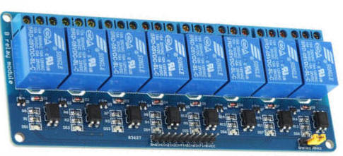
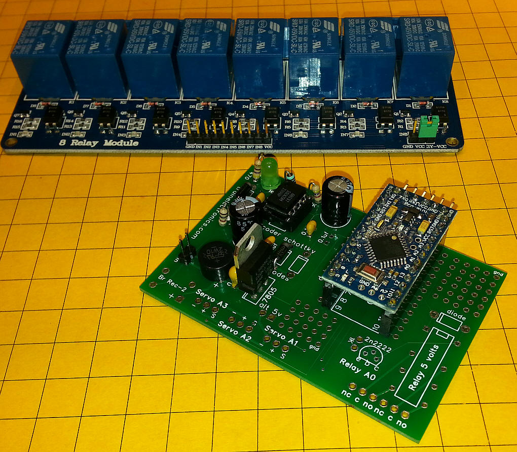
Introduction 5V 8 Channel Relay Module -- they typically sell for about $10.00
Similar modules that control 1, 2 or 4 relays are also available. The objective of this exercise is to physically connect the relay board to the Arduino DCC board and to revise the software to operate it from the function keys on a DCC throttle. |
|
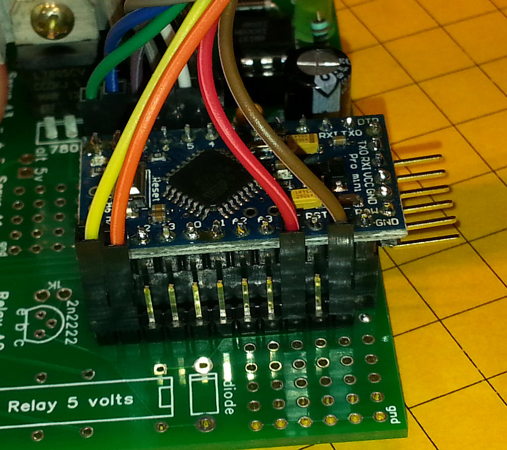
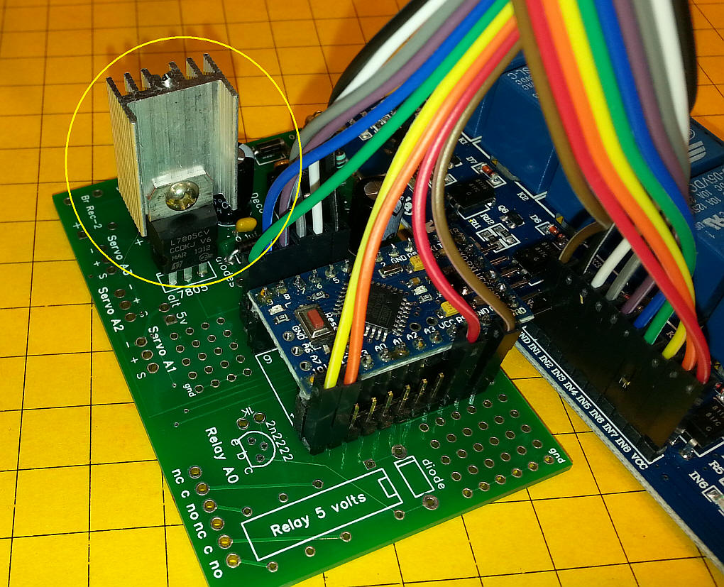
Hardware Setup The circuit board does not need to be fully populated for this application. The DPDT relay and the transistor that operates it can be skipped along with the 3 servo headers. To simplify connection to the relay board a set of pins was added to the holes along side the Arduino's pins. The first photo shows the pins that are used for +5 volts, ground and Arduino pins 10 and 11.
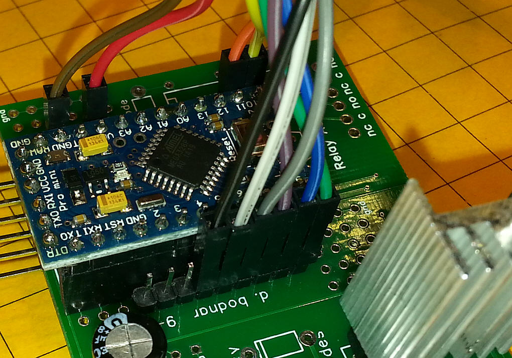
The other side connects to Arduino pins 4 through 9.
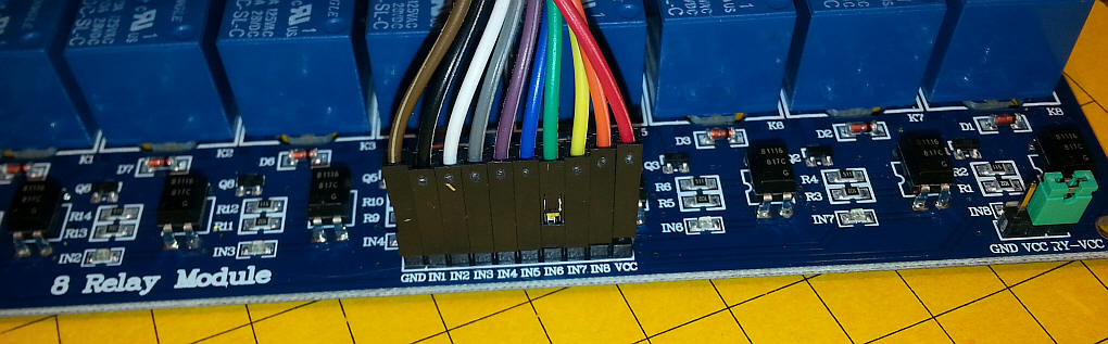
The connections to the 8 relay module are shown here:
|
|
Heat Sink or Supplementary 5 Volt Power A heat sink was added to the 7805 voltage regulator as the drop from DCC voltage to 5 volts requires the dissipation of quite a bit of energy. Even with the heat sink the regulator can easily reach a temperature of 200 degrees F when all 8 relays are closed. If you have an alternative source of 5 volts it can be connected to the VCC input on the 8 relay module. Make sure that the ground from that power source goes to both the relay module and the Arduino board.
|
|
Software The program for the Arduino is identical to the one on Geoff Bunza's blog with a few minor exceptions. As Geoff's program operates each of the pins that operates an LED is held low. When a function key on the DCC throttle is activated the LED pin goes high and the LED lights. Unfortunately this is the opposite of what happens with the Relay Module. Each of the relays is activated when the corresponding pin is pulled low. This means that when Geoff's program initializes all 8 of the relays are latched and pressing a function key unlatches it. This means that the current being pulled by the relay module is at its maximum (with the most heat being generated in the 7805) when all functions are "off". To reverse this situation I added an exclamation mark ("!") before the code that activated the LEDs. I have highlighted these lines in the code below. #include <NmraDcc.h> //MAKE SURE YOU USED GEOFF's VERSION OF THIS LIBRARY!
#include <SoftwareSerial.h>
//for serial port on USB
byte rxPin = 0;
byte txPin = 1;
SoftwareSerial mySerial = SoftwareSerial(rxPin, txPin);
// Working 14 Function DCC Decoder DccAckPin not needed
int tim_delay = 500;
#define numleds 17
byte ledpins [] = {
0,3,4,5,6,7,8,9,10,11,12,13,14,15,16,17,18,19};
const int FunctionPin0 = 3;
const int FunctionPin1 = 4;
const int FunctionPin2 = 5;
const int FunctionPin3 = 6;
const int FunctionPin4 = 7;
const int FunctionPin5 = 8;
const int FunctionPin6 = 9;
const int FunctionPin7 = 10;
const int FunctionPin8 = 11;
const int FunctionPin9 = 12;
const int FunctionPin10 = 13;
const int FunctionPin11 = 14; //A0
const int FunctionPin12 = 15; //A1
const int FunctionPin13 = 16; //A2
const int FunctionPin14 = 17; //A3
const int FunctionPin15 = 18; //A4
const int FunctionPin16 = 19; //A5
NmraDcc Dcc ;
DCC_MSG Packet ;
#define This_Decoder_Address 17
extern uint8_t Decoder_Address = This_Decoder_Address;
struct CVPair
{
uint16_t CV;
uint8_t Value;
};
CVPair FactoryDefaultCVs [] =
{
{
CV_MULTIFUNCTION_PRIMARY_ADDRESS, This_Decoder_Address }
,
{
CV_ACCESSORY_DECODER_ADDRESS_MSB, 0 }
,
{
CV_MULTIFUNCTION_EXTENDED_ADDRESS_MSB, 0 }
,
{
CV_MULTIFUNCTION_EXTENDED_ADDRESS_LSB, 0 }
,
};
uint8_t FactoryDefaultCVIndex = 0;
void notifyCVResetFactoryDefault()
{
// Make FactoryDefaultCVIndex non-zero and equal to num CV's to be reset
// to flag to the loop() function that a reset to Factory Defaults needs to be done
FactoryDefaultCVIndex = sizeof(FactoryDefaultCVs)/sizeof(CVPair);
};
void setup()
{
pinMode(rxPin, INPUT);
pinMode(txPin, OUTPUT);
mySerial.begin(9600);
// initialize the digital pins as an outputs
for (int i=1; i<= numleds; i++) {
pinMode(ledpins[i], OUTPUT);
digitalWrite(ledpins[i], LOW);
}
for (int i=1; i<= numleds; i++) {
digitalWrite(ledpins[i], HIGH);
delay (tim_delay/10);
}
delay( tim_delay);
for (int i=1; i<= numleds; i++) {
digitalWrite(ledpins[i], LOW);
delay (tim_delay/10);
}
delay( tim_delay);
// Setup which External Interrupt, the Pin it's associated with that we're using and enable the Pull-Up
Dcc.pin(0, 2, 0);
// Call the main DCC Init function to enable the DCC Receiver
Dcc.init( MAN_ID_DIY, 100, FLAGS_MY_ADDRESS_ONLY, 0 );
}
void loop()
{
// You MUST call the NmraDcc.process() method frequently from the Arduino loop() function for correct library operation
Dcc.process();
if( FactoryDefaultCVIndex && Dcc.isSetCVReady())
{
FactoryDefaultCVIndex--; // Decrement first as initially it is the size of the array
Dcc.setCV( FactoryDefaultCVs[FactoryDefaultCVIndex].CV, FactoryDefaultCVs[FactoryDefaultCVIndex].Value);
}
}
extern void notifyDccFunc( uint16_t Addr, uint8_t FuncNum, uint8_t FuncState) {
if (FuncNum==1) { //Function Group 1 F0 F4 F3 F2 F1
digitalWrite( FunctionPin0, !(((FuncState&0x10)>>4)));
digitalWrite( FunctionPin1, !((FuncState&0x01 ))); // physical pin 4
digitalWrite( FunctionPin2, !((FuncState&0x02)>>1 )); // physical pin 5
digitalWrite( FunctionPin3, !((FuncState&0x04)>>2 )); // physical pin 6
digitalWrite( FunctionPin4, !((FuncState&0x08)>>3 )); // physical pin 7
mySerial.println(FuncState, BIN);
}
else if (FuncNum==2) { //Function Group 1 S FFFF == 1 F8 F7 F6 F5 & == 0 F12 F11 F10 F9 F8
if ((FuncState & 0x10)==0x10) {
digitalWrite( FunctionPin5, !((FuncState&0x01 ))); // physical pin 8
digitalWrite( FunctionPin6, !((FuncState&0x02)>>1 )); // physical pin 9
digitalWrite( FunctionPin7, !((FuncState&0x04)>>2 )); // physical pin 10
digitalWrite( FunctionPin8, !((FuncState&0x08)>>3 )); // physical pin 11
}
else {
digitalWrite( FunctionPin9, !((FuncState&0x01 )));
digitalWrite( FunctionPin10, (FuncState&0x02)>>1 );
digitalWrite( FunctionPin11, (FuncState&0x04)>>2 );
digitalWrite( FunctionPin12, (FuncState&0x08)>>3 );
}
}
else if (FuncNum==3) { //Function Group 2 FuncState == F20-F13 Function Control
digitalWrite( FunctionPin13, (FuncState&0x01 ));
digitalWrite( FunctionPin14, (FuncState&0x02)>>1 );
digitalWrite( FunctionPin15, (FuncState&0x04)>>2 );
digitalWrite( FunctionPin16, (FuncState&0x08)>>3 );
}
}
|