| Introduction I am a member of the South Hills Model Railroad club in Pittsburgh and our most recent project has been to build an HO modular layout. We decided to control the trains with DCC and I wanted to have a DCC system at home to test my trains and module. My first DCC system was the MiniDCC system that is described in some detail on my web page (see: http://www.trainelectronics.com/miniDCC/index.htm ) and on the MiniDCC web page (see: http://www.minidcc.com/ ). The MiniDCC system works well but it is not compatible with computer operation using JMRI. I had some experience with JMRI and our club's Digitrax system and wanted to be able to operate that at home with my own equipment. The simplest route would have been to purchase a Digitrax system for home but I opted to get a less expensive unit, the SPROG II, which was designed to work with JMRI. The SPROG II unit did everything that I needed with one limitation. It could only deliver about one amp of power to the track. This was fine for programming and running one locomotive at a time but I wanted the ability to deliver more power and run more trains. I decided to take the 3 amp booster portion of the MiniDCC system and use it to deliver more power from the SPROG II. What follows is the end result of that project. The finished unit more than met my expectations and it may fit into your DCC plans as well. Objectives The primary objective of this project is to design and build a 3 amp DCC booster that can be used as an add-on to any DCC system, not just the SPROG II. In addition the completed unit will have three LEDs that will display the amount of current that the system is supplying. When this current is in excess of 3.3 amps the power will be shut off and the unit will be in a non-powered stand-by mode until the reset button is pressed. To simplify the connection to an existing DCC system a jumper from the DCC track output is all that is needed to pass the DCC data signal to the booster. It is not necessary to go inside of an existing DCC system to find the 5 volt peak-to-peak DCC signal before it is sent to the track. An optoisolator completely isolates the DCC booster from the primary DCC system.
|
|
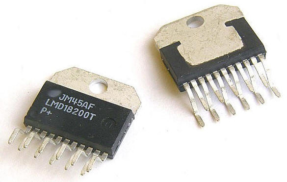
Hardware The main component in any DCC power system is an H-Bridge. You can think of an H-Bridge as being a solid state double pole double throw switch that can also be used to vary the amount of power that passes through it. For this booster a 3 amp H-Bridge, part number LMD18200, was chosen. This is a fairly inexpensive part that can be used as a DCC booster with just a few additional parts.
A microcontroller, a PIC 16F684, is used to drive the LED power display and to shut down the LMD18200 should it exceed its rated power capacity. A fan cooled heat sink is used to assure that the H-Bridge stays cool. The fan and heat sink are especially important if the chip is used near its design limits. |
| Schematic <ADD POLYFUSE or FUSE>
|
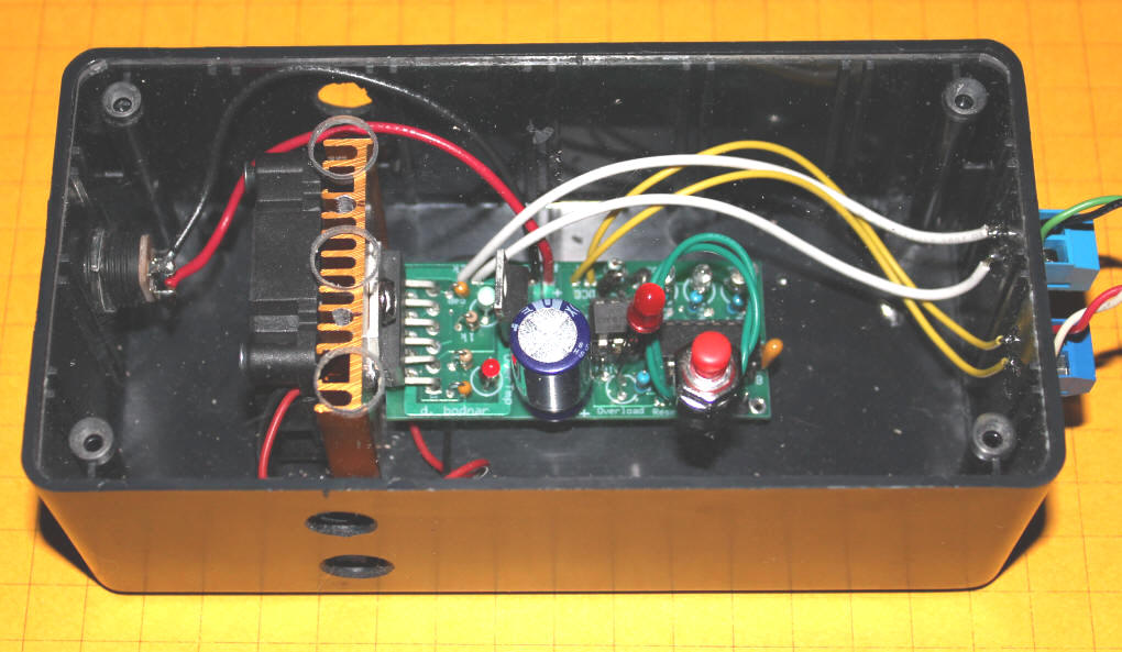
| A circuit board was designed and sent off for fabrication to
simplify construction of the booster. In this photo of the
finished unit you can see the LMD18200 all the way to the left of
the circuit board. It is screwed to the gold colored heat
sink. The PIC 16F684 is to the right and the 4N27 optoisolator
is to the PIC's left. The three LEDs that show the current
being supplied by the booster are just above the 16F684.
The larger red LED flashes when the system goes into stand-by after
detecting excessive current. You can also see the holes that have been drilled in the black project box and the clear cover that allow the fan to circulate air through the enclosure.
|
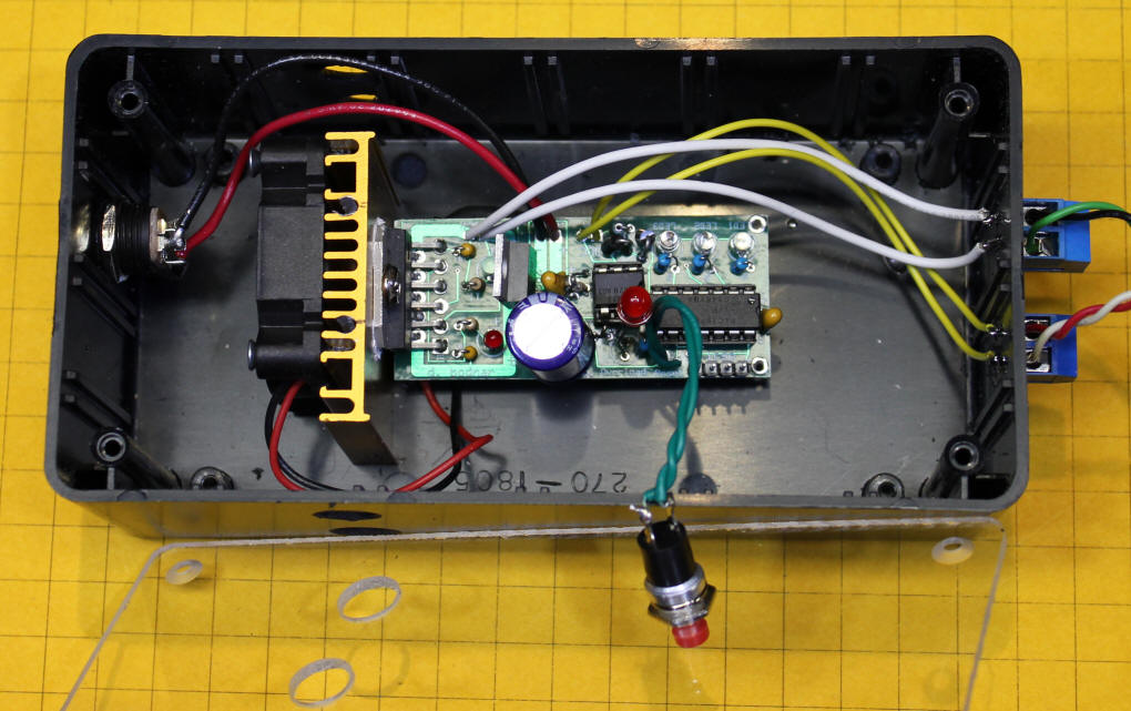
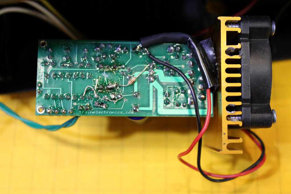
| This photo shows the bottom of the circuit board. Note
that a small amount of rework was required (center of the board) as
the optoisolator circuit was redesigned to optimize the system after
the boards were made. The next revision of the circuit board
will not need to have these modifications. The black and red
wires to the right connect to the fan on the heat sink. The
fan runs continuously when power is applied to the booster.
|
| Software and Operation To use the booster connect the DCC In contacts to the DCC output of the main DCC system. The DCC output connection goes to the track. Power is provided by a 15 volt power supply from a retired laptop computer. Any source of reasonably clean DC power will work. It is important to remember that this booster is NOT designed to work with AC power as are many DCC boosters. When the booster is not supplying power to a train all three of the power LEDs are off. Once the unit is supplying more than 0.5 amps but less than 1.0 amp the first LED will flash on and off. When the power gets to at least 1.0 amp but less than 1.5 amps the first LED stops flashing and remains on. Following the same pattern the second LED begins to flash at 1.5 amps and is solidly lit at 2.0 amps. The third LED flashes at 2.5 amps and is solid at 3.0 amps. When the power exceeds 3.0 amps all three LEDs flash. When it exceeds 3.5 amps the power is shut off and the 4th LED, a flashing red 5mm LED, is turned on. At this point the system remains in stand-by mode until the reset button is pressed or until the power is turned off and back on. Please note that the current display indications described above are not meant to be a precise representation of how much power the LMD18200 is supplying. They are good approximations based on testing with an amp meter in series with the H-Bridge output. The software is written in PIC Basic Pro. The routines are well documented and should be easy to follow. |
|
Conclusion I have used the booster for many hours at and above 2 amps and have had no problems with it or the operation of the DCC trains. The power delivered to a layout could easily be increased by setting up blocks and powering each of them with separate boosters. This has turned out to be a very satisfying project and a cost-effective way to extend my DCC system.
|