|
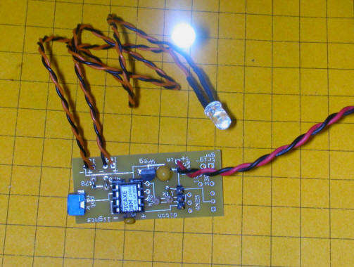
| The photo above shows a close-up of the wired board. The
two wires coming off to the right are the power leads. They
connect to a source of 7-24 volts DC. The unit will begin to
operate at 4 volts but the full brightness of the LEDs will not be
reached until 7 volts or more is applied. The red wire MUST
connect to the positive terminal of the power source and the black
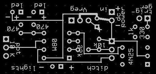
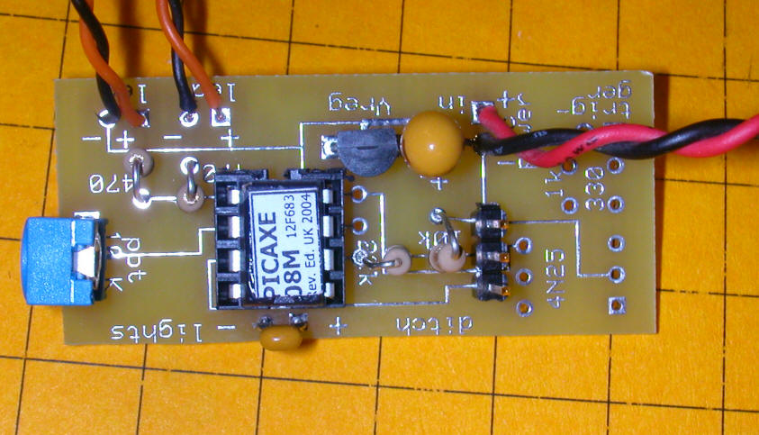
to the negative. The two LEDs are attached to the orange / black wires coming out of the top of the board. Note the "+" and "-" markings where the wires are soldered to the board. The rate of flashing can be adjusted by inserting a small Phillips head screwdriver in the blue potentiometer that is in the lower left corner of the circuit board. The three pin header in the lower right is for programming the Picaxe. The photo below is just a wider shot of the same board. There are a number of positions on the board for components that are not used in this configuration.
|
| rem d.bodnar 4-25-06 rev1 rem ditch light symbol led = 2 symbol temp = w0 'for/next variable symbol temp2 = w3 symbol RatePin = 1 symbol Rate = b8 'top:readadc RatePin, temp2:debug temp2:goto top: again: for temp=0 to 1023 step 30 readadc ratepin, rate 'if rate > 100 then allon: pwmout led, 255, temp',550'temp2 'debug temp pause rate next temp for temp=1023 to 0 step -30 readadc ratepin , rate pwmout led, 255, temp ', 550'temp2 'debug temp pause rate next temp goto again: allon: low 0 high 4 goto again: |