Using an Arduino Uno to Program
an ATTiny85
revised 11-23-2020 d. bodnar
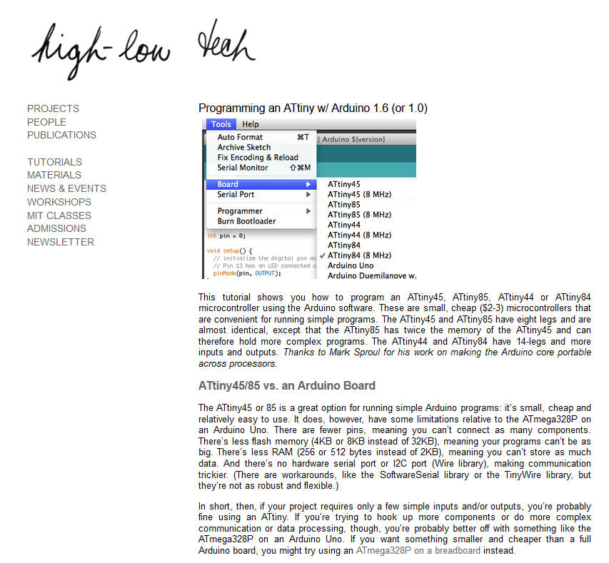
| This page describes one way to program the
ATTiny family of microcontrollers. Here it is used to program
the ATTiny85. The actual programming is done by turning an
Arduino Uno into a programmer and wiring pins on the ATTiny to the
Uno. There are a number of ways to do
this that described on the Internet. The one I used is
excellent and I encourage you to follow the steps there and do a
test program as suggested.
http://highlowtech.org/?p=1695
Here is a link to another method -
https://www.instructables.com/How-to-Program-an-Attiny85-From-an-Arduino-Uno/
|
Programming Connections
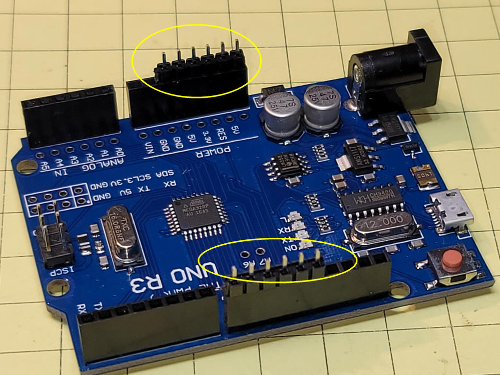
These images show how I built a programming interface that fits
to the Arduino UNO.First add 2 six
pin headers to the board as shown. Note the placement!
The "POWER" header skips the VIN and GND pins and the other goes to
pins 8 through 13.
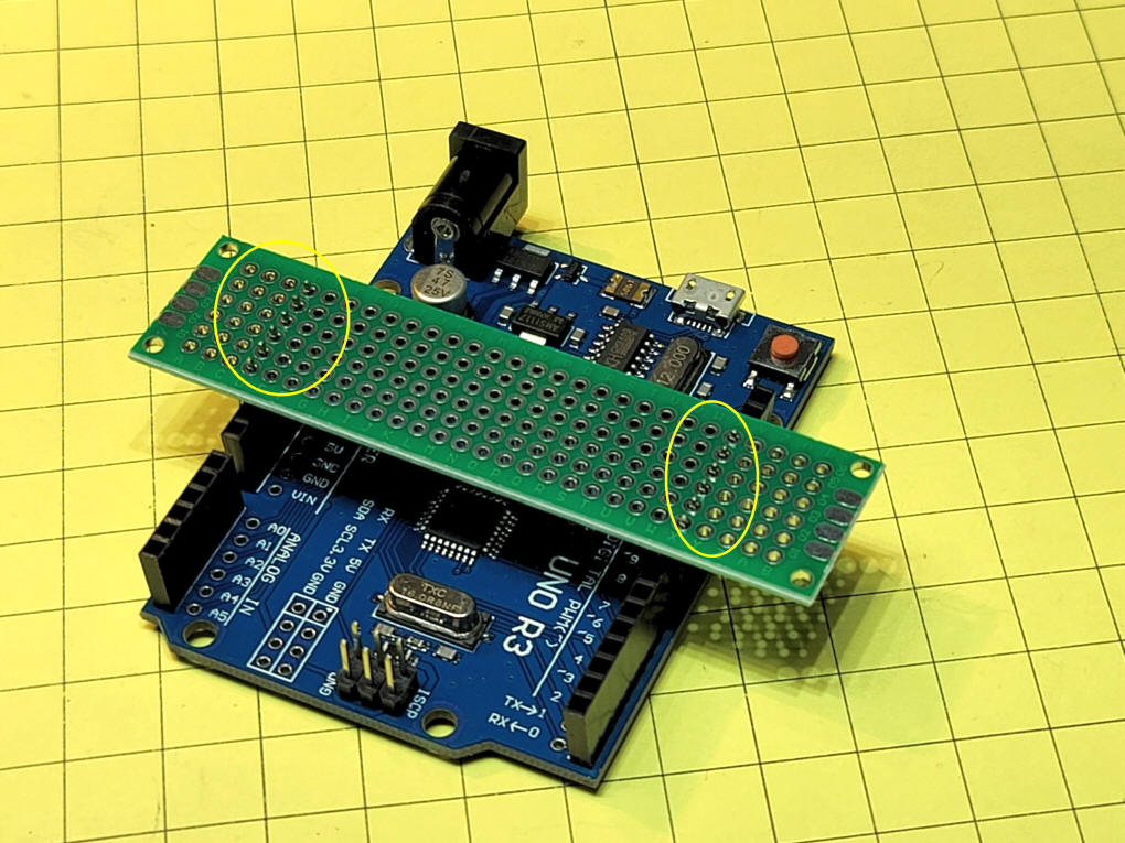
Place a small prototype board (mine
is from Amazon) to the pins.
Note that the two sides do not line up perfectly from one side to
the other and you may need to force the pins into the holes.
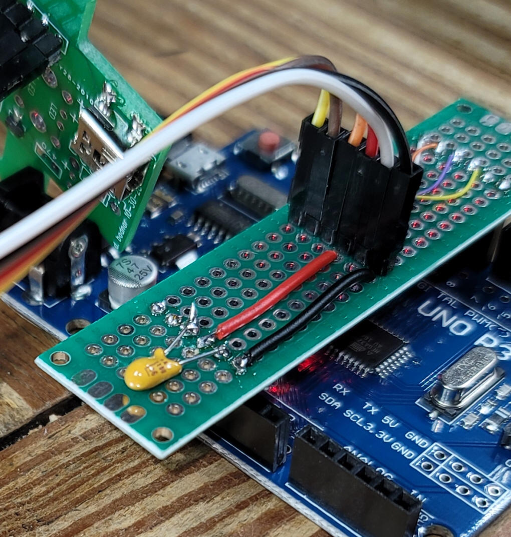
Solder the pins to the boards and add
another six pin header to the center of the board.
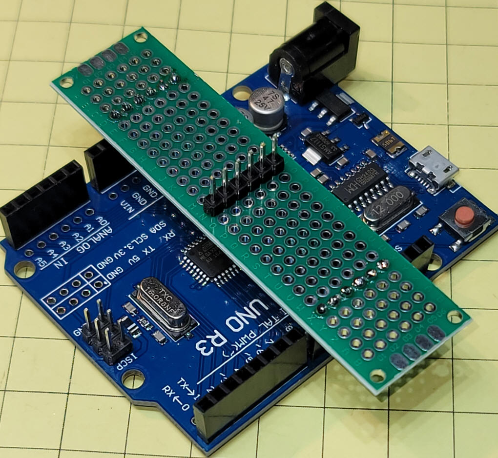
Wires to +5 volts and ground go to the left
side of the board. You also need to add a 10uf capacitor to
the reset and ground pins (+ on the capacitor goes to reset and the
negative goes to ground). If you look carefully you will see
that the wires to the center header go into the hole before the pin
so that they can be soldered on the bottom
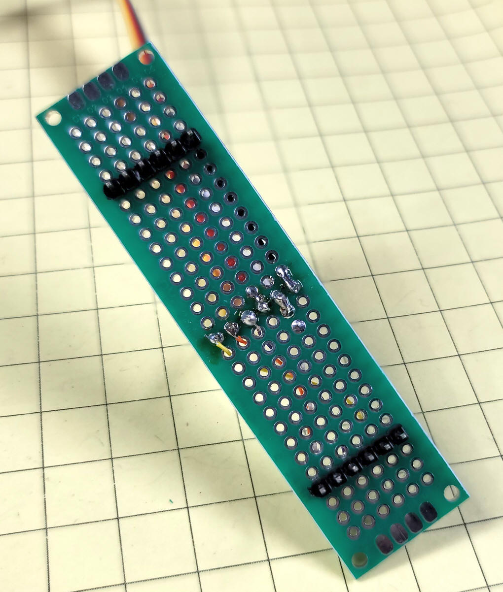
Here you see the bottom of the board.
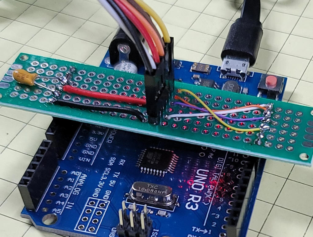
The completed board with four connections
on the right that go to pins 10, 11, 12 and 13
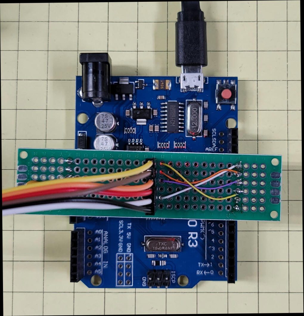
This overhead photo clearly shows that the
add-on board is not square with the Arduino.
The above photo shows the order of the
connections. Starting at the bottom of the center header
- the black wire goes to ground.
- the white wire goes to pin 13
- the red wire goes to VCC (+5 volts)
- the orange wire goes to pin 11
- the brown wire gores to pin 12
- the yellow wore goes to pin 10
|
Tiny AVR Programmer
There is also a programmer that includes all of the above as a
stand-alone programmer. It is called the Tiny AVR Programmer
and is available from
Amazon and
other sources.Details about
setting it up and using it are here:
http://highlowtech.org/?p=1801 |
| |
| |
/*  Translation of Drone Beacon from PIC to Arduino
     d. bodnar  11-12-2020
*/
#include <avr/sleep.h>
#include <avr/interrupt.h>
#include <SoftwareSerial.h>
#define RX    3   // *** D3, Pin 2
#define TX    4   // *** D4, Pin 3
int LED = 0;
int dozeCounter = 0;  // hold button for 5 repeats goes to sleep
const int buttonPin = 3;     // the number of the pushbutton pin (physical pin 2)
const int ledPin =  0;      // the number of the LED pin (physical pin 5)
int buttonState = 0;         // variable for reading the pushbutton status
// NOTE: you have to capture serial output via serial converter on pin 3 on ATTINY -
//    used TeraTerm @ 9600
SoftwareSerial Serial(RX, TX);
int counter = 1;
void setup()
{
  Serial.begin(9600);
  pinMode(LED, OUTPUT);
  pinMode(buttonPin, INPUT_PULLUP);
  Serial.println("Drone Beacon on ATTiny85--Ver 3.6.");
}
void loop()
{
  dozeCounter = 0;
  Serial.print (" @ LOOP  "); Serial.print(counter); Serial.print(" Button "); Serial.println(buttonState);
  checkButton();
  switch (counter) {
    case 1:
      fullBrightSlow();
      break;
    case 2:
      fullBrightFast();
      break;
    case 3:
      fivePause();
      break;
    case 4:
      threeTen();
      break;
    case 5:
      another();
      break;
  }
}
// 1 1 1
void fivePause() {
  digitalWrite(LED, HIGH);
  for (int i = 1; i <= 5; i++) {
    checkButton();
    digitalWrite(LED, LOW);
    delay(25);
    digitalWrite(LED, HIGH);
    delay(25);
  }
  checkButton();
  delay(250);
}
// 2 2 2
void fullBrightFast() {
  digitalWrite(LED, LOW);
  delay(60);
  checkButton();
  digitalWrite(LED, HIGH);
  delay(60);
}
// 3 3 3
void fullBrightSlow() {
  digitalWrite(LED, LOW);
  checkButton();
  delay(500);
  checkButton();
  digitalWrite(LED, HIGH);
  checkButton();
  delay(500);
  checkButton();
}
// 4 4 4
void threeTen() {
  for (int xx = 1; xx <= 3; xx++) {
    checkButton();
    for (int i = 1; i <= 10; i++) {
      checkButton();
      digitalWrite(LED, LOW);
      delay(10);
      digitalWrite(LED, HIGH);
      delay(10);
    }
    checkButton();
    delay(50);
  }
  for (int i = 1; i <= 10; i++) {
    checkButton();
    digitalWrite(LED, LOW);
    delay(30);
    digitalWrite(LED, HIGH);
    delay(30);
    checkButton();
  }
  delay (250);
}
//5 5 5
void another() {
  digitalWrite(LED, LOW);
  delay(100);
  checkButton();
  digitalWrite(LED, HIGH);
  delay(25);
}
void checkButton() {
  buttonState = digitalRead(buttonPin);
  if (buttonState == HIGH) {
  } else {
    counter = counter + 1;
    if (counter == 6) {
      counter = 1;
    }
  }
  while (digitalRead(buttonPin) == LOW) { // debounce button
    for (int i = 1; i <= counter; i++) {
      digitalWrite(LED, HIGH);
      delay(100);
      digitalWrite(LED, LOW);
      delay (100);
    }
    dozeCounter = dozeCounter + 1;
    Serial.print("dozeCounter ");  Serial.println(dozeCounter);
    if (dozeCounter >= 5) {
      Serial.println(" @ 5 count");
      for (int xx = 255; xx >= 1; xx = xx - 2) {
        analogWrite(LED, xx);
        delay(10);
      }
      delay(1000);
      sleep();
    }
    delay(500);
  }
}
void sleep() {
  counter = counter - 1;
  if (counter == 0) {
    counter = 5;
  }
  Serial.print(counter); Serial.println(" SLEEPING ");
  GIMSK |= _BV(PCIE);                     // Enable Pin Change Interrupts
  PCMSK |= _BV(PCINT3);                   // Use PB3 as interrupt pin
  ADCSRA &= ~_BV(ADEN);                   // ADC off
  set_sleep_mode(SLEEP_MODE_PWR_DOWN);    // replaces above statement
  sleep_enable();                         // Sets the Sleep Enable bit in the MCUCR Register (SE BIT)
  sei();                                  // Enable interrupts
  sleep_cpu();                            // sleep
  cli();                                  // Disable interrupts
  PCMSK &= ~_BV(PCINT3);                  // Turn off PB3 as interrupt pin
  sleep_disable();                        // Clear SE bit
  ADCSRA |= _BV(ADEN);                    // ADC on
  sei();                                  // Enable interrupts
  Serial.print(counter); Serial.println(" DONE SLEEPING!!!");
  for (int xx = 1; xx <= 255; xx = xx + 2) {
    analogWrite(LED, xx);
    delay(10);
  }
} // sleep