|
1
|
|
|
2
|
|
|
3
|
|
|
4
|
- Using my electronics skills to enhance what can be done with a model
railroad
- Building unique & custom circuits for model railroads
- Making presentations & writing articles about how to “roll
your own” circuits to satisfy my need to teach!
|
|
5
|
- Show how microcontrollers are programmed and connected to interact with
railroad equipment
- (Hopefully) Excite you with the possibilities and enable you to begin
experimenting!
|
|
6
|
- Designed in the UK for use in schools
- SUPERB support
- Free manuals, tutorials and software
- Active & helpful forums on their web page & elsewhere on the web
- PICAXE manuals, especially “section 3- Interfacing Circuits”
are super in helping to put it all together on your railroad
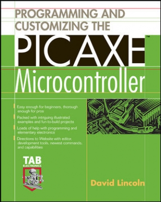
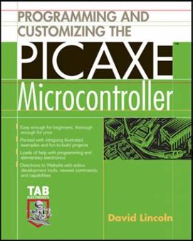
- Book: “Programming
& Customizing the PICAXE Microcontroller”
|
|
7
|
- Best choice in terms of:
- Capability
- Ease of use
- Cost
- Support
- dave@davebodnar.com
- Many PICAXE articles at Large Scale Online &
- www.trainelectronics.com
|
|
8
|
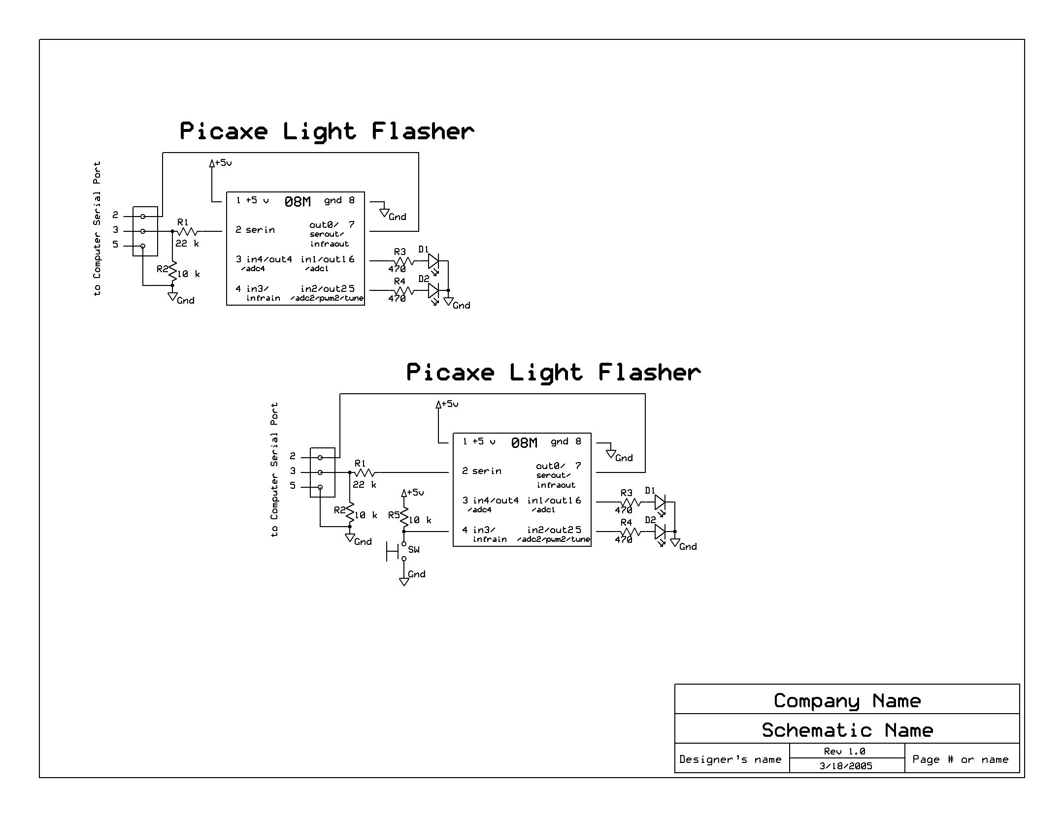
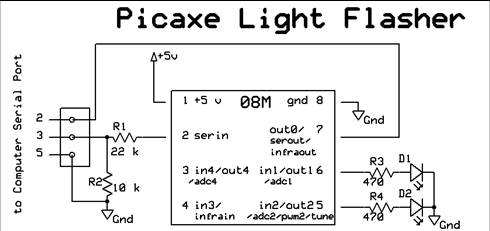
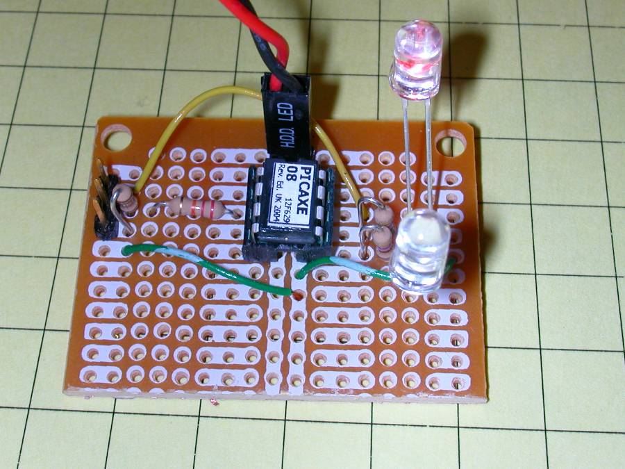
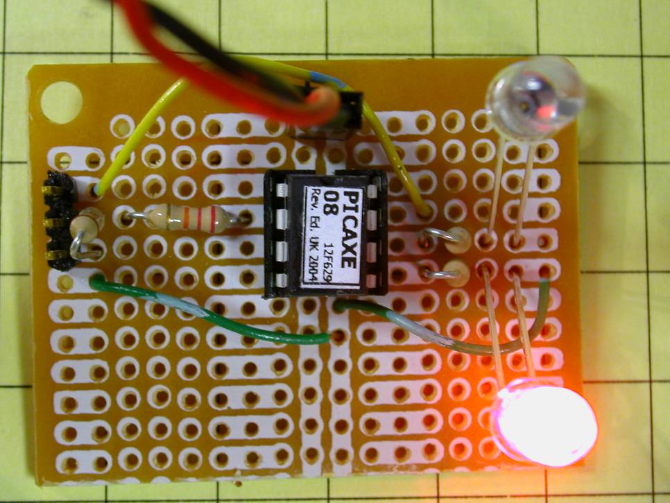
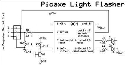
- Design objectives:
- Alternately flash two red LEDs
- Operate from battery power
- Alter timing and other characteristics from software
|
|
9
|
- Then we will modify the circuit to:
- Start from a button push
- Do other “flashing” things by making minor changes in
hardware & software
|
|
10
|
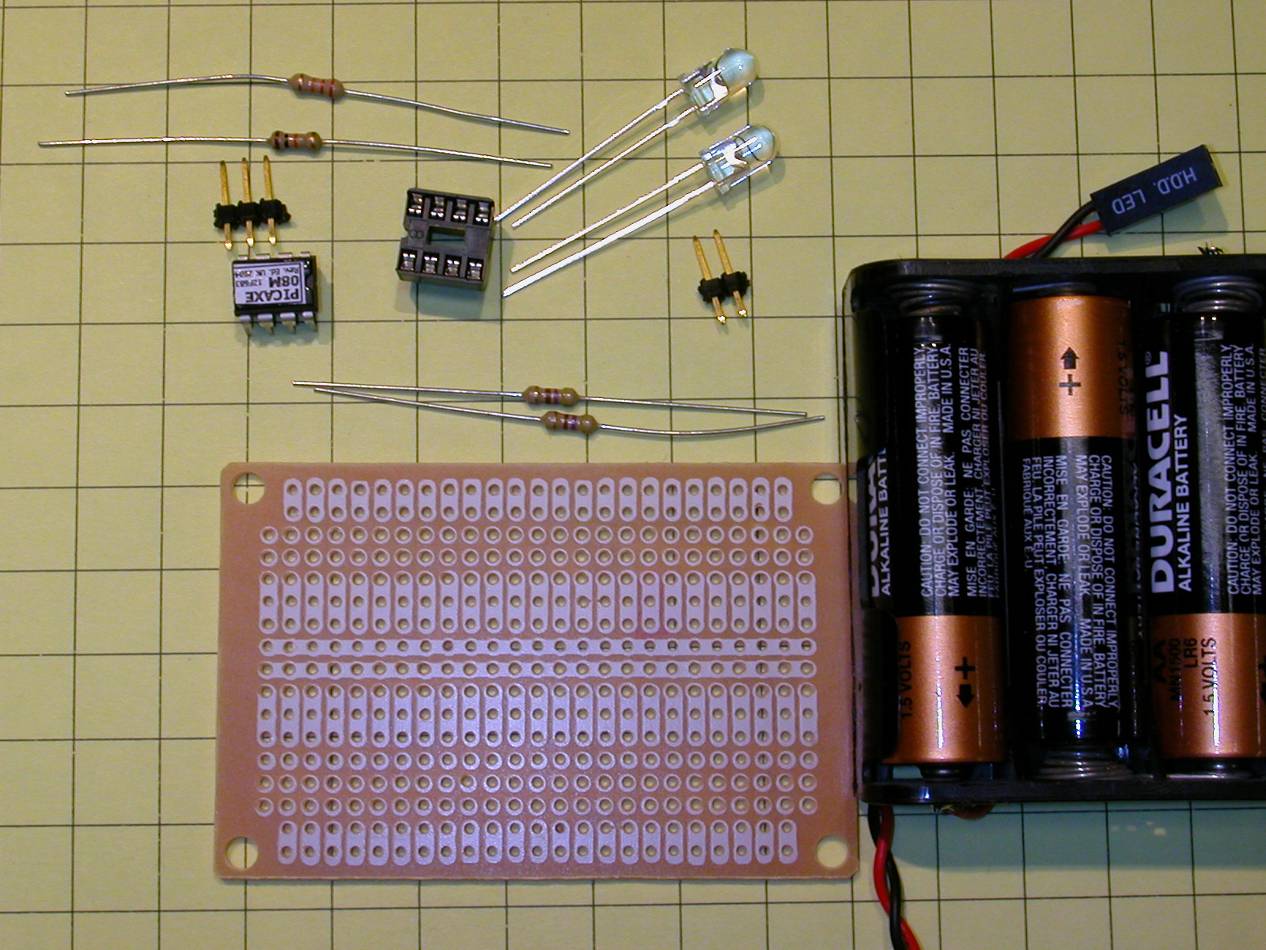
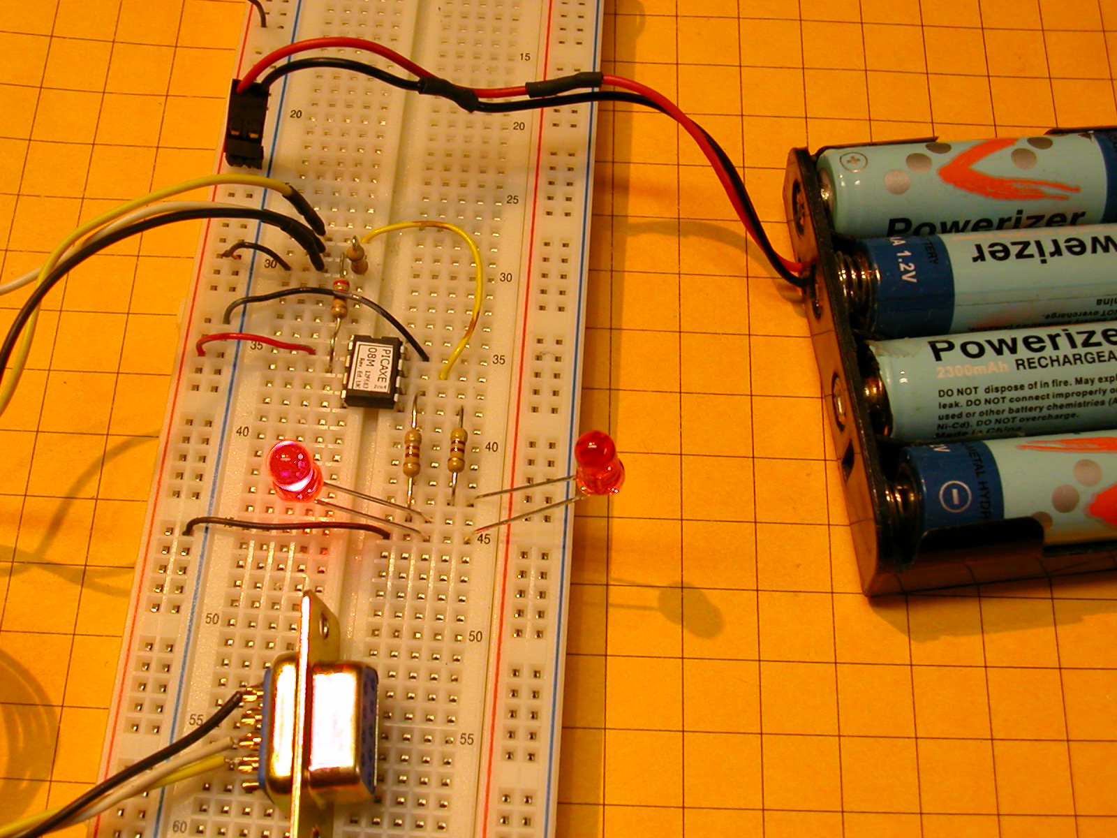
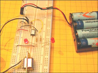
- Parts:
- Cost:
- Less than
- $10.00
|
|
11
|
- Software: free from www.picaxe.com
|
|
12
|
- Other items needed:
- Any Windows PC with serial port (or USB to serial adapter)
- Programming cable
- Needs only 3 wires - can use an old mouse cable
- http://www.allelectronics.com/cgi-bin/item/CON-243/search/3-PIN_CONNECTOR_W_HEADER,_.1%22#34;_.html
- http://www.allelectronics.com/cgi-bin/item/DB-9S/search/D-SUB_CONNECTOR,_9_PIN_FEMALE_.html
- Soldering iron & wire cutters, etc.
- A Solderless Development Package is available from www.phanderson.com
for < $20.00
- 4.5 to 5.5 volt power supply (3 @ AA cells)
- Can operate with as little as 2 volts
- Higher voltage needed for programming
|
|
13
|
|
|
14
|
|
|
15
|
|
|
16
|
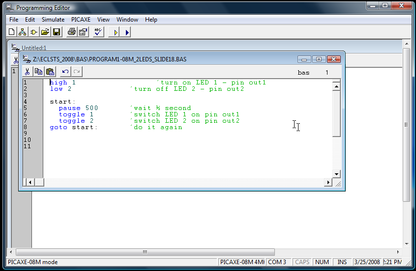
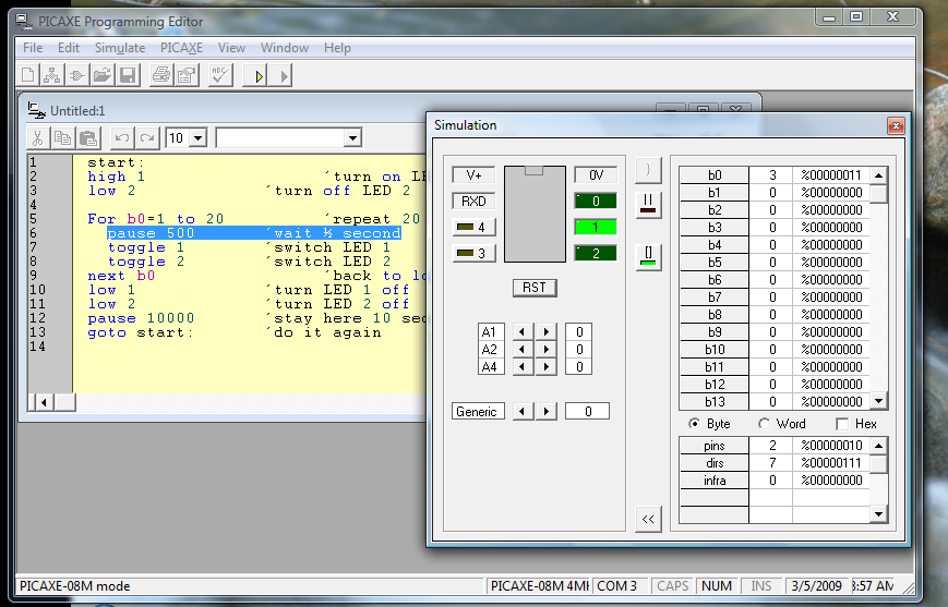
- Program 1:
- Notes:
- “start” is just a label telling the “goto”
where to go
- the program remains in the chip’s memory until it is manually
erased or overwritten.
|
|
17
|
- Program 2: modified to flash for 10 seconds and turn
- off for 10
- seconds
|
|
18
|
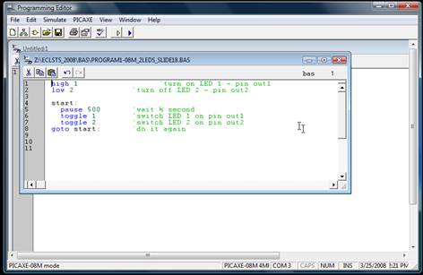
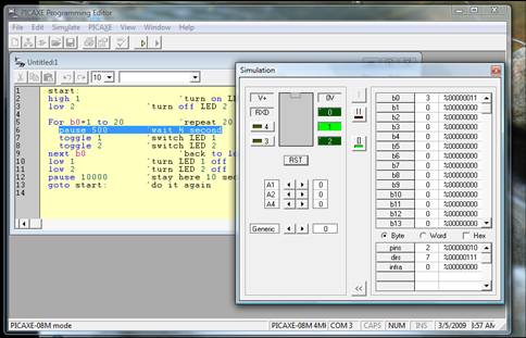
- Program simulation is built in!
|
|
19
|
- Hardware modification for button or reed switch activation:
|
|
20
|
- Program 3: modified to flash 5 seconds on each button push
|
|
21
|
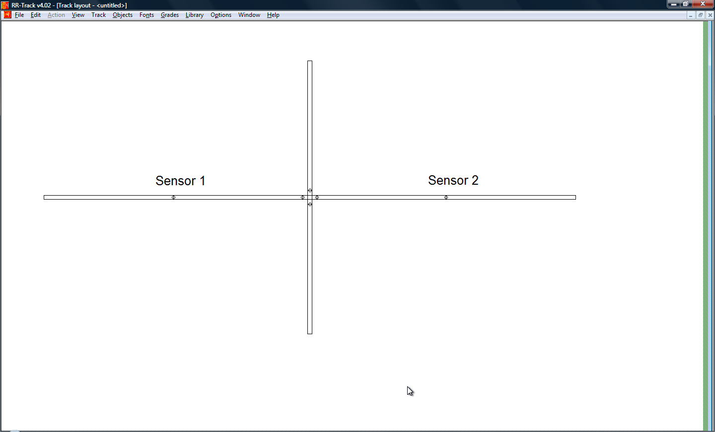
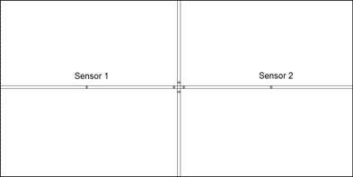
- Add a second sensor so that the light goes on when it passes one
sensor…
- …and goes off when it hits the other sensor.
|
|
22
|
|
|
23
|
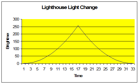
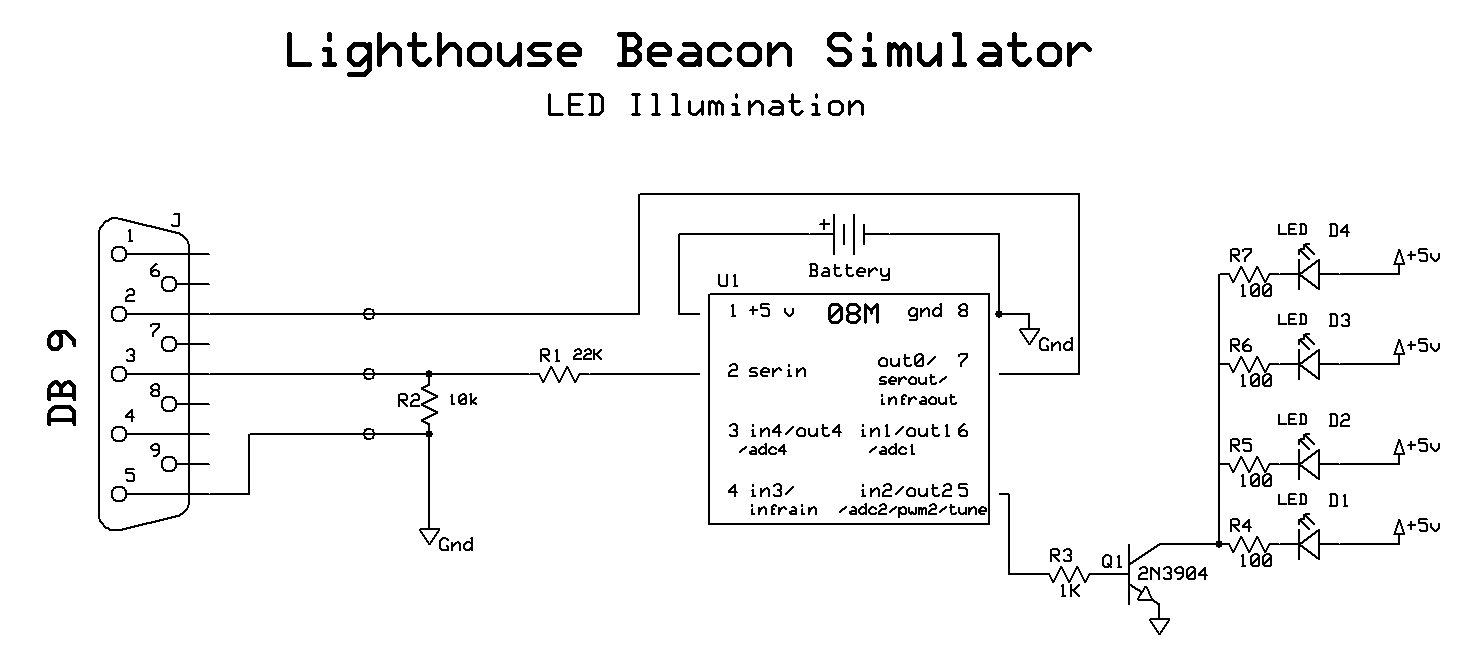
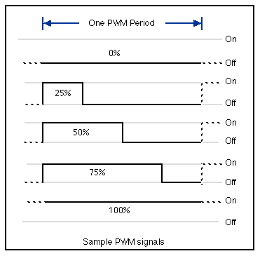
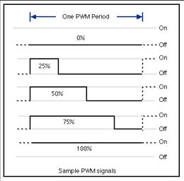
- Design objectives
- Gradually brighten a bulb or LED to near full brightness
- Momentarily flash to full brightness
- Gradually dim till off
- Delay for a set time
- Repeat
- Able to use LEDs or incandescent bulbs
|
|
24
|
|
|
25
|
- Parts
- Adds one resistor and one transistor to the original flasher circuit so
that the PICAXE can control a high current bulb
- The most significant changes are to the software
|
|
26
|
|
|
27
|
|
|
28
|
|
|
29
|
|
|
30
|
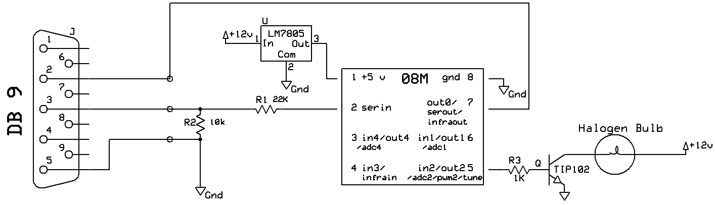
- The transistor makes it possible to drive a very bright bulb
- Substitute a motor for the bulb and you can control a train’s DC
motor!
- The size of motor is only limited by the size of the transistor
|
|
31
|
|
|
32
|
- Lights
- Motors
- Turnouts
- Relays
- Most electrically powered devices
|
|
33
|
- The two sensor crossing light control can easily be modified to make a
“safe crossing” that can be used by two trains
|
|
34
|
- When the first sensor is reached the power is removed from the secondary
line
|
|
35
|
- Once the main line train has passed the second sensor the power is
restored
|
|
36
|
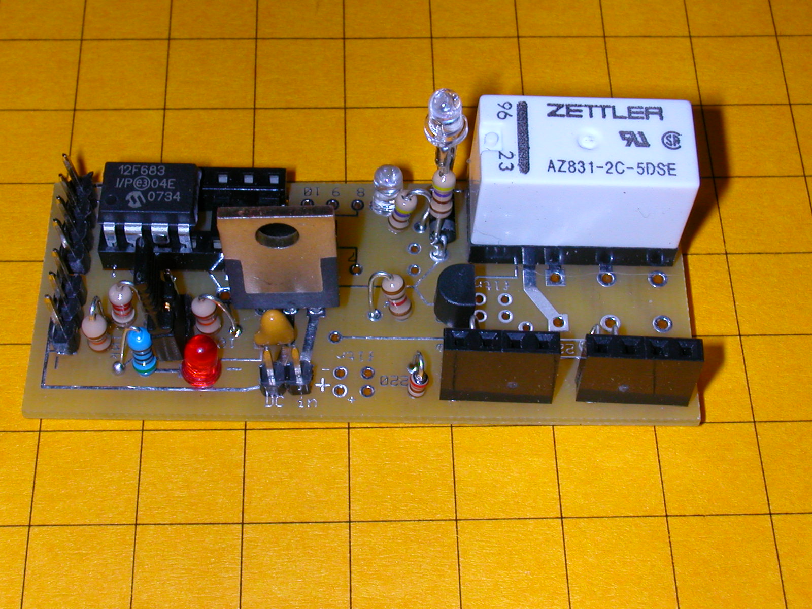
- We substitute a relay for the LEDs.
It controls the power to the secondary line
|
|
37
|
- Clever placement of diodes allows one relay to control the train
movement based on direction of travel
- The train never
stops after it has
already passed the
crossing, only
before the crossing
|
|
38
|
- More sophisticated optical sensors only release the stopped train after
sensing that the last car of the main line train has passed
|
|
39
|
|
|
40
|
|

 Notes
Notes