|
1
|
|
|
2
|
|
|
3
|
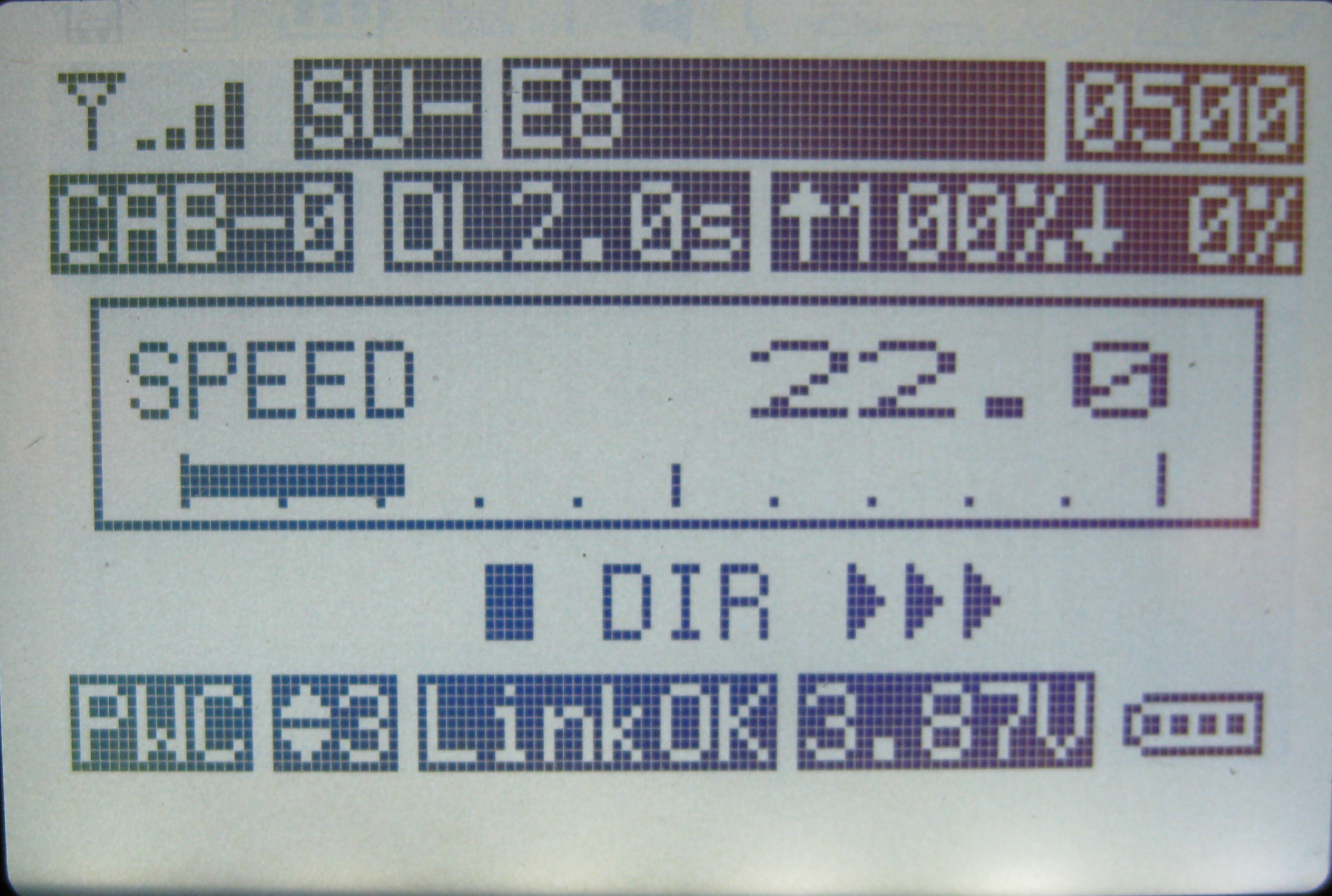
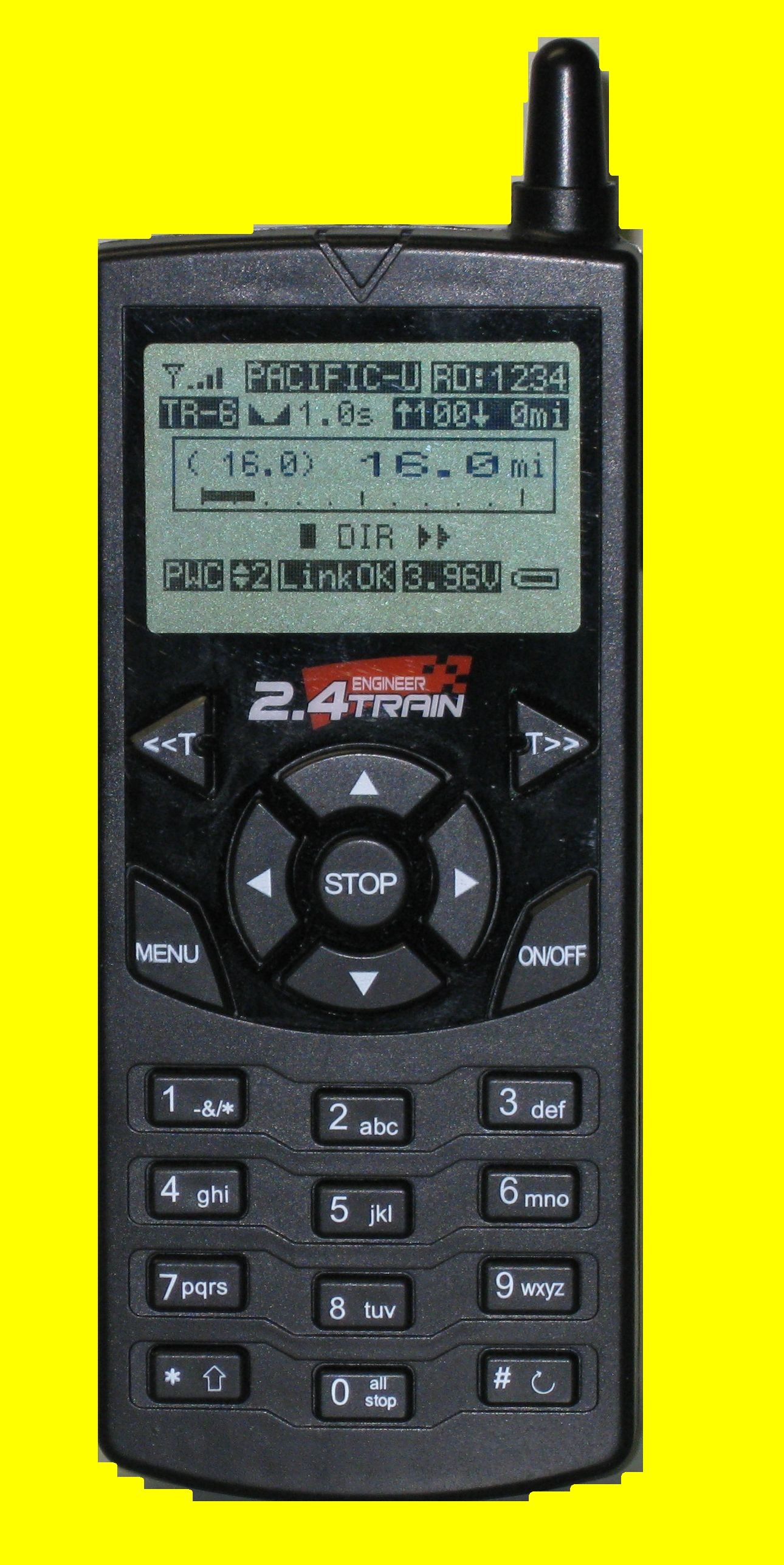
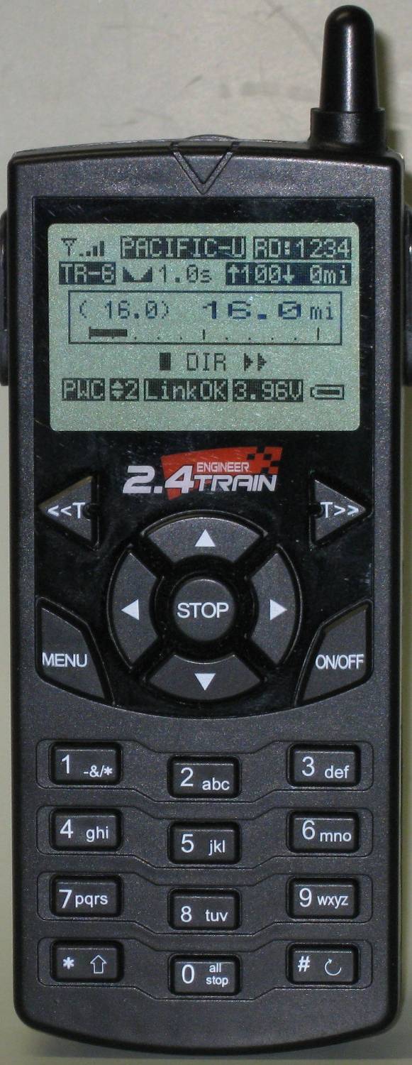
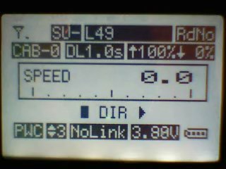
- Information about the locomotive that is being operated is clearly
displayed on a large, back-lit, graphical LCD display.
- Locomotives are identified by name and road number such as PACIFIC 5305
or MIKADO 3185
- Most transmitter control operations can be done with one hand
- Power can come from on-board batteries or track power…. Or both!
|
|
4
|
- The receiver can supply 5 amps continuously while accommodating peak
loads that can go to 8 amps.
- Six auxiliary outputs on the receiver can be used to operate sounds,
smoke units or lighting.
|
|
5
|
- The transmitter and receivers in your locomotives are designed to
communicate and exchange information about the way you want your trains
to operate. In order to
establish a link between them you need to set up options for each
locomotive in the transmitter.
- These include settings like the locomotive’s name and road number,
the top speed that you want it to achieve, the rate at which you want it
to accelerate and how long you want it to delay when its direction of
travel is changed.
- Once these parameters are set the connection between the units is
finalized by a process called “linking”. Once the transmitter and a
locomotive’s receiver are linked together they are set to communicate
and you are ready to run your train
|
|
6
|
- The second concept has to do with the cab number that is associated with
each locomotive. To link the transmitter to a locomotive you must select
a cab number that will be used to identify it.
- The cab numbers range from Cab-0 through Cab-49. This number is also
used to identify groups of locomotives that you might want to run in a
consist. Locomotives can be
operated independently or grouped for multiple unit operation.
- Cab-0, Cab-1 and Cab-2 might be used to operate three different
locomotives while Cab-3 could be used to operate those same three
locomotives in a consist.
- Changing between single unit (SU) operation and multiple unit (MU)
operation is as simple as selecting a cab number.
|
|
7
|
- Once you have an opportunity to experience the process used to operate
trains with the TE Revolution I think you will find that Aristo Craft
has found an elegant solution to what can be a complex problem.
|
|
8
|
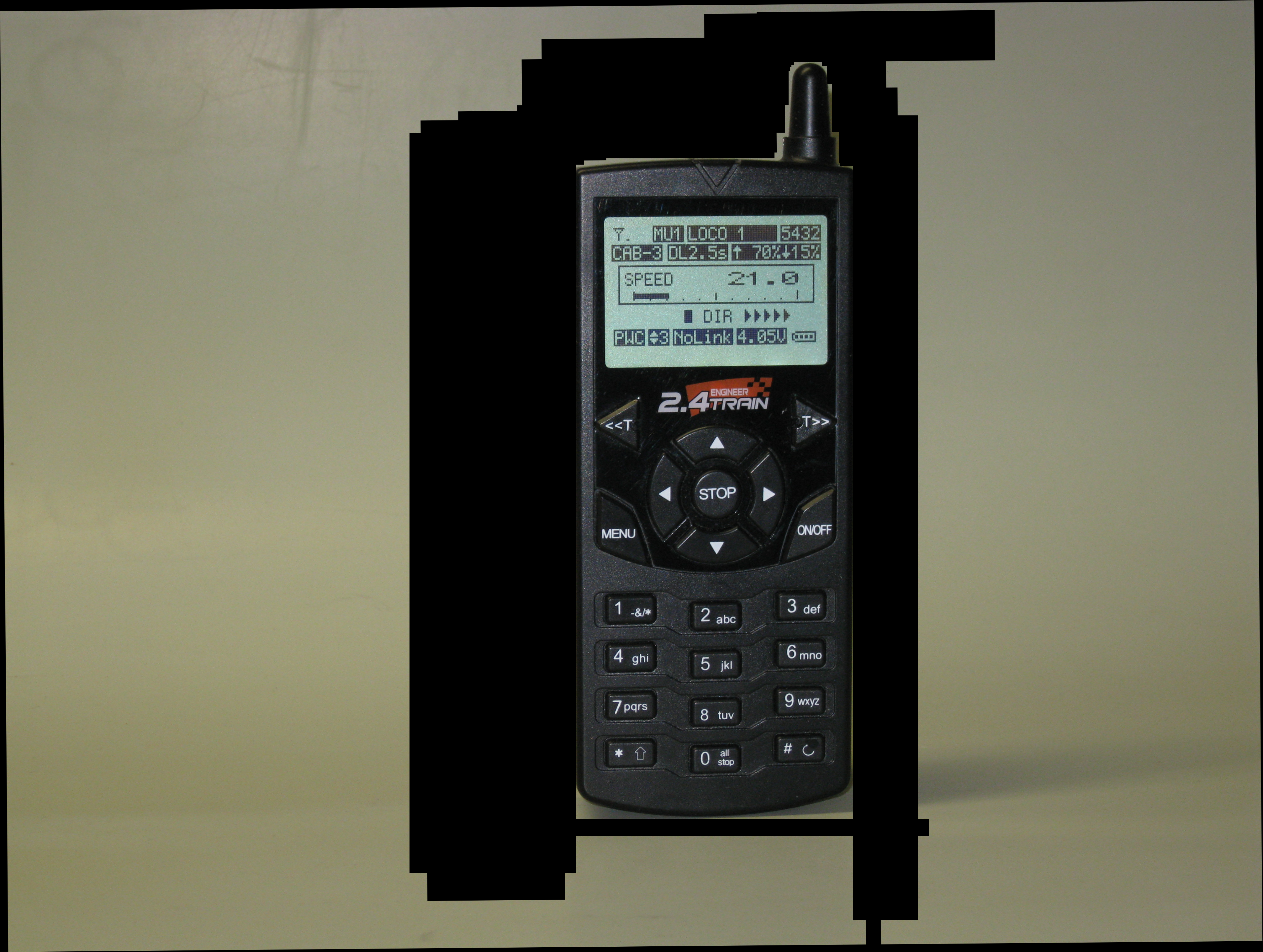
- The transmitter’s screen is designed to clearly and logically
display a great deal of information about the locomotive that is under
control.
|
|
9
|
- The transmitter has operation specific buttons and a set of buttons like
those on a cell phone that are used to enter text or numeric
information.
|
|
10
|
- The <<T and T>>
buttons select a
locomotive by cab #
- The ▲ & ▼ arrow keys increase or decrease speed
- The ◄ & ► keys change direction
|
|
11
|
- Stop stops the
selected locomotive
- Menu displays the
main menu
- On / Off turns the unit on or off
|
|
12
|
- The numeric keypad
is used like the one
on your cell phone
- Pressing “5 jkl” once
- selects “5”, pressing it two times selects “j”,
three times gives “k” and four times gives “l”
- “1 -&/*” is used for punctuation
- “#” is used to enter a space
|
|
13
|
- While operating a train, keys 1-6 operate auxiliary functions like smoke
or sound
- Holding “all stop” stops all trains
- “#” accesses the auxiliary menu
|
|
14
|
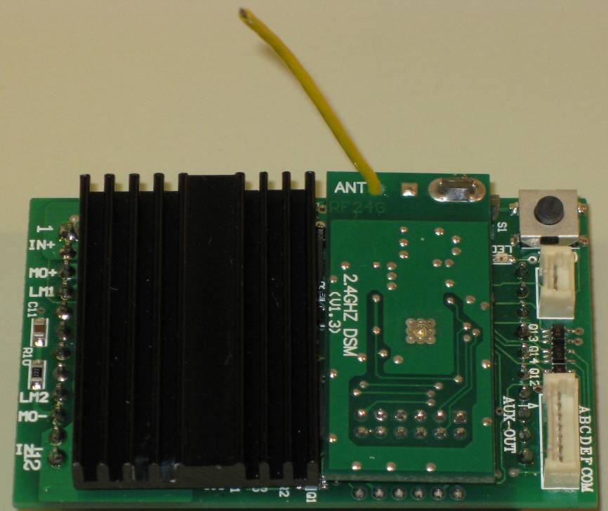
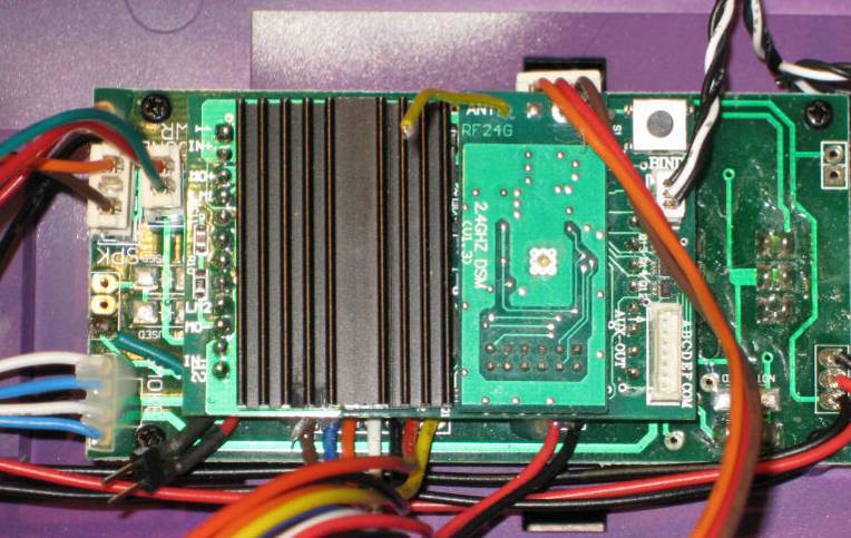
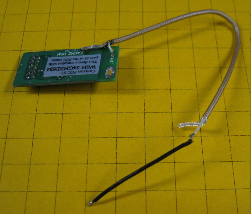
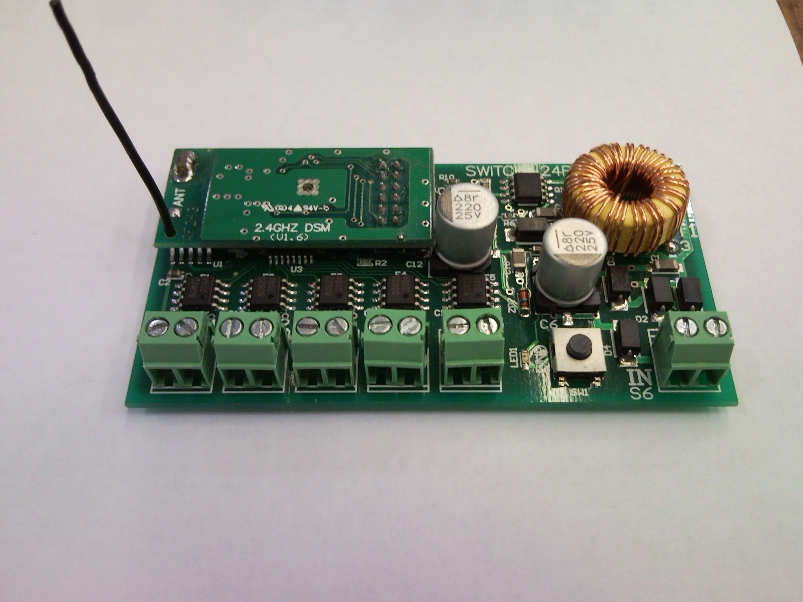
- The receiver has a
socket for the auxiliary
wiring harness
- There is a “link” switch
on the board and a
socket to mount another off of the board.
- The antenna is only 1.5” long!
|
|
15
|
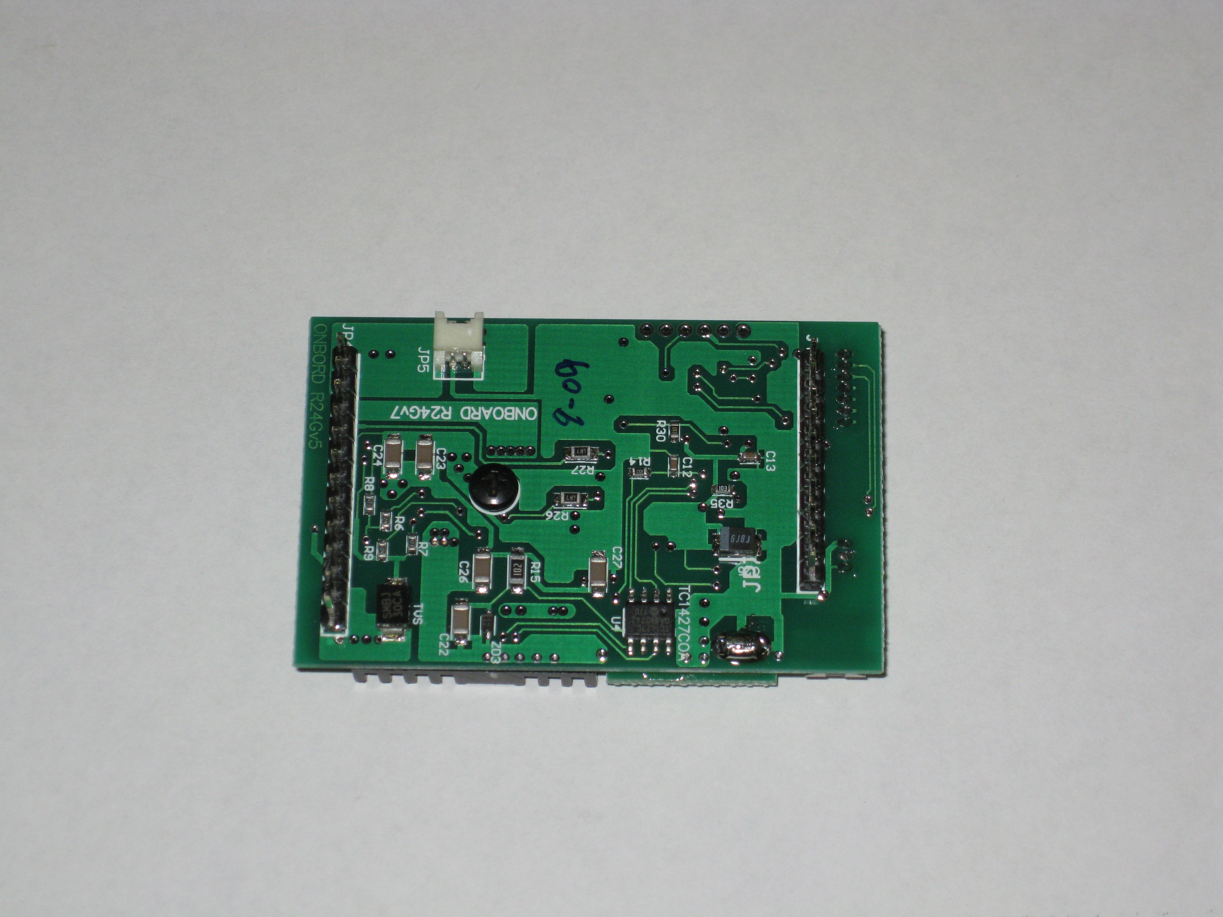
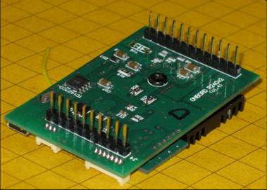
- The back of the board
has two headers that
plug into the Plug &
Play socket on most
new AristoCraft locomotives
- An optional capacitor unit can be added to enable trains to glide over
less than perfect track
|
|
16
|
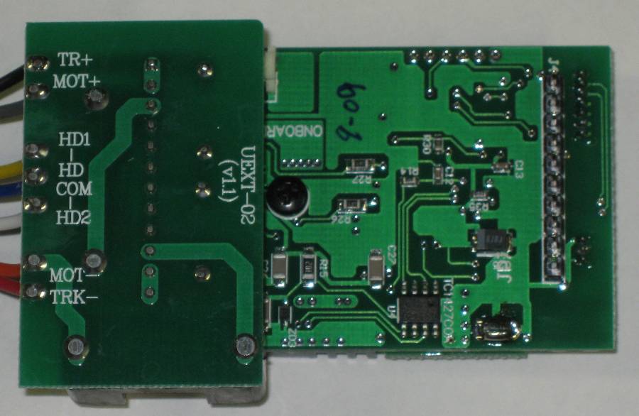
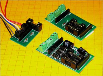
- A wiring harness can be
used for non-Plug &
Play locomotives
- Three different versions are available
|
|
17
|
- Both are supported - the choice is up to you!
- Track Power –
- NEVER MORE THAN 24V, BUT OPTIMUM IS 18-21V
- No controller needed – wire the power supply directly to the
track
- Battery Power
- Aristo Lithium Ion, Gel Cell, NiCad or NiMH up to (but not to exceed)
24 volts
- Both can be used the on same track
|
|
18
|
- Remove shell
- & locate Plug
- & Play socket
- Remove
- header
|
|
19
|
- Identify the 12 and 10 pin headers
|
|
20
|
- Carefully align the pins and insert the receiver
|
|
21
|
- Mount the external “link” switch…
|
|
22
|
- …so it can be easily accessed.
|
|
23
|
- Revolution Manual pages 31-35
- Eggliner Installation
- Aristo Forum: Non Plug-n-Play Installation Question
- Aristo Forum: Revolution TE Installation
|
|
24
|
- The Basic Procedure:
- Locate & isolate
- track power wires (2)
- motor power wires (2)
- Connect Revolution receiver red & black to track power (or battery
power)
- Connect Revolution receiver grey & orange to motor
|
|
25
|
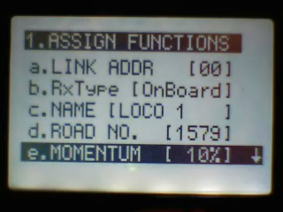
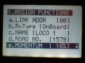
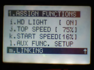
- Press MENU from the main screen
- Press 1. ASSIGN FUNCTIONS
- Select LINK address (00-49)
- Enter a NAME (up to 9 characters)
- Enter a ROAD NUMBER (up to 4 digits)
|
|
26
|
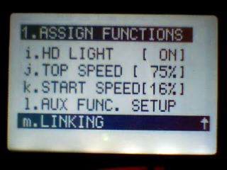
- Adjust optional
settings
- Momentum
- Delay
- Motor
- Headlight direction
- Headlight on/off
- Top Speed
- Start Speed
- Auxiliary functions
|
|
27
|
- Press the LINK button on the receiver
- Select m.Linking on the transmitter
- Wait for LINKING PASSED!
|
|
28
|
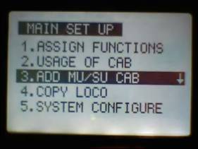
- Select 2.USAGE OF CABS
- Choose the highest Cab number that will be used (00-49)
- Hint: keep it to the least number possible to simplify use (especially
for guests)
|
|
29
|
- Select 3.ADD MU/SU CAB
- Select a Cab number
- Leave MU MODE set to OFF
- Select the locomotive by name / link number
- Menu to exit
|
|
30
|
- From the main menu use <<T and T>> to select the CAB for the
locomotive
- The ▲ & ▼ arrow keys increase or decrease speed
- The ◄ & ► keys to change direction
- Use 1à 6 to access
auxiliary functions like sound and smoke
|
|
31
|
- Repeat the steps just completed using a different locomotive, link
address, name and Cab number
- Hint: if necessary, adjust Cab maximum # under Usage of Cabs
|
|
32
|
- From the main menu select the new Cab number with <<T &
T>> and run the train
- Switch between the two with <<T & T>>
- Stop both by holding “all stop” for 2 seconds
|
|
33
|
- Consists
- accessory activation
- speed matching
- Speed curve
- Handing off control
- Installation in battery / sound car
- Using capacitor boards with track power
|
|
34
|
- Use as a track side track power unit
- Auxiliary control unit
- Reverse loops with track power
- Running from AC (or DCC) track power
- Antenna placement with all metal locomotives
- Precautions
|
|
35
|
- Up to six locomotives can be joined together in a consist (MU)
- Each will retain its own settings
- You do not need to re-link locomotives to put them into a consist!
|
|
36
|
- Set up your locomotives as single units
- Select 3.ADD MU/SU CAB
- Select a new CAB number
- Turn on MU MODE
- Indentify up to six
pre-defined locomotives under MU1 à MU6
|
|
37
|
- On the main screen select the MU’s Cab number
- Operate as you would a single unit locomotive
|
|
38
|
- While operating a consist you can assess each individual
locomotive’s accessory functions by pressing the “*”
key
- Each locomotive’s name will appear at the top of the screen as
“*” is pressed
- Use the 1à6 keys to
operate sounds, smoke and other functions
|
|
39
|
- Each locomotive can have its speed characteristics adjusted so that
mixed, dissimilar brand and model locomotives can work together
- The MU SPEED OFFSET function for MU Cabs allows for individual voltage
settings plus or minus 100%
- The MU speed offset only works for cabs within multiple unit consists.
- To access this function press the # key. You can change any locomotive
in any consist
- Caution: Link numbers MUST
be different for each locomotive within a consist for speed matching to
work properly
|
|
40
|
- Press the right or left arrow to adjust the speed of the locomotive.
- Plus [+1] to [+100] will give you a faster speed
- Zero [0] No change
- Minus [-1] to [-100] will give you a slower speed
- Pressing the STOP/ENTER button and it will take you back to zero [0]
- MU SPD OFFSET/CAB 1
- MU1 E-8
-2
- MU2 DASH 9
+3
- MU3 PACIFIC
+8
- MU4 SD45
+15
- MU5 FA1
-6
|
|
41
|
- The SPEED CURVE function allows for greater control of each
locomotive’s acceleration / deceleration characteristics.
- Found under ASSIGN FUNCTIONS / m. SPEED CURVE
- The speed curve can be set up or down from 0 to 50%.
- These adjustments allow, for example
- a very slow start followed by faster acceleration to top speed
or…
- a fast startup followed by slower accelearation
- You can experiment to find the ideal setting for each locomotive!
|
|
42
|
|
|
43
|
- Two or more operators (those with transmitters) can run multiple trains
on the same layout
- Only one operator can control a train at one time but control can be
“handed off” from one operator to another
- MULTI TX function must be turned ON.
- Under SYSTEM CONFIGURE /
e. MULTI TX
- Transmitter RF Channel & Group ID must match
- Settings under Assign Functions must match
- The last person to enter a command takes control
|
|
44
|
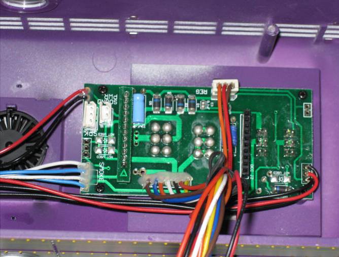
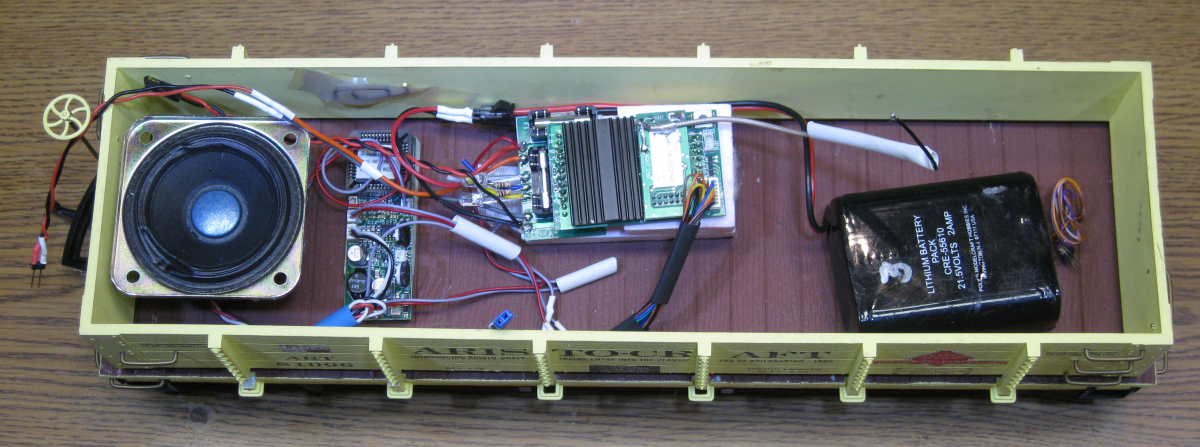
- Carries batteries (NiCad, Lithium Ion, NiMH, or Pb acid)
- Can carry a sound card & speaker
- Chuff pulses for steam locomotives can come from the trailing
car’s wheels
- The only required connection to the locomotive is for motor power
- Lights, smoke, chuff pickup are optional
|
|
45
|
|
|
46
|
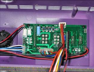
- Disconnect the locomotive’s track power pickups
- Route the locomotive’s motor connection wires to the battery car
- Optional: Route wires from battery car back to the locomotive for
lights, smoke & chuff
|
|
47
|
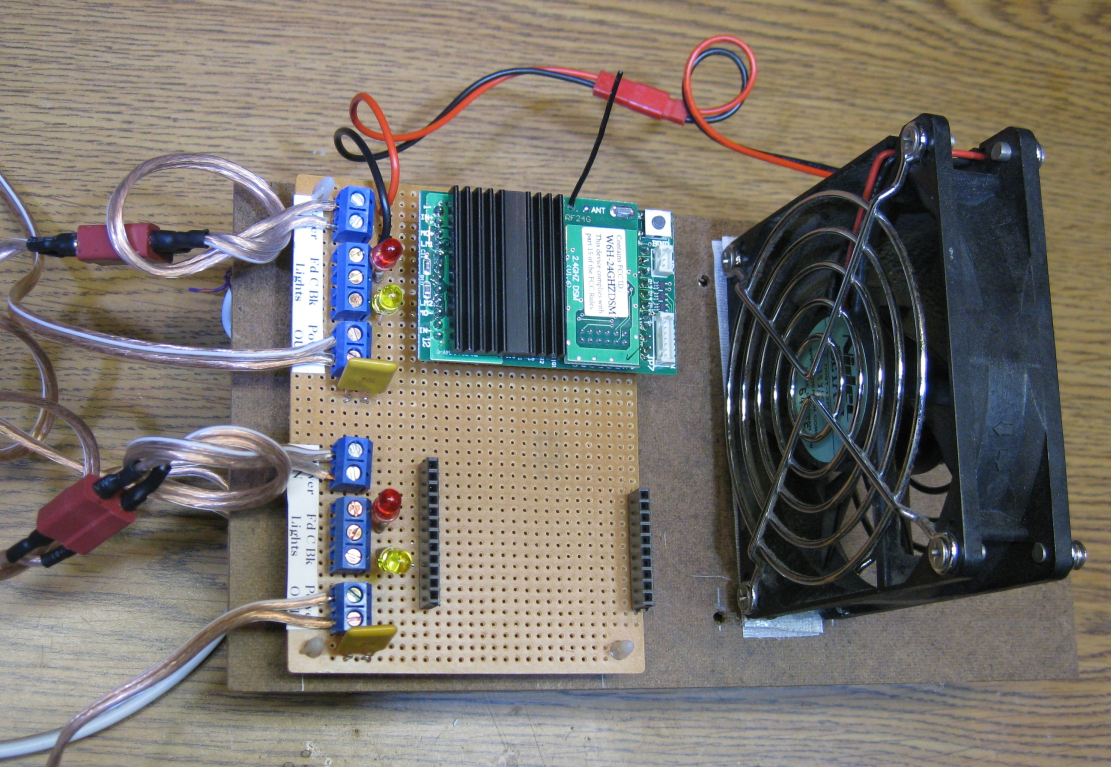
- Track Power enthusiasts can use the existing Revolution receiver to
deliver 5 amps continuous & 8 amps peak
- One or more loops can be controlled by one transmitter
- Auxiliary output channels can control switch motors and other track-side
accessories
|
|
48
|
|
|
49
|
- Each receiver’s 6 auxiliary output channels can be used for track
side accessories
- Switch motors
- Animations
- Sound
- Some will require an additional interface to operate
|
|
50
|
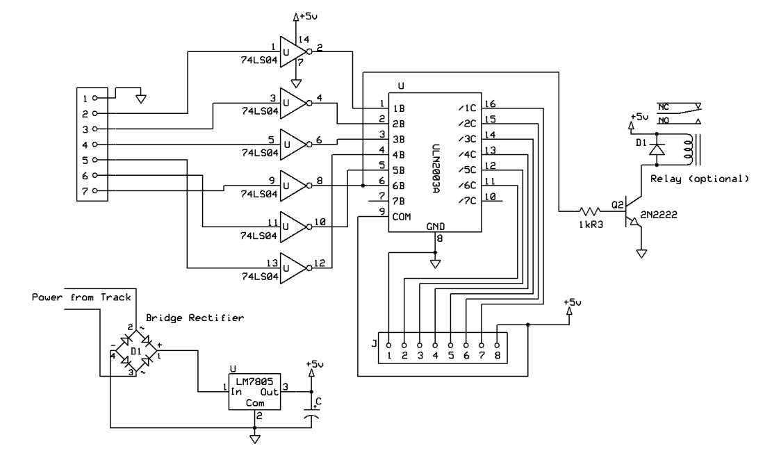
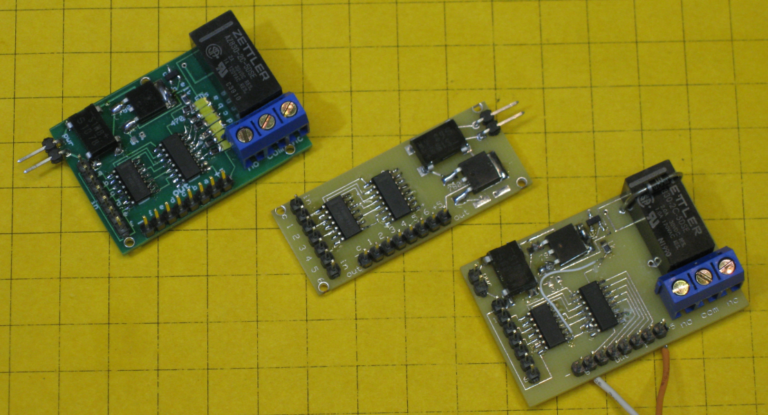
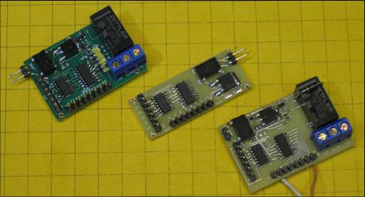
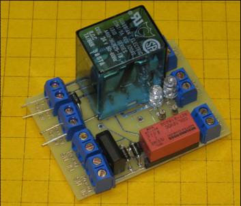
- Increases the power handling capability of the six channel auxiliary
output on the receiver
- Each output can deliver ½ amp, more than enough to operate relays
or other devices
- Buffered outputs protect the receiver from damage
- Can operate LEDs, bulbs, relays or other 5 volt loads
|
|
51
|
|
|
52
|
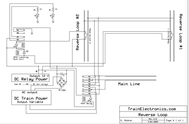
- Track power users must still be concerned about reverse loop short
circuits
- Note: this is not an issue for battery operation
- Some sort of reverse loop protection must be used
|
|
53
|
- Track power can come from straight DC (no speed controller needed)
- With the bridge rectifier non-plug & play socket track power can be
AC or DCC
|
|
54
|
- The single capacitor board (included with the starter set) gets
locomotives over dirty spots and most switch frogs
- The optional six capacitor board can keep locomotives going over very
dirty areas
|
|
55
|
- Keep the transmitter vertical to maximize range
- Keep the antenna as close to vertical as possible when installing the
receiver
- Route antennas through and outside of all metal locomotives or tenders
- Use thin coaxial cable to extend (RG174)
- See: http://www.aristocraft.com/vbulletinforums/showthread.php?t=14587&highlight=coaxial+cable
- for more information
|
|
56
|
- The Revolution receiver can be damaged or destroyed if care is not taken
during its installation and use
- Never apply voltage to the motor output connections (the voice of
experience here!)
- Never exceed 24 volts DC input to the power input connections
- Never connect loads directly to the auxiliary output connections (only
control signals)
- Keep the power requirements for lights connected to the front and rear
lighting connections to a minimum
|
|
57
|
- Will control up to five track side accessories such as switch motors
- Accessories can be sequenced
- Multiple controllers can be “ganged” to allow the operation
of more than 5 accessories with a single button push
- Availability: by the end of 2009
|
|
58
|
- TRAIN ENGINEER REVOLUTION
- Instruction Manual for Revolution Train Engineer (2009) - .pdf
- Revolution Train Engineer Addendum - .doc
- Revolution Train Engineer QuickStart - .doc
- Installation instructions for using the Revolution with Dallee sound
boards (Note: This will take you off Aristocraft.com and directly to
Dallee.com)
- CRE57073 Smoke Board Installation Instructions for C-16 Tender - .pdf
- Revolution Train Engineer Capacitor Board Instructions - .doc
- Sound card installation for Revolution Train Engineer - .pdf
- "Inside The Train Engineer Revolution" by David Bodnar -.pdf
- 2.4 Ghz Revolution Train Engineer Instructions
- Aristo-Craft Eggliner Installation Instructions - .doc
|
|
59
|
|
|
60
|
|

 Notes
Notes