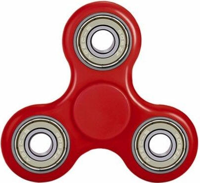
| Fidget Spinners have become the latest fad. I
was curious about them so I ordered one from eBay and spun it
a bit. While it was great fun for a short time it left me
bored and wondering what else it could be used for.
Having once taught science to elementary school students I remembered trying to explain to them how an electric motor worked. The bearings in the spinner and the overall shape reminded me of the armature in a simple DC motor. I set about building a few different motors, ranging from a very simple one to one that is way too complex. I found this part of the spinner experience was more fun that just spinning them. This article presents what I have done in hopes that you might enjoy experimenting with them, too. |
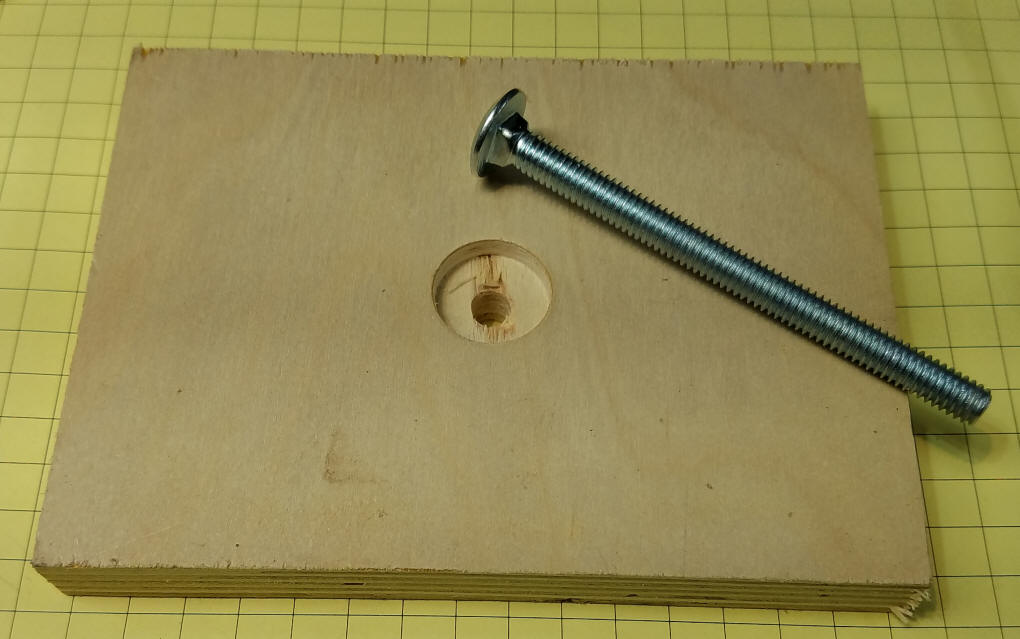
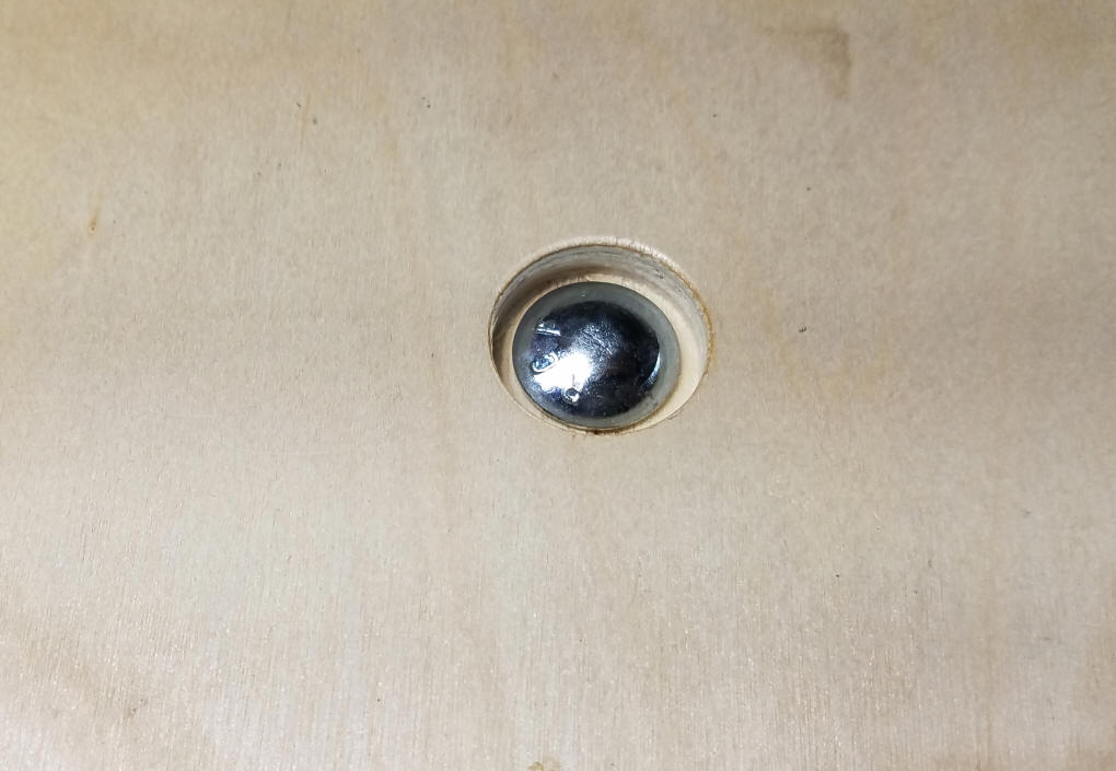
| A Sturdy Base for Experimentation The base for all of the following examples is the same. It is composed of a 4" or 5" square piece of pine or plywood about 3/4" thick. A 5/16" hole is drilled in the center to accommodate a 5/16" x 3" carriage bolt. The bottom of the hole is drilled out with a Forstner or spade bit to countersink the head of the bolt.
The 5/16" bolt fits nicely inside of the center bearing of the spinner. Additional nuts can be put onto the bolt to raise the spinner above the platform.
|
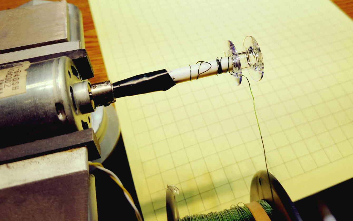
| Building the Electromagnet While an electromagnet can be made in many ways and just about any one will work for these experiments I decided to wind mine onto an empty plastic spindle that would normally be used to hold thread for a sewing machine. The wire I used is called magnet wire and is copper wire coated with a colored enamel coating that must be removed from the ends to make connections to the other parts of the motor. For some coils I used 34 AWG magnet wire and for others I used 28 AWG wire. They different coils worked equally well. I put the empty spindle onto the shaft of a hobby motor that was placed into a vice. I applied a low voltage to the motor. Just enough to spin the shaft but not too much that I couldn't stop it spinning by pulling back on the wire. See the video for more information on how to wind the coil.
The coil was mounted to a piece of wood or acrylic so that it can be mounted to the same 5/16" bolt that holds the fidget spinner.
|
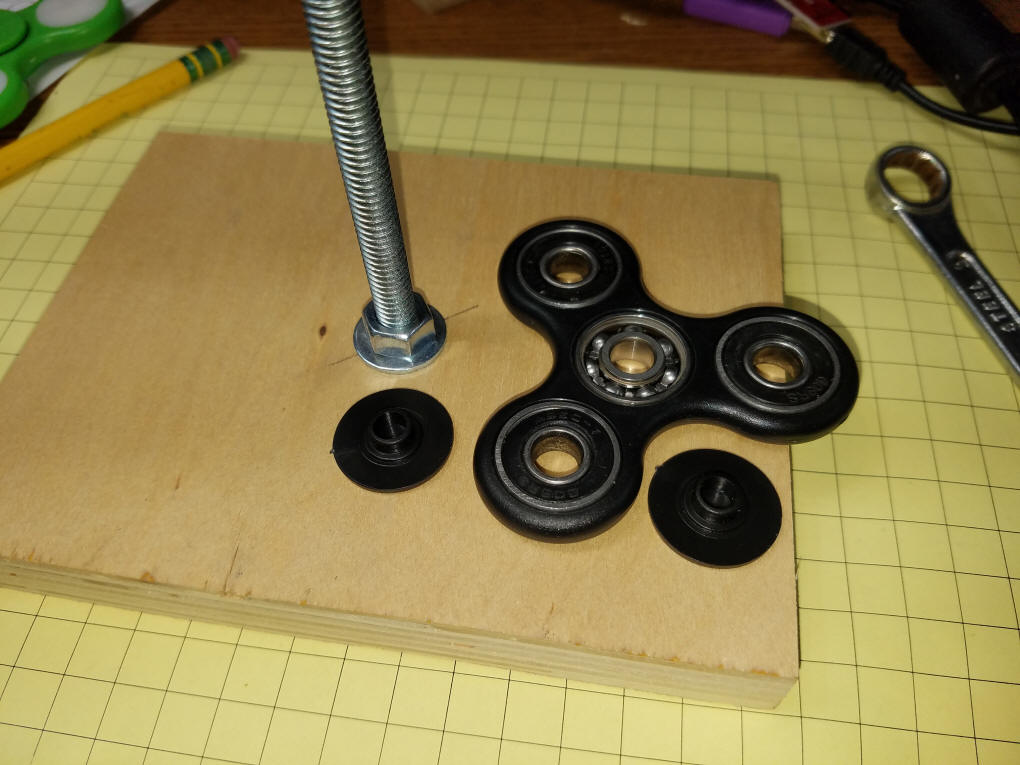
| A Simple "Spinner" Motor
The simplest motor I could come up with uses only a few parts:
The circuit is quite simple. A magnet is placed on each of the three outer arms. Make sure that the same pole faces up on each arm or the motor may not work. I used neodymium magnets, also called rare earth magnets. It is important that all three magnets are identical so that the spinner is balanced. An electromagnet is placed over the arms so that they pass by it as the spinner rotates. A micro switch is hit by the arms as they pass by. This turns on the electromagnet pulling the nearest magnet towards the electromagnet. As the arm & magnet approach the electromagnet the switch turns off allowing the magnet to coast by. Spacers can be added between the nuts and the coil mount to position the electromagnet just above the magnets - close but not touching! I found that the switch and electromagnet needed to be about 90 degrees apart for the motor to work well. See the video for more details about placing the switch and coil. The schematic is very simple, just the switch, coil and power supply or battery.
|
| A Simple "Spinner" Motor with
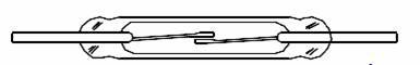
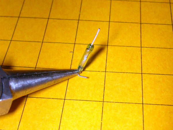
a Reed Switch The spinner that uses the micro-switch works well but could be better. The impact between the spinning rotor and the paddle on the switch surely slows things down. What is needed is a non-contact device that will turn the electromagnet on and off as the micro-switch did. A reed switch fits that description as it is a small switch that is turned on when it comes near a magnetic field.
The switch is made up of two small metal plates (reeds) that are magnetized so that they normally oppose one-another keeping the switch off. When the glass vial that holds the reeds comes close to a magnetic field the reeds touch turning the switch on. One word of caution when working with reed switches. Never try to bend the wires that extend from the glass vial by holding the glass and bending them - the glass will break ruining the switch. Hold the wire close to the glass with a pair of needle nose pliers and bend from that point.
|
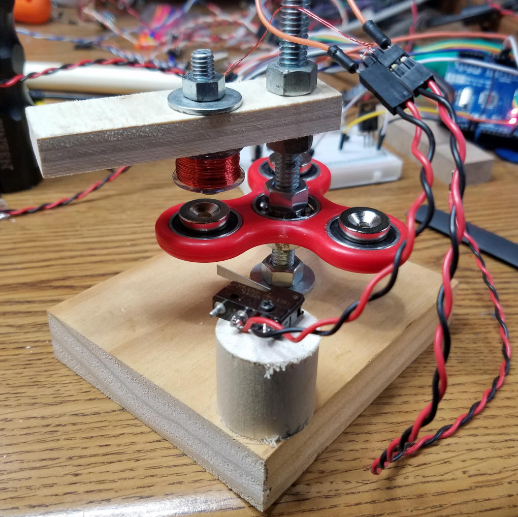
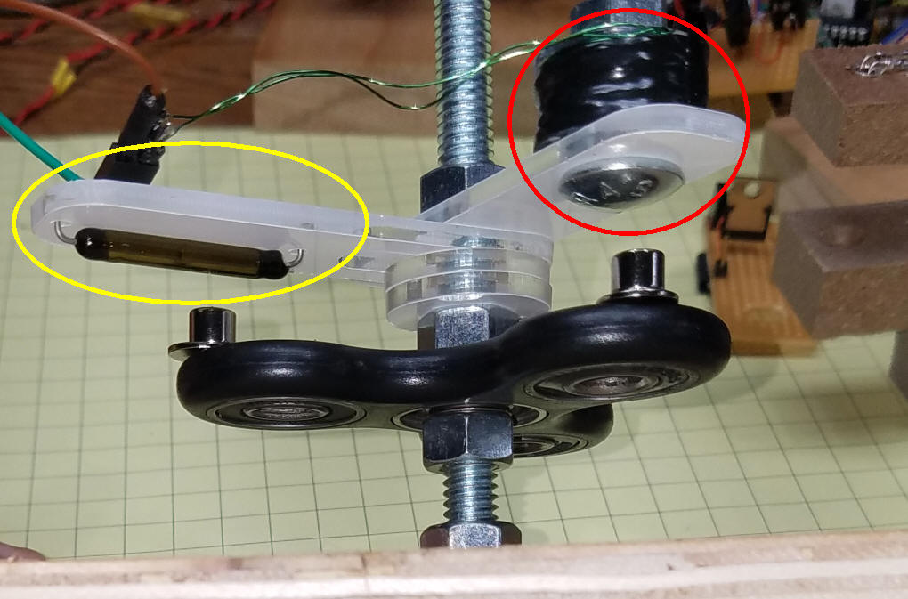
| Here we can see the rotor with magnets on
the ends of its arms. The electromagnet is circled in red and
the reed switch is circled in yellow. Two plastic
washers (spacers) were used to adjust the space between the reed
switch and the magnets on the fidget spinner.
|
| The reed switch schematic is almost
identical to the one that uses the micro-switch. The diode
(D1) is optional but is likely to extend the life of the reed
switch. This is due to a back pulse (back EMF) being generated
when the coil is turned off. This pulse of energy can weld the
reed switch's magnetic plates together so that it is always on.
|
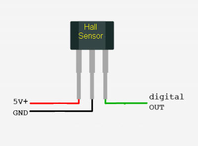
| A Solid State Magnetic Sensor, the Hall
Effect Sensor Many brushless motors use Hall sensors, a 3 pin solid state device that senses a magnetic field.
This device cannot control a high current device like the electromagnet so it must connect to the coil through an interface that triggers a power transistor whenever the magnet goes past it.
The additional parts are a common NPN transistor (2n2222 or equivalent) and a Mosfet power transistor (IRL520 or similar). Here the diode that goes across the coil's terminals is not optional as it was with the reed switch. If the diode is not in the circuit the Mosfet will fail after some amount of use due to the back EMF pulses damaging it.
|
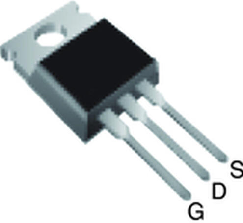
| An Optical Switch While the reed switch works very well and doesn't directly touch the rotor it still can slow down the rotation a bit as each time the magnet passes it they are attracted magnetically. An optical switch, on the other hand, has no physical or magnetic connection to the rotor. It can be made from a few additional parts. We use the same electromagnet and the same magnets on the arms of the fidget spinner. We then add an LED that is aimed at a phototransistor that will be in shadow when the rotor passes by. In addition we need a transistor that acts as an on/off switch to activate the electromagnet. A standard NPN transistor will probably work but the most efficient device that I had on hand was an IRL520 Power Mosfet. This device has a very low resistance when turned on and will easily handle the power drawn by the circuit.
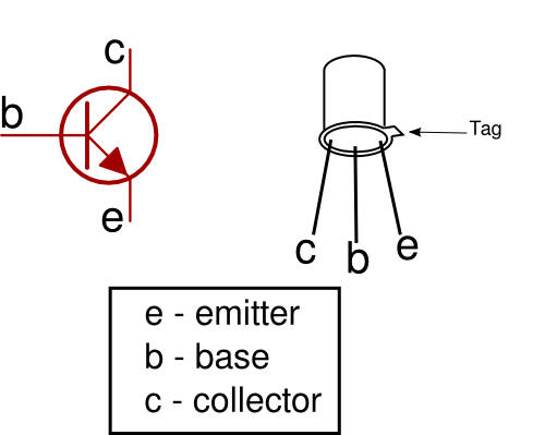
The phototransistors that I used are in a metal can and have three leads. The center lead (the base) is not used and can be snipped off. The tab is next to the emitter. Phototransistors like the ones I used are available from eBay and Amazon.
The schematic is very similar to the one used with the Hall sensor.
|
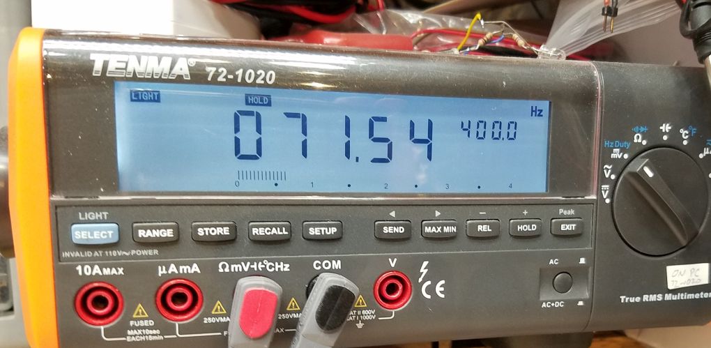
| How Fast Does it Spin? You can measure the speed of the Fidget Spinner by hooking up the circuit with the phototransistor to either a multi-meter that can measure frequency or to an oscilloscope. Connect the negative probe from the meter or scope to ground and connect the other probe to the output of the phototransistor (Q1) just below resistor R1. This photo shows my meter set to Hz Duty. The measured frequency is 71.54. That is the number of times that the light sensor was put into shadow by the spinner arms. Since there are three arms we need to divide by 3. That gives the speed in revolutions per second. To get revolutions per minute multiply by 60. Or you can just multiply the displayed reading by 20 since that is the same as dividing by 3 and multiplying by 60. In this case the spinner is rotating at over 1400 RPM. Not bad for a simple toy!
This screen is from my oscilloscope and shows a speed of a bit over 44 Hz, giving a speed in revolutions per minute of almost 900.
|
| Going Further I hope you have a chance to give some of these experiments a try. If you want to see what can be done by hooking up the coil and a sensor to an Arduino for even more experiments please drop me an email and let me know. dave@davebodnar.com
|