Franklin Christmas 2008 Display Controller
Revised 10-21-08
|
The objective of this project is
to design and construct a controller that will activate two trains
when visitors press a button on the outside of the display window.
The button will be connected to a radio control transmitter which
will activate a matching radio control receiver inside of the
controller.
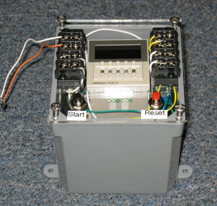
The controller will have a timer
(Omron HC3A) that will be set to run the two trains for some amount
of time each time the button is pressed.
Rather than having the controller
make / break 110 volt power connections to the two train's power
supplies it will break the low voltage power that each power supply
sends to the track.
One train will be on a loop of
track and will proceed forward whenever the button is pressed.
The other train will be on a
point-to-point layout and will go back and forth under the control
of a BARC controller whenever the button is pressed. Note that
no attempt will be made to remember the position of the train when
it stops so that its first movement upon being restarted may be in
the opposite direction from the way it was moving when stopped.
|
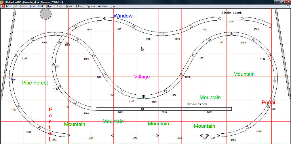
Layout
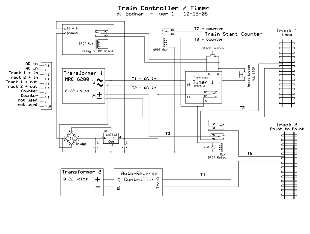
Controller Schematic & Notes
Power for the controller will come from the AC out connections on the MRC
6200 power supply. One track power lead from the MRC 6200 will go directly
to the track while the other lead will go into the controller via terminal 3 and
to the track via terminal 5. This connection will only be live to the
track when the system is operating.
The other power supply will go to the BARC. One of the track
connections from it will go directly to the point-to-point track while the other
will go into the controller via terminal 4 and to the track via terminal 6.
Again, it will only be live during the time that the Omron timer is active.
An optional counter (from a pedometer or similar unit) can be connected to
terminals 7 and 8 and will increment each time the button is pushed. It is
activated by a small SPDT relay that is wired in parallel with the DPDT power
relay.
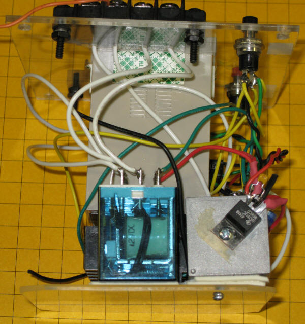
The controller will be housed in a 4" x 4" x 5" plastic enclosure with the
Omron timer coming out of the top. On top will also be the connection
strip, a start button and a reset button that will stop the trains. Inside
of the box will be the Omron timer, the radio control receiver / relay, a power
supply with two filter capacitors and a DPDT relay that will activate the
trains.
Outside Transmitter Box
A locked box will house the transmitter and a large, robust button that will
be used to start the trains. The transmitter will be battery operated.
The box will be affixed to the outside of the building by screws.
Completed Controller
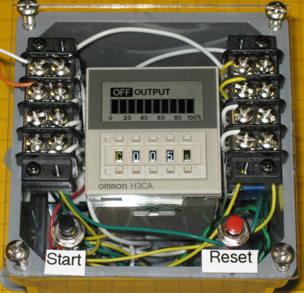
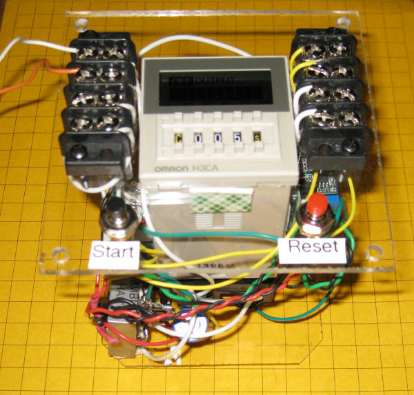
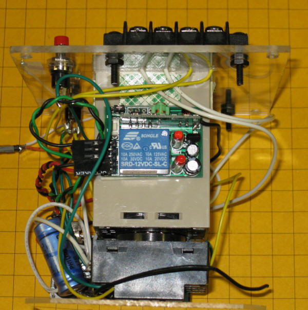
The device in the lower right is a 7812 voltage regulator that is screwed to
the large metal case of the bridge rectifier.