LEDs 103 - Turning them On and Off
Revised 04-07-2009
Click here for a short Latching Reed Switch video
The last installment in this series (LEDs 102 - Use On Board Trains) ended with a few thoughts about turning battery powered LEDs on and off. In this article I would like to explore several options for turning LEDs, and other things on your railroad, on and off.
Topics will include:
Latching reed switches
Latching dual-coil relays
Building a flip-flop circuit
Employing a PICAXE to do some more sophisticated on & off stuff
On / Off Switch Requirements
There are a few things to consider when selecting a switch to turn battery operated devices on and off.
It should be relatively inexpensive. No more than a few dollars per switch, preferably less.
It should be easy to mount in an out-of-the-way location so that it will not detract from the look of the car or engine.
It should be easy to access.
It should draw little or no power when off.
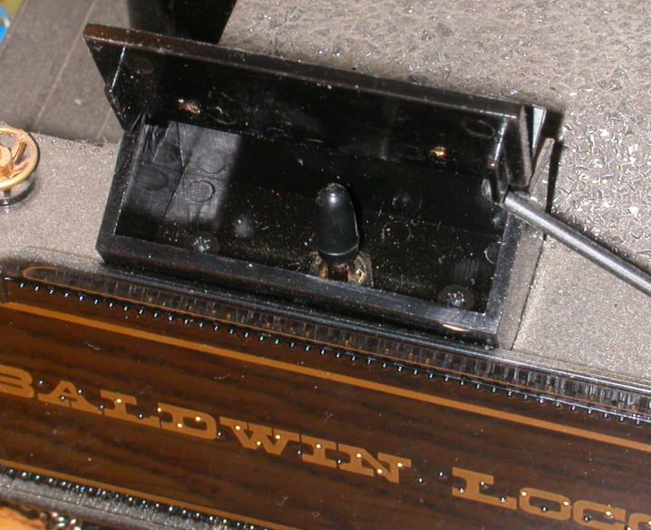
A simple on/off toggle switch meets the first and last requirement and, depending on where you put it, the other two as well. I have mounted small toggle switches under cars and tenders to do a variety of things and find them to be a good solution so long as I can remember where they are located under the car! The switch pictured here is inside of a tool box on a tender.
Reed Switches
A reed switch is a magnetically activated switch that is frequently used in model railroad applications. They are also commonly used to trigger burglar alarms when a window or door is opened. Most are composed of a small glass tube that contains two small magnetized contacts that normally do not touch. This makes most reed switches Normally Open, sometimes referred to as NO as opposed to NC switches which are Normally Closed.
When a magnet is brought near the switch the two contacts come together and the switch closes. When the magnet is removed the contacts spring apart and the circuit opens. If you would like more information on reed switches they were covered in some detail in my article Garden Railway Sensors - Part 1
As I mentioned in the last article you can use one of these common reed switches to turn LEDs on and off by gluing the reed switch to the inside of the roof of a car. Placing a small magnet on the top of the car will turn the LEDs on and they will go off when it is removed. As you can imagine this presents a few problems. You have to find a place where the magnet is not likely to fall off as the train moves around the railroad and then you have to disguise the magnet as something that belongs on top of a car. With the likelihood of losing magnets approaching 100% when used in this manner we may want to rethink this option!
Latching Reed Switches - CAUTION FRAGILE!
A latching reed switch, that is a reed switch that latches on and stays on even with the magnet removed, would be an ideal solution. In LEDs 102 you may recall that I briefly mentioned that latching reed switches were something of a rare commodity. Since then I came upon a supplier for latching reed switches on eBay. I ordered half a dozen (at $1.50 each plus shipping) for experimentation. The good news is that they do work as advertised. The bad news is that I broke the first three that I used during testing and expect at least one or two more to bite the dust in the near future!
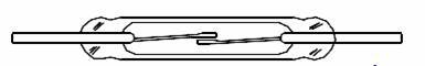
This photo shows the latching reed switch (on the left) and a traditional NO reed switch on the right. Except for size they appear to be identical.

It turns out that these reed switches are extremely fragile. I broke one by dropping it a short distance onto a carpeted floor. Another broke as soon as I put alligator clips directly onto the contacts for testing. The stress on the glass was too much for it. By then I knew that there was a problem. I soldered flexible wires to the contacts on the third switch and glued its glass cylinder to a piece of wood for testing. One of its contacts pulled right out of the glass body of the switch within a few hours of testing. To say the least these are the touchiest reed switches I have ever seen.
On a more positive note they do work as expected. If you bring one pole of a permanent magnet near the reed switch the contacts within the glass tube come together and current flows. If you carefully remove the magnet the contacts will stay together and your LEDs or whatever is connected to the switch will stay on. To turn the switch off turn the magnet over and bring the other pole near the switch. The contacts will relax and separate breaking the circuit. Their operation is not completely flawless. I found that the switches sometimes turned off as I removed the magnet that was supposed to turn them on. Taking two or three tries to turn the LEDs on or off was an irritation but not a major problem.
No current handling specifications were supplied with the switches but they should have no trouble handling the power drawn by any number of LEDs. I would not, however, try to use one of these switches to directly control a motor or string of incandescent light bulbs! The contacts are likely to fuse together and never open again.
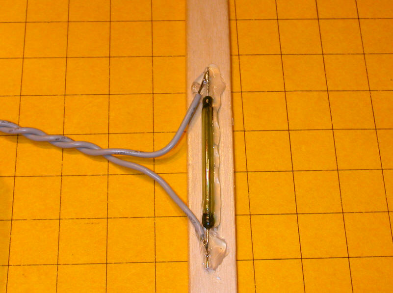
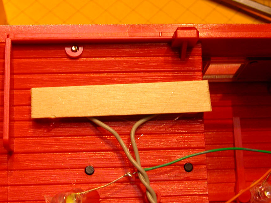
One of these switches can easily be installed to control the LEDs in the caboose that I showed in the last article. In light of the comments above I took some precautions with the installation. First I soldered thin, flexible, stranded wire to each of the switch's contacts. They are the wires protruding from the ends of the glass tube. NEVER attempt to bend these wires without using two pairs of pliers. One on the end of the wire closest to the glass and the other towards the end. If you grab the tube and try to bend with your fingers you can guarantee a broken switch!
I then hot melt glued the reed switch and the ends of the wires to a piece of pop sickle stick.
Finally I hot melt glued the whole thing to the top of the roof with the reed switch's glass body directly against the plastic roof. This placement allows the magnet to get as close as possible to the contacts inside of the switch.
Here is the switch before gluing...
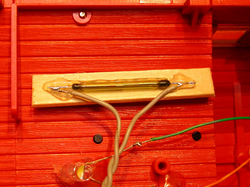
... and after gluing.
I noted the position of the reed switch and was able to turn the lights on and off with a small rare earth magnet.
Good News for Experimenters
I have some good news for those of you who would like to experiment with latching reed switches. I located another source for latching reed switches. They look and operate the same as the ones from eBay but don't appear to be quite as fragile. More importantly I got them at a better price and can sell them for $1.00 each rather than the $1.50 charged on eBay. Drop me an email if you want to try some out.( dave@davebodnar.com ) (Note added 1-7-2015 - my supply of latching reed switches is about gone - those that remain are available for $2.00 each.)
Latching Relays
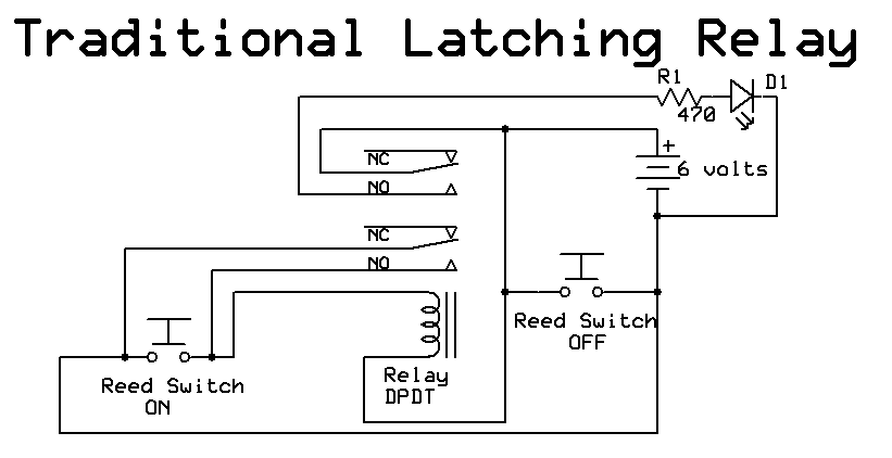
Even though the latching reed switches will successfully turn our LEDs on and off and, more importantly, draw no power when the circuit is off, I continued to look for another way of accomplishing the same objective using more traditional parts. I have wired standard DPDT relays to latch on many times in the past and thought about wiring a relay that would latch on when activated by a reed switch and would turn off when another reed switch briefly shorted out the coil releasing the contacts. I knew that this would work but there are two problems with using a latching relay on a battery operated circuit. The most significant issue is that relays draw a good bit of current when they are on, something that our batteries should not be asked to supply. The other issue is that the reed switch that would be used to short the coil, turning the relay off, would probably fail prematurely due to arcing between its contacts.
In this schematic you can see that the reed switch labeled "ON" applies power to the relay's coil closing both sets of NO (normally open) contacts. One set of contacts applies power to the LED and the other bridges the "ON" reed switch keeping power flowing to the relay coil. The other reed switch shorts the battery when it closes turning the relay off. The impact of the direct short on the circuit could be lessened somewhat by putting a small resistor in series with the "OFF" switch but it still would draw much more power than the LEDs when energized.
A Different Kind of Latching Relay
After doing a bit of research and exploring on the Internet I came across just the thing I was looking for: a latching relay with two coils rather than the single coil found on traditional relays. When power is briefly applied to one coil the relay contacts toggle in one direction and stay there, even when the power is removed. Applying power to the other coil reverses the connection to the contacts and they stay in that orientation when power is removed. I ordered a few different sample units for experimentation and find that they provide a perfect solution to the problem of turning our LEDs on and off.
All that is needed is a latching relay with two 5 volt coils and two standard reed switches. One reed switch is glued to the inside of the front of the car's roof and the other to the back. Briefly placing a magnet over the front reed switch turns the LEDs on and passing the magnet over the back reed switch turns them off. When off no power is consumed by the circuit so the batteries are not drained while the car is in storage.
These photos show two different dual coil latching relays.
Note that each has 10 pins, not the normal 8 that are found on most DPDT relays.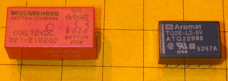

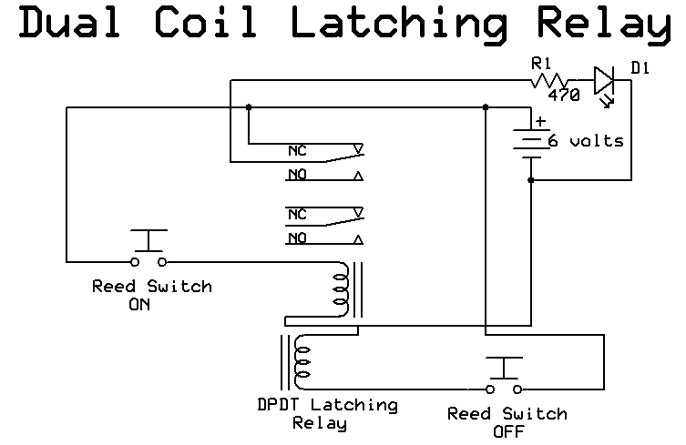
In this schematic you can see that the "ON" switch applies power to the top coil and that the "OFF" switch applies power to the lower coil. You can connect the LEDs to either the contacts labeled as NO or NC as the contacts toggle back and forth and there is really no normally open or normally closed position.
Flip-Flop Circuit
If you would like to control the LEDs with an electronic circuit that only needs one reed switch to toggle the LEDs on and off a "Flip-Flop" circuit is just the thing. They can be made with any number of integrated circuits. Here are two schematics. The first utilizes a 4013 and the second a 4027.
The circuits are very similar. Resistor R2 and capacitor C1 are used to "debounce" the reed switch. Debouncing is necessary as most switches, reed switches included, repeatedly connect their contacts a number of times whenever they are activated. This switch bounce makes sensitive circuits, like the flip-flops, interpret these bounces as multiple button presses. This can easily leave the switch on when you want it off and visa versa. The debouncing circuit smoothes things out so that only one key press is seen each time the reed switch is near a magnet.
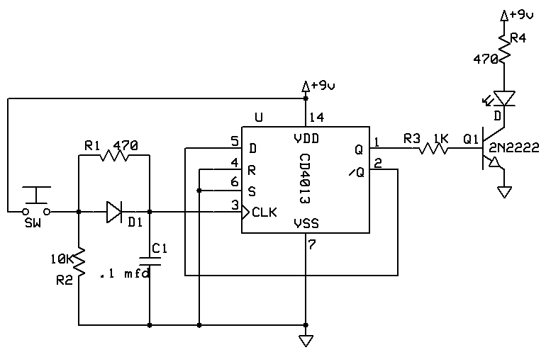
The circuit for the 4027 is almost identical. The 2N2222 transistors are not needed if only one LED is powered but become necessary if you want to power 3 or more LEDs. Even though both circuits show 9 volts on the power connections either works well with 3 or 4 AA batteries.

The main advantage of these circuits is that only one reed switch is needed to turn lights on and off. The disadvantages are the number of components and the fact that the circuit will draw a small amount of power even when the LEDs are off. Depending on the type of batteries used they will be depleted over a few days or weeks even if the LEDs are off.
A Simpler Circuit
There is a simpler circuit that costs little more than those above and gives infinitely more flexibility turning your lights on and off. The chip I am recommending is the PICAXE that I have discussed on many occasions here on LSOL. The simple PICAXE 08M sells for about $3.00 and can do all that the 4013 and 4027 do with fewer external components.
Here is the basic circuit. As you can see all that is needed is the PICAXE and a few resistors. One LED can be safely connected directly to a pin on the PICAXE. Multiple LEDs can be driven by the same NPN transistor as in the other circuits.
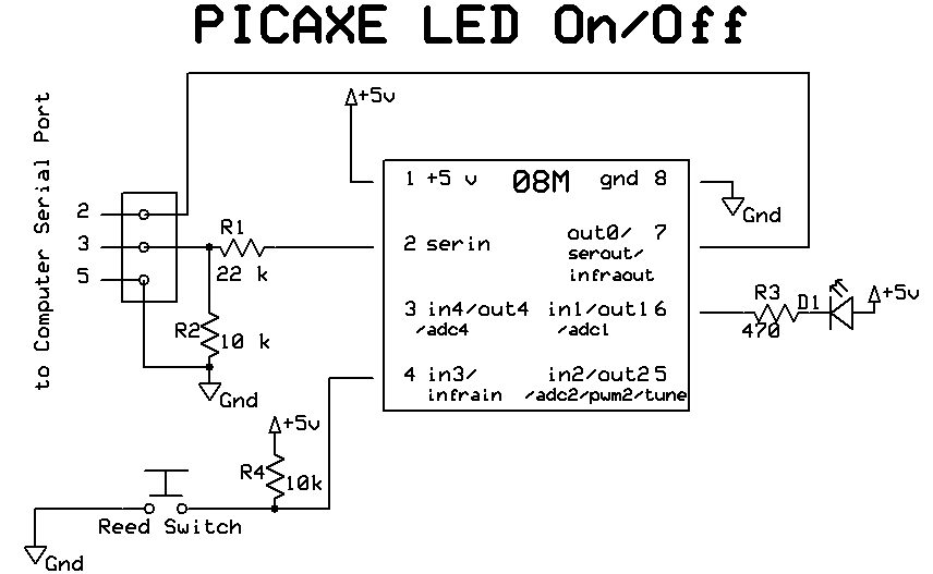
The reed switch here is also subject to switch bounce but we can take care of that in software within the PICAXE. Lots simpler than using a resistor / capacitor circuit! The program below is all that you need to make it all work. Note the "pause 500" statement. This tells the program to wait 1/2 second (500/1000ths) after the switch is hit. This is not the best way to debounce a switch (as the light will flash if the switch is kept on) but for the purposes of this article it will suffice
| ' PICAXE 08M Reed Switch on/off program ' d. bodnar 11-27-07 symbol sw = pin3 'reed switch is on input pin 3 symbol LED = 1 'LED is on output pin 1 Top: if sw=1 then Top: 'if switch not active go to top toggle LED 'turn LED on (if off) or off (if on) pause 500 'wait 1/2 second - debounce goto top 'do it again |
Note that this circuit will still draw a small amount of power when the LEDs are off. In days or weeks the batteries will be depleted just as with the 4013 and 4027 circuits.
There are circumstances where this is less of a problem as you will see in the next section.
A Very Special On / Off Circuit
The local science center has a very extensive O gauge layout. This being Pittsburgh it includes a river and several river boats. The boats move along the waterway by means of magnets that are mounted in the bottom of each boat and similar magnets that are moved below the layout on a hidden HO layout that follows the same course under the river bed. The magnetic attraction between the boats above and the train propelled magnets below keep the boats moving.
LEDs illuminate the windows in the boats and their deck lights. Since there is no physical connection between the boats and the layout batteries are used for power. Each evening, when the display shuts down, the boats need to be removed from the river to have their lights shut off. A revised system allows operators to turn the LEDs on and off with an infrared TV remote control unit but the batteries still last only a few days.
I designed a PICAXE controlled circuit for their boats that extends the life of the batteries dramatically. The main difference between the circuit above and the one for the river boats is the addition of a CdS photo cell (sometimes called an LDR). This device detects the light level in the room and can tell the PICAXE if the lights in the display room are on or off. This is an important thing for several reasons but primarily because the layout cycles its lighting on and off every few minutes simulating day and night. Even though the LEDs in the river boats are on all of the time they can't be seen unless the lights in the room are dimmed.
This is where a more sophisticated circuit really earns its keep. The PICAXE is programmed so that the boat's lights are only on when the house lights are dimmed. When daytime is being simulated the LEDs go off and a great deal of the battery' power is preserved.
The PICAXE has one more trick up its sleeve. Remember the comments about folks needing to shut off the lights in the boats each evening? That is unnecessary with this circuit since the PICAXE can detect when the lights have been dimmed for more than the normal few minutes, determining that the layout is down for the night and shutting all LEDs off. In the morning when the first light / dark cycle is detected the lights resume their usual on/off routine.
The schematic below shows the circuit. Note that there are three LEDs connected to three output pins on the PICAXE. This allows multiple LEDs to operate directly from the PICAXE without additional transistors. The 5K potentiometers are used to individually dim each of the LEDs to an appropriate level. The dimmer they are the longer the batteries will last! The CdS cell is connected through another potentiometer. This pot allows for adjustments in the amount of light that must be present to dim the LEDs.
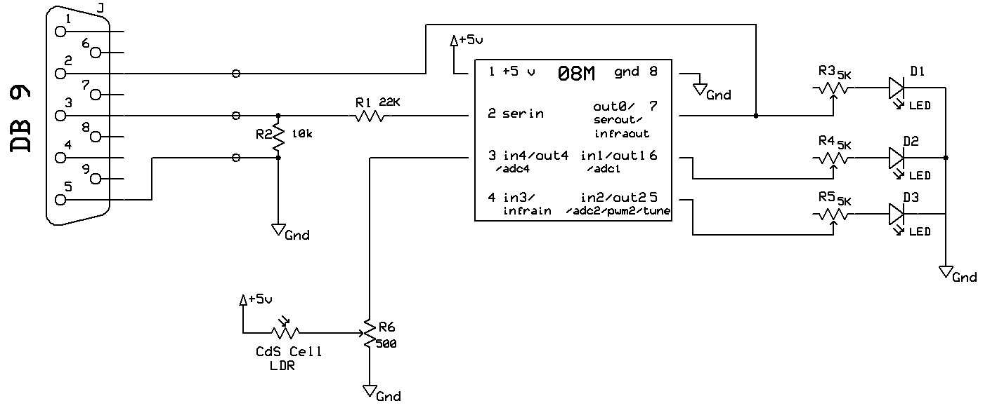
The real magic is in the software which is below. The code is well documented and should look familiar to those of you who have programmed PICAXE or PIC microcontrollers in BASIC.
| rem Reacts to light conditions - lights
on when dark / lights off when light rem All lights off & sleep mode if lights off for more than a few minutes to... rem react to overnight shutdown - wakes up again and restarts at first light rem d. bodnar 6-2-06 'w0-b01-w1-b23-w2-b45-w3-b67-w4-b89-w5-b1011-w6-b1213 symbol LED0 = 0 symbol LED1 = 1 symbol LED2 = 2 symbol led0on = bit0 symbol led1on = bit1 symbol led2on = bit2 symbol onFlag = bit3 '=1 if lights are on / =0 if off symbol flashcount = b1 symbol LDR = 4 symbol Counter = w1 symbol notused2 = w2 symbol LDRreading = w3 symbol notused3 = w5 symbol notused4 = w6 led0on=1:led1on=1:led2on=1 dirs=%00000110 'make pins 1 & 2 outputs for LEDs loop: readadc LDR, LDRreading pause 100 if LDRreading >=50 then skipahead: counter=counter+1 if counter > 3000 then OffForTheNight: '3000=5 minutes goto skipReset: skipahead: counter=0 skipReset: if LDRreading>=50 and onFlag = 1 then allOFF '>50=LIGHT if LDRreading<50 and onFlag = 0 then allON '<50=DARK if onFlag=0 then loop flashcount=flashcount+1 if flashcount<8 then loop toggle led1 flashcount=0 goto loop: allOFF: pins=%00000000 onFlag=0 goto loop: allON: pins=%00000111 onFlag=1 goto loop: OffForTheNight: pins=%00000000 high 2:pause 0:low 2:pause 100 readadc LDR, LDRreading if LDRreading <50 then OffForTheNight onFlag=0 goto loop: |
I hope that this article has started you thinking about ways to control
lighting and other aspects of your railroad. Please let me know if you
have any questions or ideas that you would like to explore in more detail.