|
The objective of this project is to design and construct a system that uses inexpensive lasers to detect the passage of a model train. Several different versions will be made. The simplest will use a single laser to activate a relay whenever the laser beam is broken. The circuit will require only a few parts: the laser, a phototransistor, two transistors, a relay and a few resistors. The other versions will include a PIC, PICAXE or Arduino microcontroller that will allow more sophisticated detection and operation. It is also important to stress that, even though this article deals specifically with model railroads, there are many, many applications for the detection systems described here in other areas. |
|
|
| Introduction I have used a number of train detection methods on both my garden railroad and my HO modular layout. All have advantages and disadvantages many of which are spelled out in great detail in articles on my web page (see "Sensors" at: http://www.trainelectronics.com/articles.htm ). Up until now my favorite way of detecting a train as it passes a point on my layout has been to use pulsed infrared sensors. These sensors use an infrared LED that is pulsed on and off at 38 KHz and an infrared detector that only reacts to pulses at that frequency. The emitter and detector are placed across the track from one another so that the beam of light is broken when a train passes. They are reliable and almost completely immune from interference from sunlight and other sources of light in the environment surrounding a garden railroad. Their primary disadvantages are
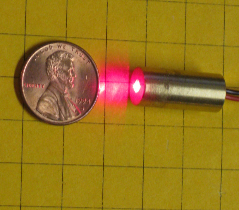
Recently I began experimenting with lasers and found that the circuitry needed to use them can be very simple and that their range can be quite impressive. Since their light is visible aiming & alignment are much easier. Up until now their main disadvantage was that you had to disassemble a laser pointer to acquire a small laser. Once you got the laser out of the laser pointer you still had to deal with the fact that most of these laser modules aren't designed for operation at 5 volts and that they frequently failed when put into continuous duty service. The need to cannibalize laser pointers disappeared when I found a vendor in China ( http://dx.com/p/genuine-new-wish-5mw-red-laser-module-5v-2-pack-10091 ) that could supply me with very small laser modules that are ideal for model railroad use. They contain a voltage regulator that allows them to function over a range of voltages from 3.5 to about 5 volts. More importantly, they are designed to run continuously, not just while someone pushes a button on a laser pointer.
The units are about 9mm (23/64") in diameter and 20mm (3/4") long. This makes them easy to hide on a layout. The distance that can separate the laser module from the sensor also allows for detecting a train while it occupies a large section of track rather than just when it crosses a point on the layout. This really simplifies how the sensors can be used and it really took care of a major sensing problem I was having with my modular HO layout. My module (see photo and http://www.trainelectronics.com/Module/ ) is 8 feet long and has a mining train that crosses the main line as it works its way up a mountain using switchbacks. When a main line train enters the module my mining locomotive needs to stop so that the two don't collide at the crossing! Before examining the diagrams below you may
want to view a YouTube video of the module in operation:
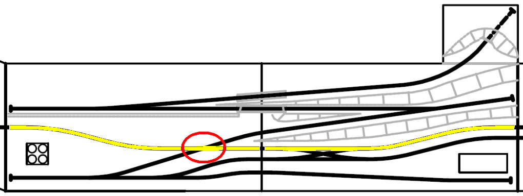
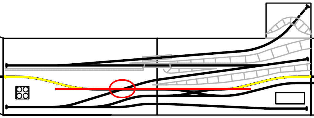
The troublesome crossing is circled in red in the drawing below. The main line is in yellow.
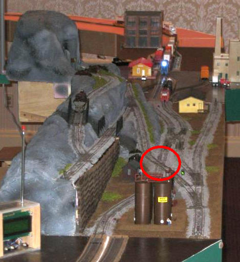
Here the same crossing is circled in a photo of the module. The computer controlled mining train goes up and down the mountain on a series of switchbacks while the main line (seen coming onto the module at the top) takes the low road.
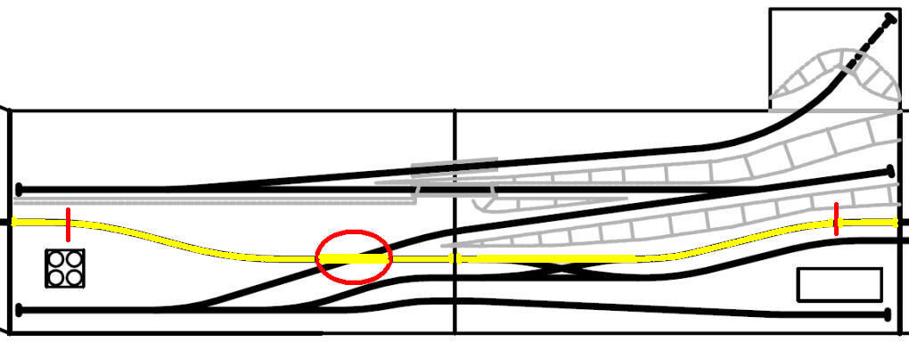
My first detection system used two laser sensors (shown as red lines in the drawing below), one at either end of the module. If one beam was broken the mining train would not enter the crossing until the beam at the other end was broken and then left unbroken for a number of seconds. This worked very well except for the times when two trains were close together on the main line or when the main line train hit one of the sensors and reversed its direction of travel before hitting the second sensor. If it went around the layout backwards and hit the sensor at the other end of the module the circuitry on the module thought the train had just passed and the mining train happily (and tragically!) entered the crossing in front of the on-coming train. This might have been A-OK with Gomez from the Munsters but others in the modular group were none too happy! (see: https://www.youtube.com/watch?v=HMxJtMoTnx8
Since we were using DCC (Digital Command Control - a computer-based method of operating trains that always has voltage on the track) I next considered using current detectors that sensed when a locomotive was on the track and drawing power. That might have worked were it not for the very long trains that we frequently run on the module. We had one running on the layout that had a locomotive, 50 coal cars and a caboose! Since the current detectors only detect cars (or locomotives) that are using power I would have had to modify many of the coal cars and the caboose so that a current would have been drawn when they were on the track. I had to find a better way as I didn't want to modify other railroader's trains to solve my problem. I settled on a laser detector that projected its beam across most of the main line track. Any time any train or part of a train broke the laser beam the mining train would be held back from the crossing. In the diagram below the long red line shows the path of the laser beam. It parallels the main line before and after the crossing and reliably detects a train approaching the crossing.
Advantages & Disadvantages of this System Advantages:
Disadvantages:
Two Different Ways to Use the Lasers The second implementation makes use of a microcontroller, a PIC 16F684, a PICAXE 14M2 or an Arduino, to activate the laser and detect if its beam has been broken. As you can imagine the use of the microcontroller allows a good bit more flexibility in setting up and using the laser. And, I was pleasantly surprised to discover, can control the laser's beam in such a way that it becomes virtually undetectable. The Basic Laser Sensor If you take a moment to look over the next schematic you will see that there isn't much to this design. The laser operates from the same 12 volt power supply as the rest of the circuit. The 220 ohm resistor, R5, in series with the laser's positive lead limits the amount of current that is available to the laser. The phototransistor, Q1, detects the presence of the laser light and, through transistor Q2, activates relay RLY1 and test LED, D3, which gives a visual indication of the laser being detected. Schematic:
The second schematic is almost identical except for the addition of another transistor that reverses the behavior of the relay. In the first circuit the relay pulls in when light is detected. In the second the relay pulls in when no laser light is detected and releases when the laser light is seen. The second circuit may be a better choice if you are running from batteries or some other low power source as it does not activate the relay's coil when the laser beam is unbroken, only on those less frequent occasions when a train passes.
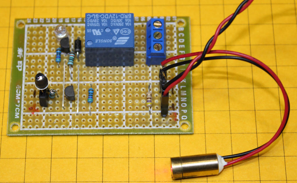
The prototype for this circuit was put together on a small piece of project board. The relay is at the top and the two transistor circuitry is to its left. The phototransistor is in the lower left. It has a small piece of heat shrink tubing over the lens to shield it from ambient light.
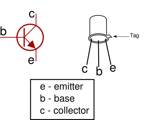
When connecting the phototransistor the emitter is closest to the tab. The middle lead, the base, is not used and can be clipped off.
|
Parts list for basic circuit
|

| Microcontroller Managed Lasers A microcontroller such as a Microchip PIC 16F684 can be used to make a much more sophisticated laser sensor than what was described above. Such a circuit will allow you to, for example, have the relay always stay on for a minimum of 5 seconds each time it is activated or only latch on after the laser beam has been broken for a set number of seconds or after a set number of beam-breaks. As you can see from the PIC schematic the microcontroller not only connects to the phototransistor, Q1, but it also controls the laser, D2, so that it can be turned on or off. The relay is triggered by pin 6 on the PIC through transistor Q2. LED D3 is an indicator and the switch connected to pin 3 is used for setting up the sensor. R5, shown as a 10K resistor, pulls the emitter of the photo transistor low and can be adjusted to make the circuit more or less sensitive. I have used a 22K resistor to make it much more sensitive to the pulsed laser beam. Schematic
Test Software This program simply turns on the laser and activates the relay and test LED if the beam is seen and turns them off if it is not.
|
Parts list for PIC version
|
|
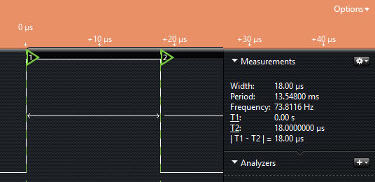
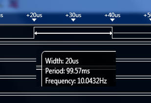
An Interesting Discovery I modified the software so that the laser would be turned on and left on for 0.1 seconds using a PAUSE 100 command. Then the program looks at the phototransistor, activates the relay and LED if it sees the laser and then turns the laser off for 0.4 seconds. This has the system check the laser twice each second with the laser only being on for two 1/10 second periods each second. The program worked well and the laser light pulses were less obvious as I had hoped but they were still clearly detectable. I wondered just how short a pulse the phototransistor and PIC could detect. I kept reducing the PAUSE statement until I got to PAUSE 1 (a pause of 1/1000 second) and everything still worked perfectly! Now each pulse only lasted one thousandth of a second and the laser beam was all but undetectable. Since I still had not yet found the "bottom" of the unit's sensitivity I switched from using the PAUSE statement, which works in 1/1000 of a second increments, to the PAUSEUS statement that works in 1/1000000 of a second steps. I was completely amazed when I started decreasing the PAUSEUS statement over and over testing every shorter pulses until I got to PAUSEUS 1 and it still worked! A bit of reading through the PICBASIC PRO manual told me that the pauses are really more like 10 or 20us because of the 16F684's clock speed. Nonetheless the pulses were so brief that even placing a piece of white paper directly in front of the laser in a darkened room barely made the beam detectable. To check the actual length of time that the laser was on I hooked the circuit up to my logic analyzer. This clip from the logic analyzer's screen confirms that one pulse lasts 20 us.
Pulsed Laser
Software |