Tilt-a-Whirl Train
Revised 03-20-07
The Idea
A recent impromptu meeting of some of the members of the Pittsburgh Garden Railway Society focused on ways that we might add interest to the train layouts that we set up for local train shows and other events. We also were looking for ways to involve more fellow garden railroaders in creating the displays. During the discussion one of the members recalled seeing a number of "gadget" railroad displays at a local grocery store. He described one that was an O gauge engine running on a circle of track that was on a set of bearings like a lazy Susan. The layout was tilted at an angle so that the train was going uphill all of the time. This created a sufficient back force on the track (remember Newton's third law?) to cause the entire layout to rotate under the almost stationary engine. We all thought this would be something that would catch the eye of visitors to our displays and, more importantly, could serve as a way to involve PGRS members in a creative activity.
First Test
I could see that there would be some significant design and engineering hurtles to overcome in translating this from the smaller O gauge layout to one that could operate with G scale trains.
The first of these was making the table. I had a box of 4' diameter track, the smallest that is commonly available, and thought that I could easily make a circular platform from a sheet of 1/2" plywood. Unfortunately a quick check of the 4' diameter circle of track showed that its maximum diameter was not 48", as implied, but closer to 52". It seems that the diameter of track is measured to the center of the ties, not to the outside as I had hoped!
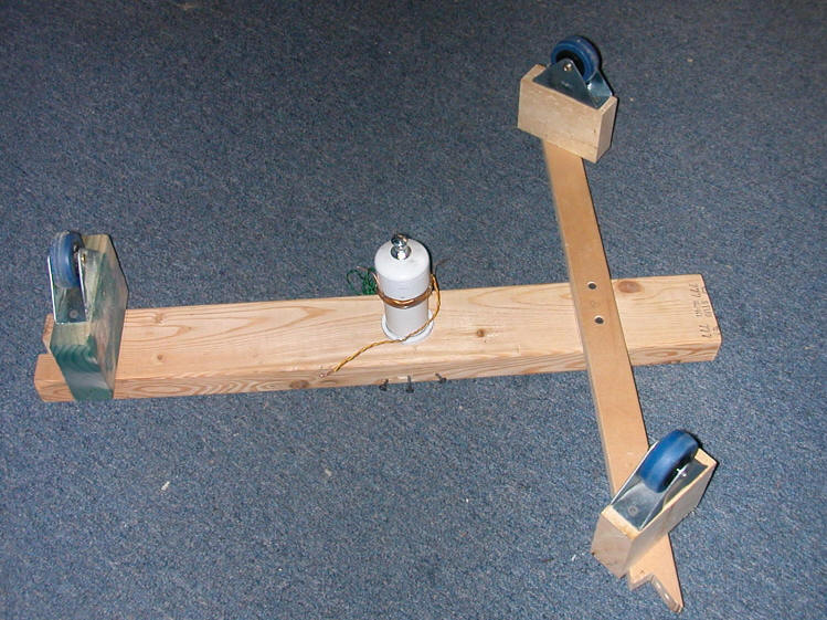
I had a little more than half of a sheet of 1/2" plywood that could be expanded to a 52" circle by adding extensions to the four edges. Not an ideal solution, but acceptable for testing. You will note in the photo below that care was taken to balance the weight of the added plywood so that the table would rotate evenly.
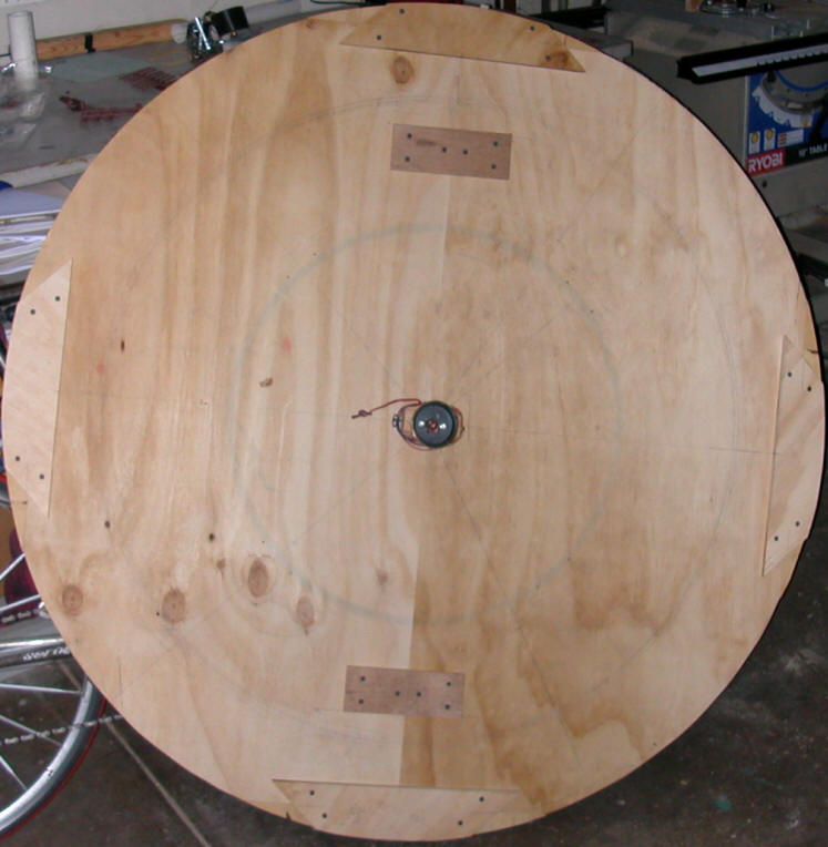
The next challenge was to create a rotating support that would allow the platform to turn with very little force. Since I am an avid cyclist my first thought was to use an old bicycle wheel as the bearings in their hubs are of very high quality and should be able to handle the weight of the table.
After a bit of cobbling to get it all to work the platform rotated nicely but there was so much force on the center mounting pin that the table wobbled a great deal, especially when track and an engine were added. The solution was to add a support to the outside edge of the table to take some of the strain off of the center support. A 7" wheel was added and the wobbling was reduced significantly. This wheel can be seen in the lower left corner of the photo below.
Once the table was reasonably stable a "proof of concept test" needed to be performed. Specifically, we needed to make a test to see if a small 1/24 scale engine could turn such a large and heavy platform. Adding track power to a rotating layout was sure to be no small trick so battery power was used for this test. Amazingly, the little 0-4-0 engine started the table spinning once it was elevated to about a 10 degree angle. Not bad for such a small engine that was dealing with a 17% grade.
Electrical Connection, Better Bearings and Less Wobble
The next challenge was providing power to the moving table so that the track could be used to power the engine. Although battery power worked well it was not practical for train shows where a layout could easily be running continuously for 8 to 10 hours.
I figured that I could use the central shaft from the bicycle wheel and its bearings as one power connection. The other could be fabricated from a ring of brass. Wrong! I quickly discovered that the high end Campagnolo bicycle bearings or their races or both were made of a non-conducting material, perhaps ceramic. No electrons flowed through the wheel no matter what I tried.
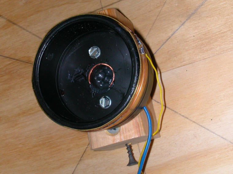
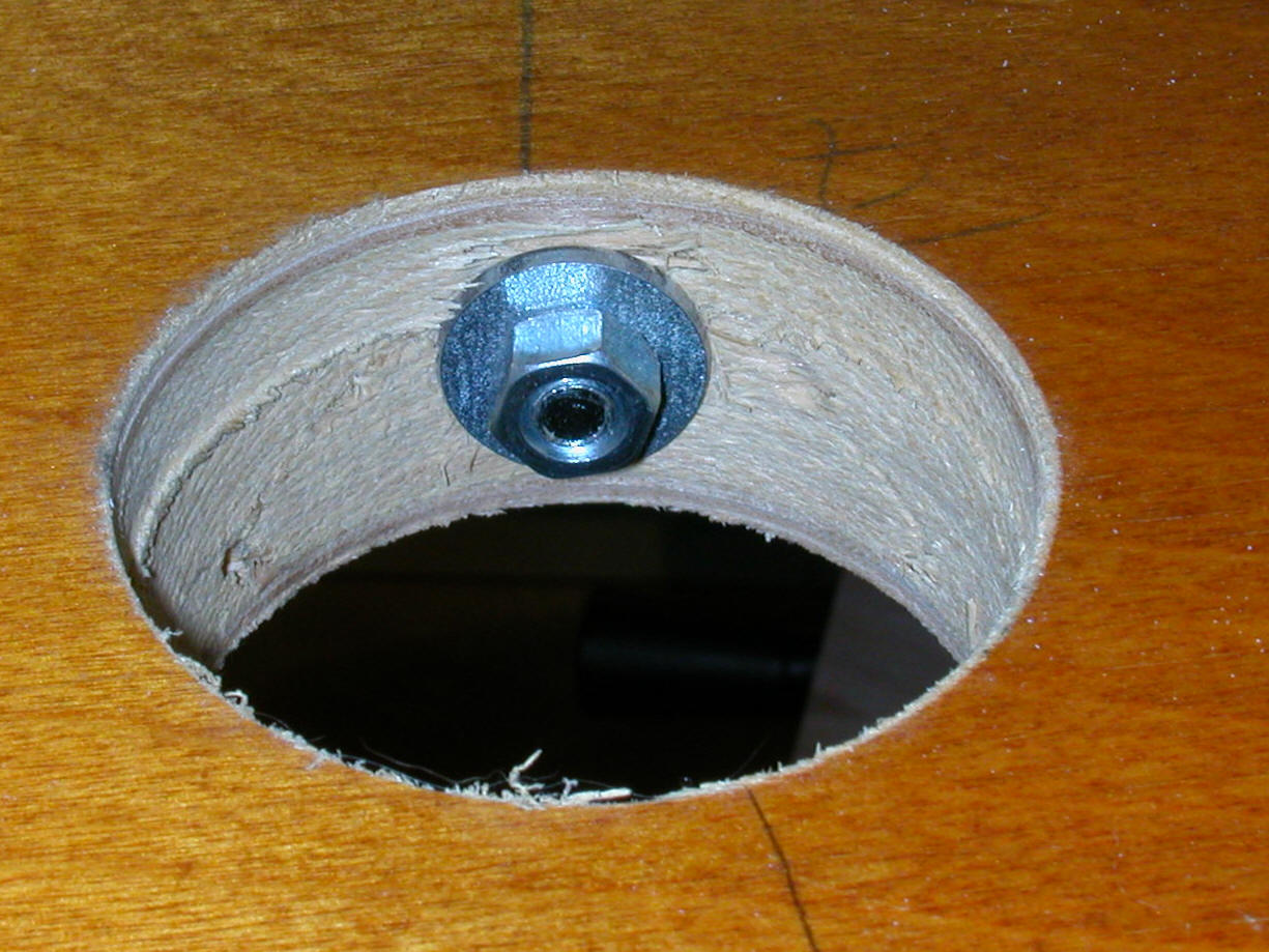
I was depending on getting power through the center support so it looked like a complete redesign of the bearing system was in order. The bicycle wheel was removed and replaced by a single support at the exact center of the platform. To insure electrical conductivity a 1/2" copper pipe end cap was attached to the center of the table. The center support on the stand was made of some plastic pipe which terminated in a 3" carriage bolt whose head fit neatly into the copper cap.
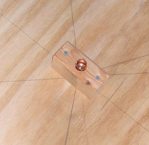
Here you can see the top of the carriage bolt extending from a plastic pipe cap.
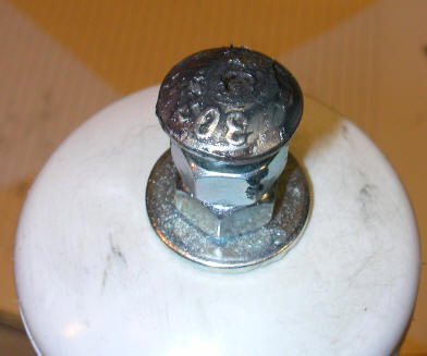
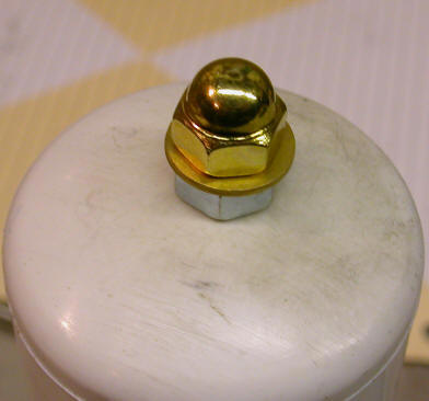
Although the bolt above worked well the brass plated acorn nut that replaced it worked even better!
This setup provided a reliable electrical connection and a low friction mount. To support the outer edges of the table three casters were added to the support system, evenly spaced 120 degrees apart.
The table continued to spin nicely and the wobble was almost gone.
The second electrical connection was made by mounting a 2 1/2" plastic pipe cap around the center support of the table. A brass ring was fabricated and attached to the outer edge of this larger cap. A set of three brass wipers was attached to the support system providing a second reliable connection.
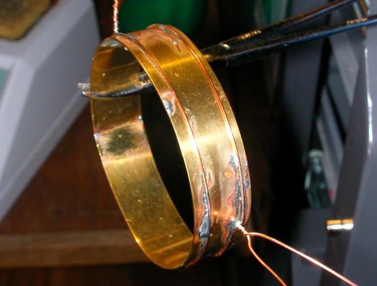
Here the brass ring has been attached to the end cap which is mounted around the 1/2" copper cap. The black substance in the middle is conductive grease.
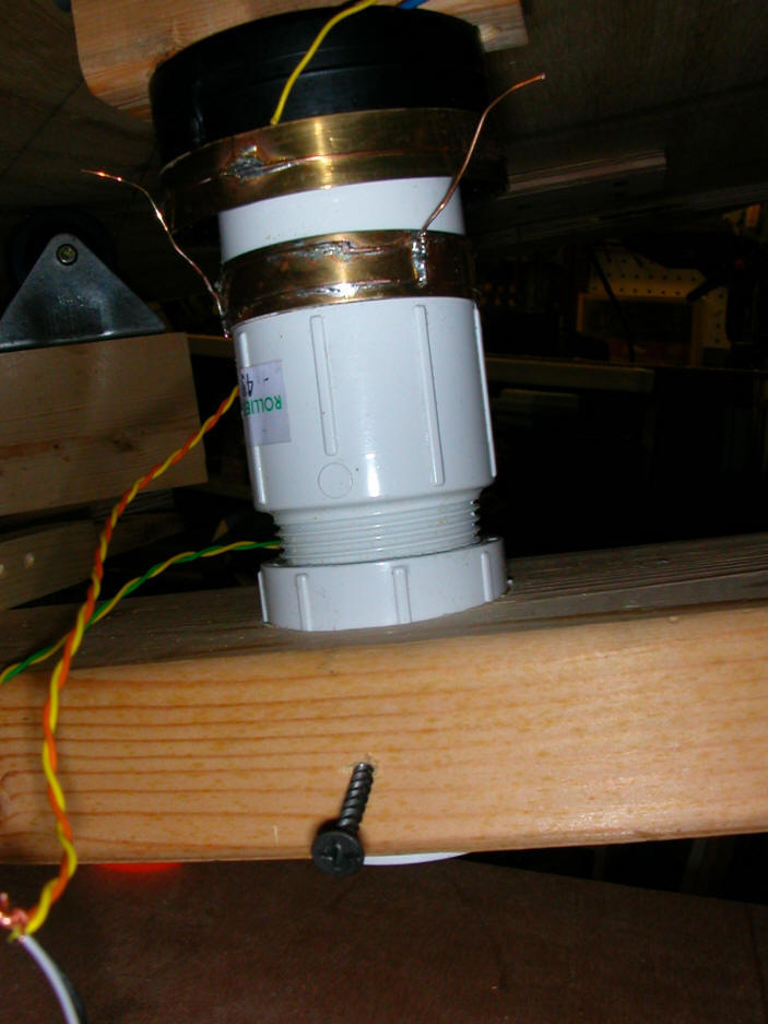
You can see the wire brushes below. They were eventually replaced with wider brass stock as the ones seen here bent easily. Also note the threaded section of plastic pipe. I discovered that the table spun best when just the center support pin and two of the three casters were contacting the table at any one time. The threaded section of the pipe allows for fine adjustments to the height of the center support providing three, not four, points of contact.
Lift Mechanism
The casters and center support point were attached to a plywood base with two sturdy door hinges. The allows the table to be tilted up or down to whatever angle was needed by placing blocks of wood under the main support beam.
Although this manual method of angle adjustment worked it just wasn't as elegant as I thought it should be. An electrically power lift mechanism was designed and installed next.
The lifting device is made up of a small geared motor that is similar to the one that I used in last year's incline system (see: Building a New Incline in Pittsburgh ). I knew that I would need lots of torque so I decided on using a long piece of threaded rod that would be rotated by the motor, which would be mounted on the movable table support. This rod would pass through two "T" nuts on the base and propel the rod, motor and table up or down depending on the way it was turned.
The biggest challenge was finding a way to attach the shaft from the motor to the threaded rod. While exploring at one of the world's great hardware stores (only 2 minutes from my home!) I stumbled on a package of threaded rod couplers. These are normally used to connect two sections of threaded rod by threading each rod 1/2 way into the coupler and locking each end in place with a nut.
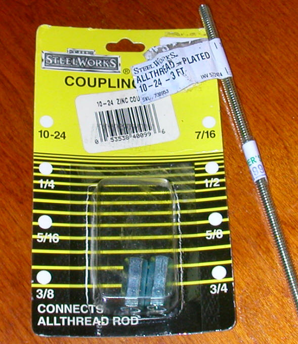
I found that the keyed shaft from the motor just about fit into the rod coupler. I drilled the coupler out just a bit and it fit perfectly. A hole was drilled through the coupler and the drive shaft and a pin was inserted to hold it fast. I used a fairly soft piece of metal for this pin so that it would shear off and allow the motor to spin safely should the mechanism bind.
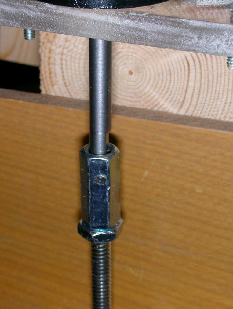
In this photo the motor is at the top. Its shaft goes into the drilled out coupler where it is fixed by the sheer pin that goes through the small hole in the coupler. The threaded rod screws into the bottom of the coupler and is locked in place by the nut.
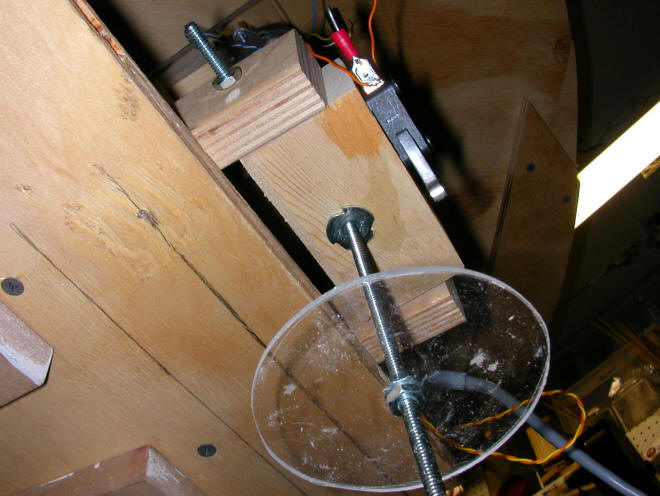
The motor was mounted onto a section of 1/4" thick Plexiglas and screwed to the movable base. The two "T" nuts were inserted into either side of a piece of lumber that was mounted so that it was free to rotate a bit. This would help to keep the rod from binding.
In this photo the motor and gearbox are at the top. The threaded rod goes through the "T" nut in the wood block. There is a loose "T" nut next to the one the rod goes through so that you can see its other side.
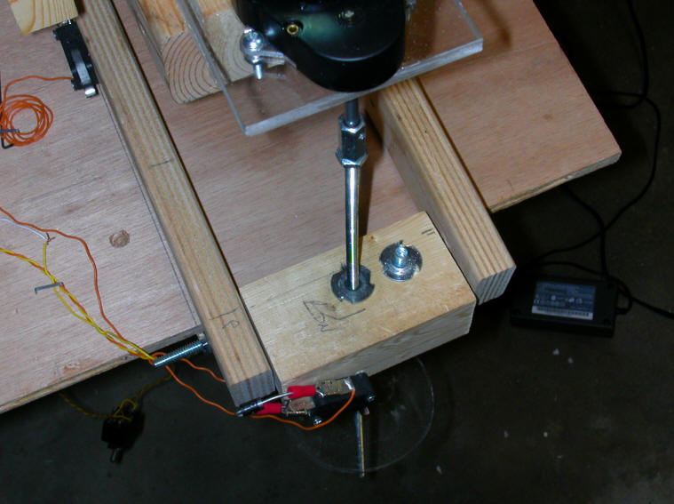
Note that this design mandates that the motor be mounted on the top as the threaded rod needs to have room to pass below the support system when the table is lowered completely.
Two limit switches were added to the lift mechanism so that the threaded rod would never be allowed to get to either of its ends. The circuit that was used is below. It uses two SPST switches and two diodes. The diodes allow the motor to be restarted once the DC polarity is switched. These diodes work just like the ones we frequently use on auto reverse systems. (see the articles on: Basic Auto Reverse Controller or Thermistors- The Magic Behind Smooth Acceleration for more information on auto reverse diodes)

The lower limit switch stops the motor when the platform is completely horizontal.
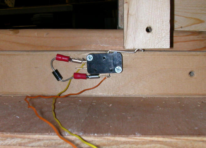
The upper limit switch trips when a plastic disk that rides on the threaded rod hits it. This disk can be moved up and down on the threaded rod to adjust the point of maximum tilt.
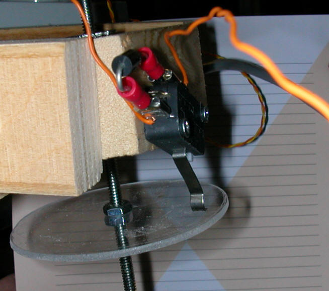
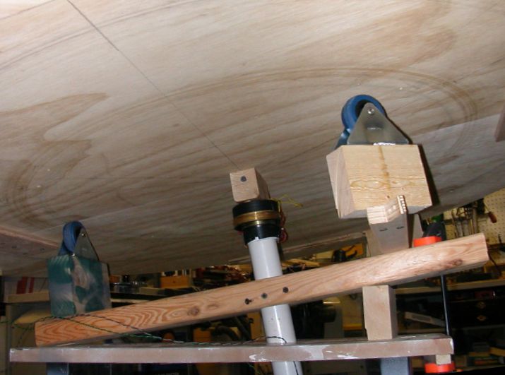
This photo gives a "looking up" view of the plastic disk and the upper limit switch.
Better Table
The project was just about complete but, as you can imagine, the thin 1/2" plywood platform began to develop a bit of a warp that made for rough running. I considered using 3/4" plywood or adding metal braces to the existing platform but didn't want to add any more weight to a platform that already weighed well over 25 pounds! I spent a number of days mulling over options that ranged from cannibalizing a round plastic garden table to fabricating one from fiberglass. Nothing I could come up with met my design criteria: It had to be light weight, strong, and inexpensive. As is the case with such things you can generally pick any two of the three but getting all of them in one package is no small trick!
Once I stopped focusing on finding a one-piece circle that measured at least 52" and thought about getting something half that size and connecting two pieces together I had the answer. Hollow core doors, found in many homes and offices, just might do the trick. There is a warehouse in Pittsburgh that collects and resells used building materials, Construction Junction. I remembered them having hundreds and hundreds of used doors. I didn't recall pricing but felt it was worth a visit. Two sturdy, light weight, 36" x 80" hollow core doors were found and the price was right, all of $5.00 each. Not only were they flat, light and inexpensive but they had a nice varnished finish on them as well.
Dissect a hollow core door and you will find that it is made up of a strong frame of 2" x 2" (or larger) lumber with a thin piece of plywood on each side. The hollow between the plywood pieces is strengthened by internal supports that are wood or fiberboard.
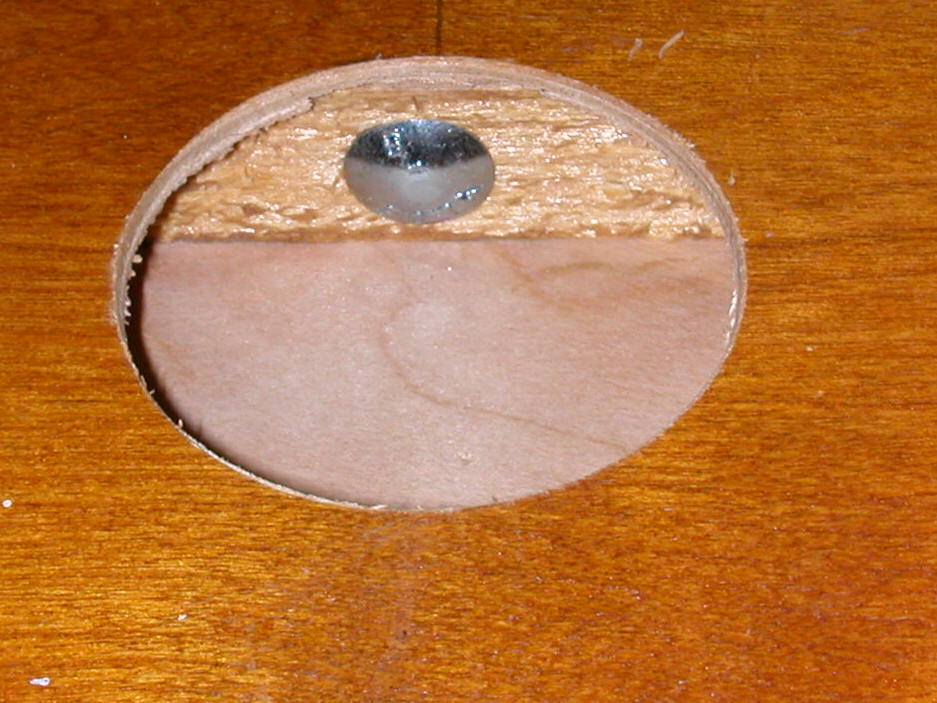
I reasoned that I could use carriage bolts to join the two doors together and cut a 52" circle from the joined doors. 3" holes were drilled on each door a few inches back from the edge. 3/8" holes, for carriage bolts, were carefully drilled into the edge of the doors so that the bolts would extend from the center of each edge. Since most doors of this type have an edge that is shaved a few degrees off of square to allow for a smooth entry into a door frame I took care to put one door "up" and the other "down" so that these tapered edges would match up giving a smooth, flat joint.
A nail and string were used to mark the outer diameter. Since I had some work to do to the edges before making a final cut I made the first circle about 54" in diameter. This also reminded me to cover my final cut line with masking tape to minimize splintering.
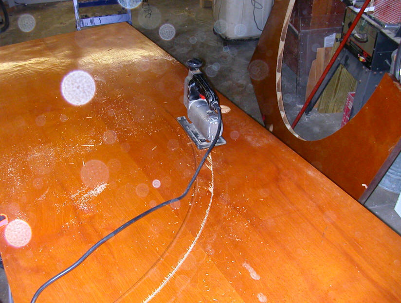
Much of the support system was removed from the doors when the outer part was cut off to make the circular cut. I filled in the open areas with expandable foam insulation. "Great Stuff" to say the least!
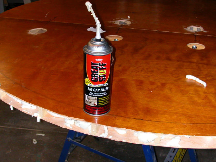
Once the foam had cured the edges were once again supported and the final cut was made to 52".
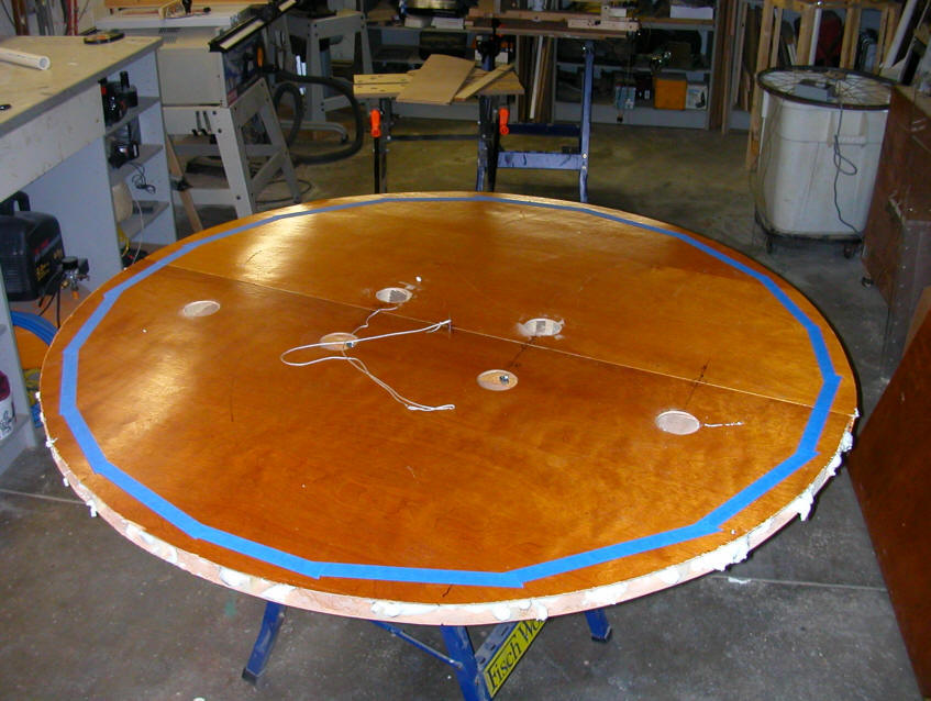
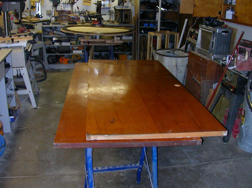
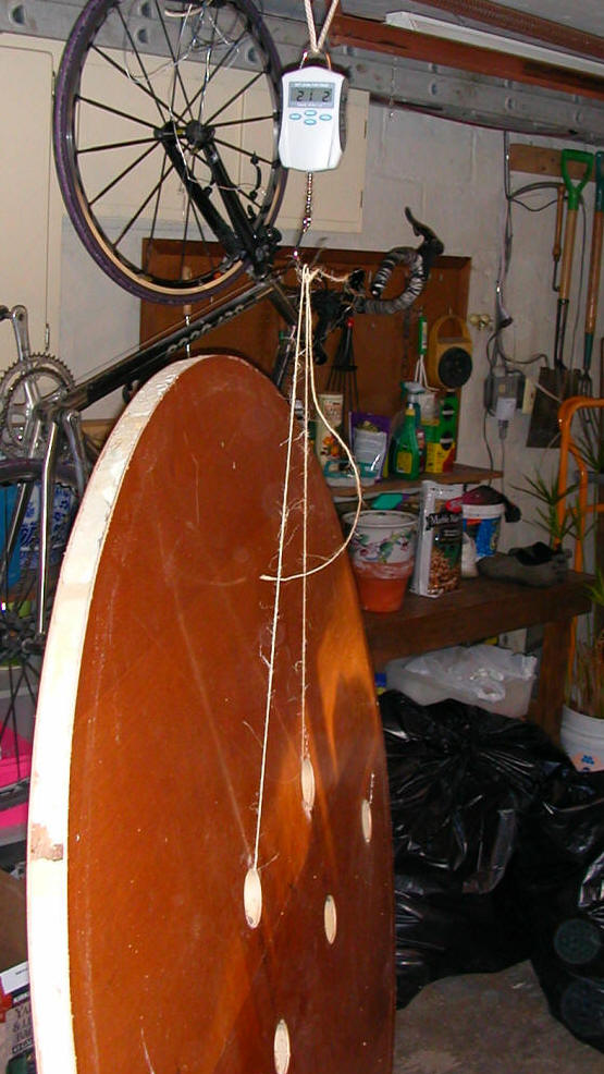
As you can see from the photo below the whole platform, without track, weighed in at a bit over 21 pounds. Lighter, stronger, flatter and less expensive than the plywood! Not a bad solution. You may also note that there are two additional 3" holes in the photo below. Originally I thought I would need four carriage bolts to join the two doors but two were all that I needed. The holes were drilled before I discovered this.
Operation
Initially the track power was supplied by a small LGB transformer. The motor for the tilt mechanism was manually turned on & off while the polarity was selected by a manual DPDT switch. In the final configuration a microcontroller based control unit was designed and made up that provided train speed and tilt angle adjustments by way of a standard TV remote control unit.
Scenery
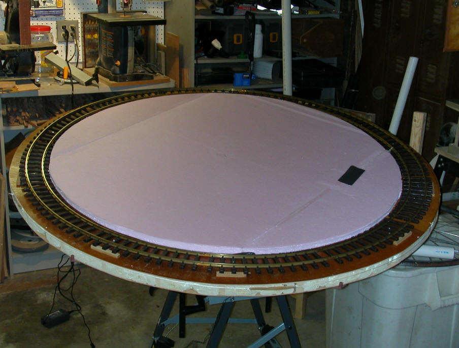
Rather than glue or fasten scenery directly to the table a simple method was devised that allows for quick and easy scenery changes. A 42" circle of 3/4" thick insulating foam fits nicely inside of the track which holds it in place. Multiple foam inserts can be made that will completely change the personality of the layout just by swapping them.
To test the feasibility of this idea I made a foam circle by gluing up a few scraps of insulation that I had in the shop. The circle could have been cut in one piece from a full sheet of foam. A pencil and a piece of string were again used to mark the circle which was cut with a utility knife.
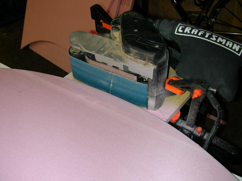
To dress up the edge a bit and to give it a small taper I clamped my belt sander to a support and moved the tilted circle of foam across the abrasive belt.
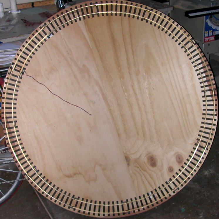
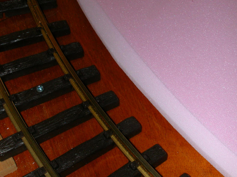
The tapered edge looks better and removes a high edge that could easily be hit by an engine or car as the train moves past. If you look carefully at the photo below you will also note that the track has been screwed down and that there is a small piece of wood under the outer edge of the ties. This banks he track to the inside just a bit and helps to keep the train on the track at steeper angles and higher speeds.
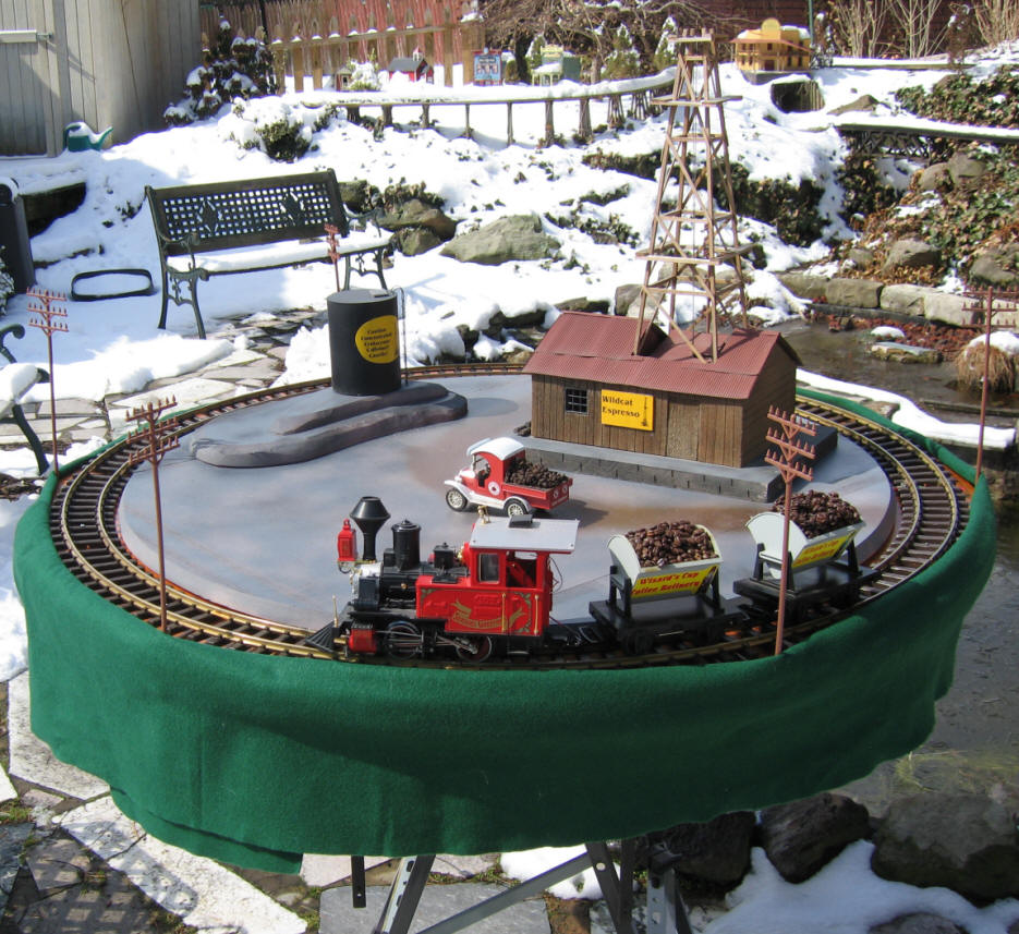
I wanted to keep the weight of the scenery to a minimum so that it would not keep the table from spinning easily so I borrowed a foam building that I had on my outdoor layout. This is an espresso well that goes along with the coffee mine that I have on my railway.
The well and accompanying storage tank add only a pound or two to the total weight. A small truck to transport some of the giant prehistoric coffee beans helps to balance the other items.
The only scenery that is likely to be used for all layouts is a set of Bachmann telephone poles that adorn the edges and a green felt "skirt" that dresses up the edge of the platform.
Other Scenery Ideas
The finished "Tilt-a-Whirl Train" was presented to the membership of the PGRS at a recent meeting. The group was pleased with its operation and lots of ideas for scenery were explored. These ranged from a circus train layout with a circus tent in the center to a dinosaur motif complete with a foam mountain and assorted prehistoric creatures. Several members expressed an interest in scratch building or bashing a "Barney Rubble Train" to accompany the dinosaurs.
Conclusion
I hope you have a chance to build your own tilting layout. It is sure to be a crowd pleaser and fun for the builders & decorators, to boot! Let me know how I can help.
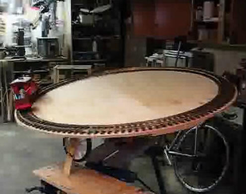
Right click the image below to play or loop.