[home]
MRC 6200 Repair
The MRC 6200 power supply utilizes a fairly simple circuit to
provide power for G scale and other scale trains. Unfortunately
shorting the track for even a short time can easily destroy one or both
of the NPN power transistors. The good news is that repair is not
difficult or expensive.
The following photos and text show how I was able to repair three 6200's
that failed.As with any project of this type note that you are
working inside of a case that contains 120 volt power. Even though
the wires are shielded please do not work on this power supply with the
power cord plugged into an electrical outlet and perform all tests with
the case on the unit. |
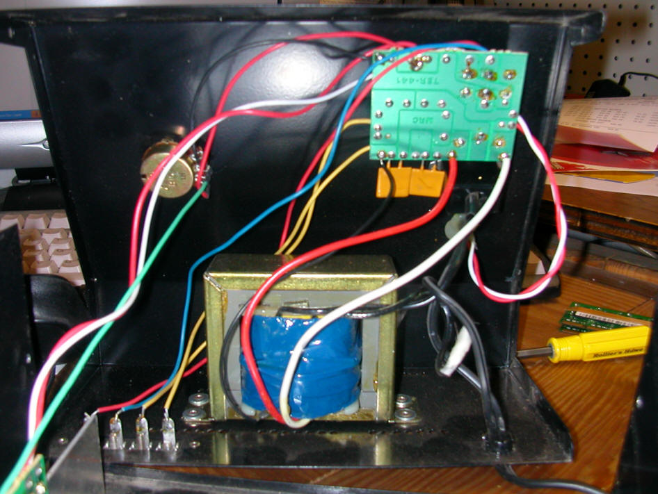
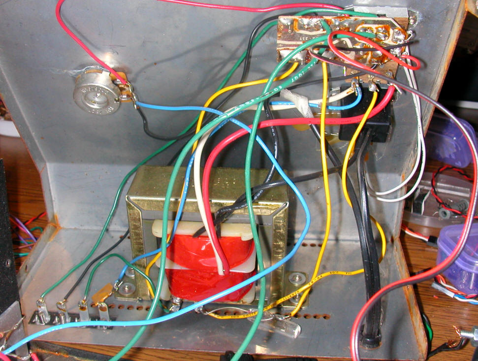
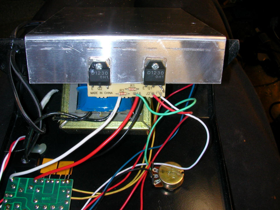
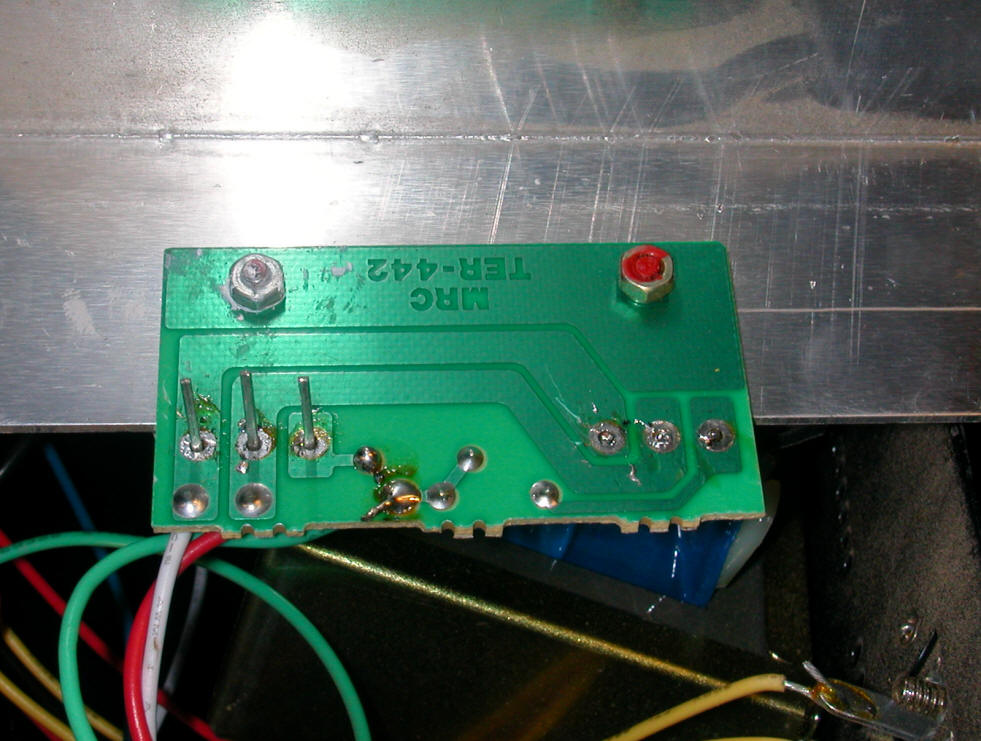
The power transformer is the blue object in the lower center of the photo.
The speed control potentiometer is in the upper left. The back of the
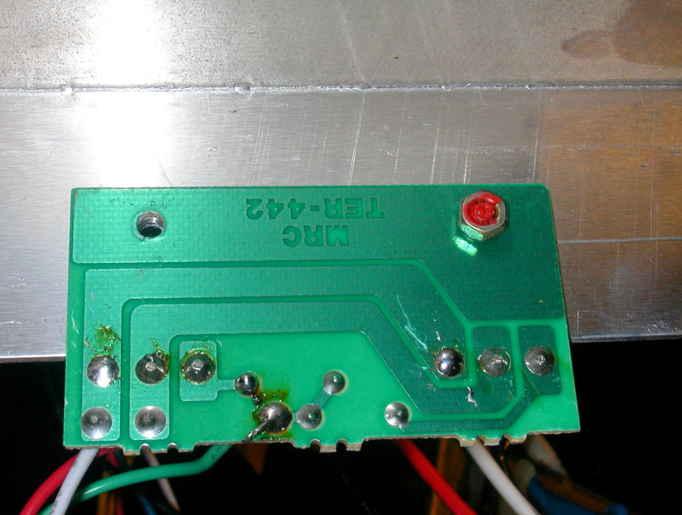
circuit board in the upper right is shown in the next photo.
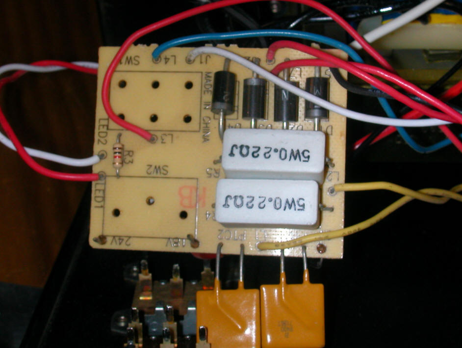
This circuit board contains the four diodes (upper right) that convert AC to DC
and two power resistors that are used to change the power mode.
The two D1230 NPN transistors are connected to a large aluminum heat sink.
They are wired in parallel. Most failures are with one or both of these
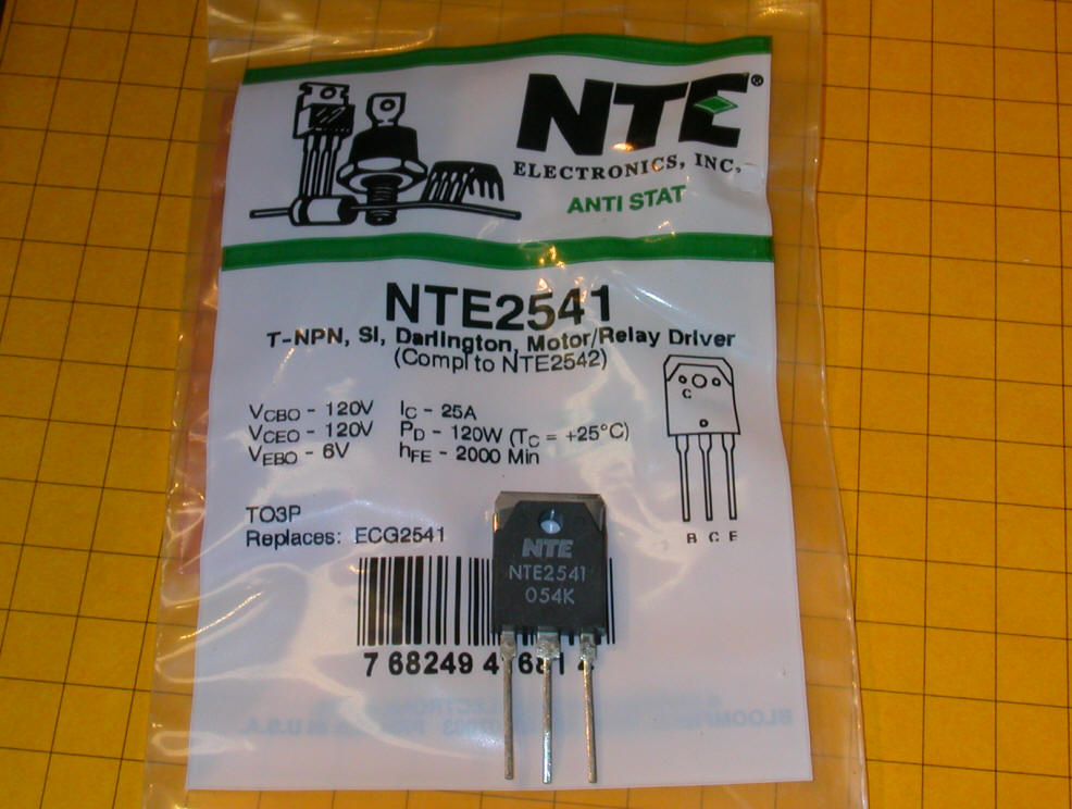
transistors. They are part #D1230 and are available from Mouser
(their part # is 526-NTE2541) for under $7.00. The two resistors (R1 and
R2) connect to the base leads of the transistors.
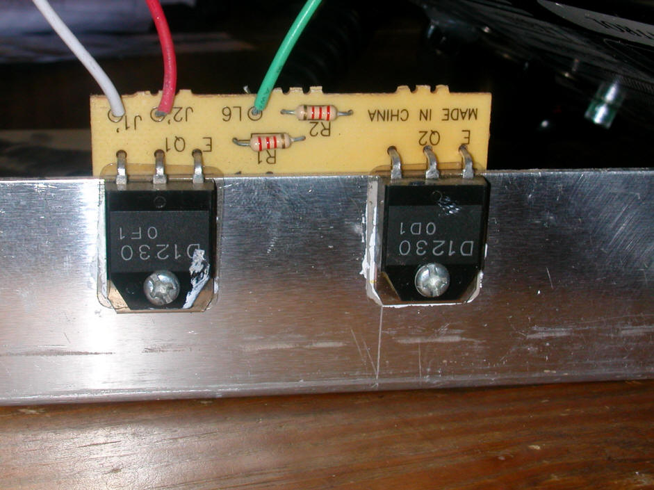
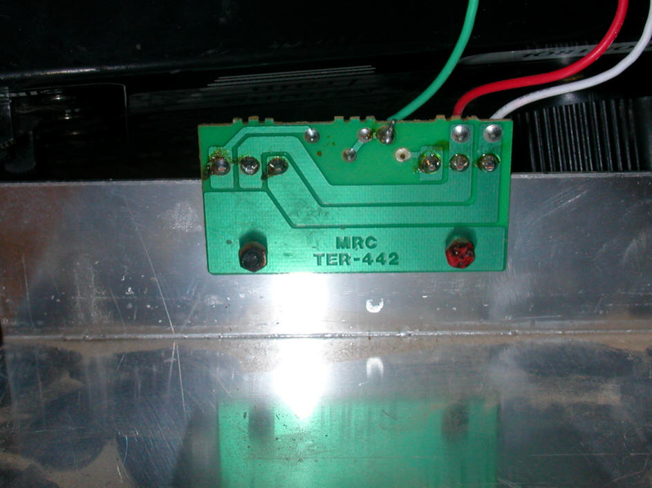
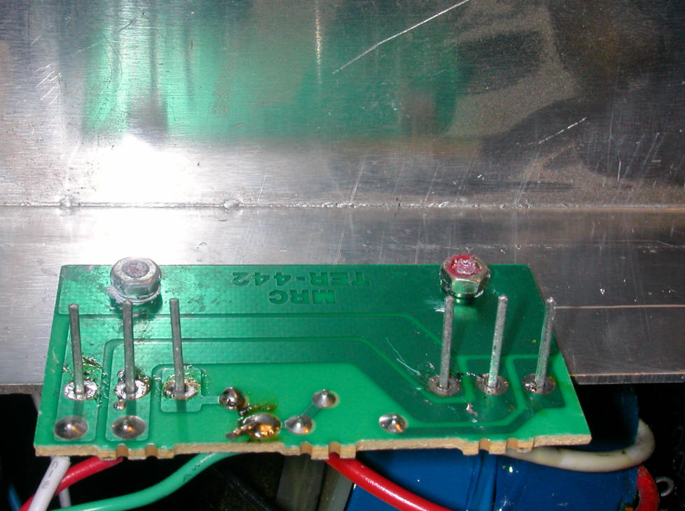
Here the back of the transistor circuit board is shown. Note that the two
D1230s are wired in parallel.
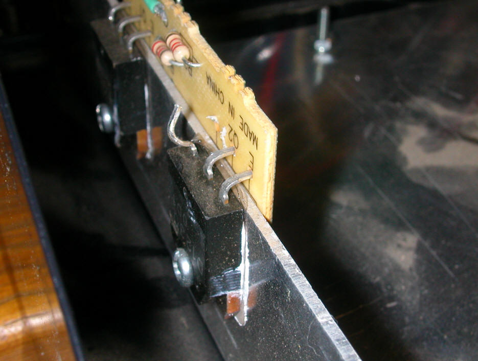
You can make a temporary repair by unsoldering and lifting the emitter of one of
the transistors. If you are lucky the power supply will work but with a reduced
power capacity. If you disconnected the lead of the good transistor (50-50
chance!) put it back on and disconnect the emitter from the other one. In
this photo the emitter has been pulled. Note that the lead marked E
is the base of the transistor and that the collector is the center lead which
connects to the case and the heat sink. Since the collector connects to
the case pulling its lead will not disconnect it from the circuit.
Additional repair notes added 10-31-07
There are two versions of the MRC 6200. The older unit has a silver case
and the newer one has a black case.
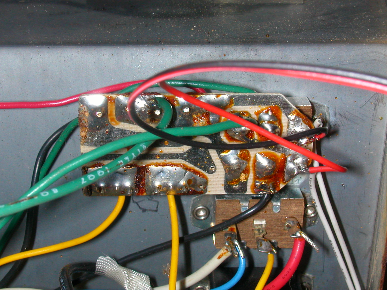
When compared with the orderly circuit board and wiring inside of the black case
units the silver are a maze of wire and "dead bug" construction.
This is the back of the circuit board that has the four diodes.
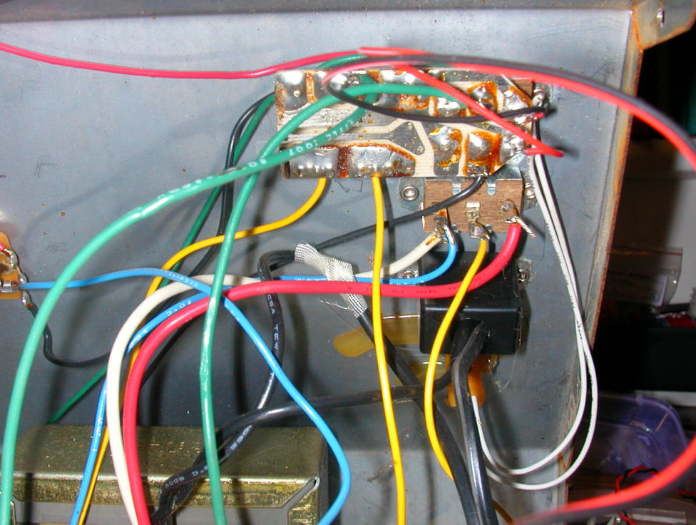
Here is a close-up of the same board.
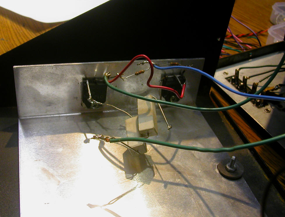
This view shows the two power transistors as they were wired when the case was
opened. I am not sure if this is the normal factory installation as
several of these units were repaired before I got them. Note that the
emitter of the right transistor has been disconnected from the resistor.
This was a temporary fix before the repair parts arrived.
Here the replacement transistors have been installed. Note the generous
coating of heat sink grease between the transistors and the aluminum heat sink.
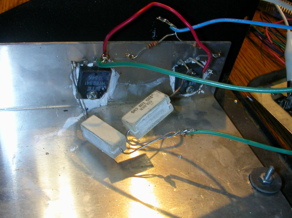
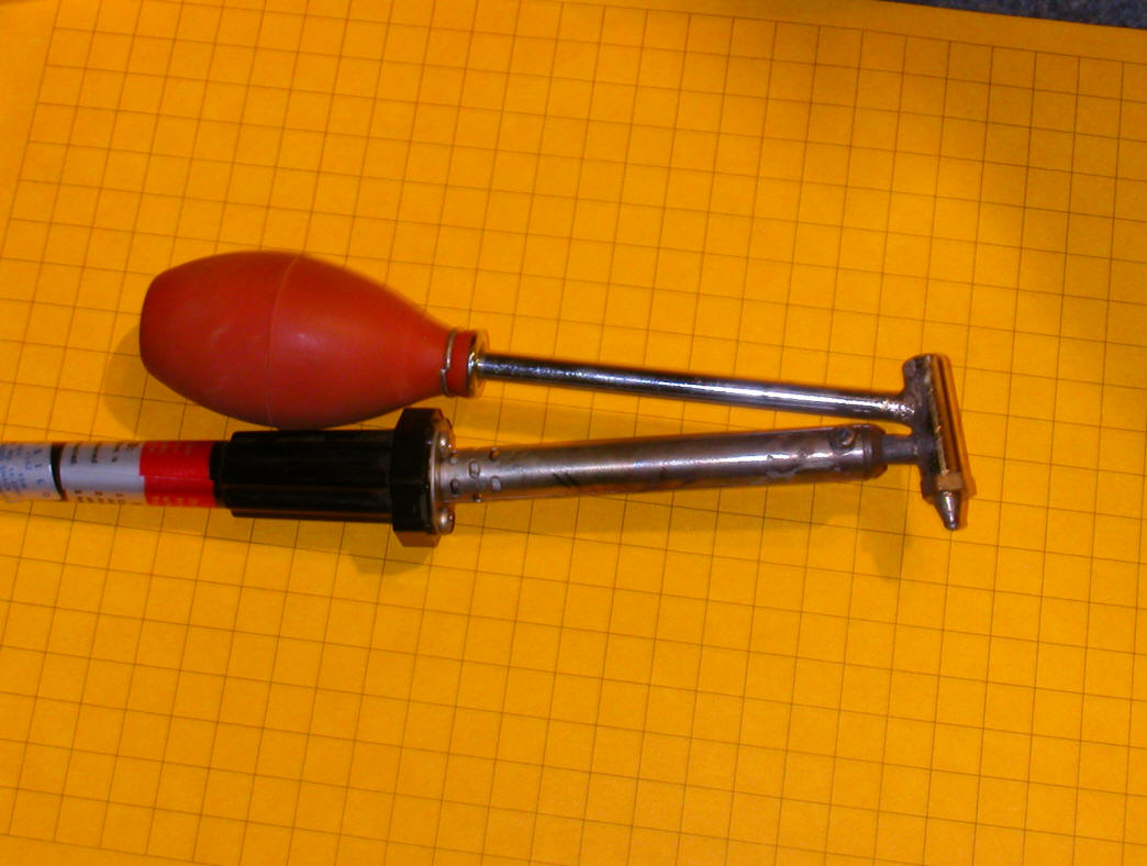
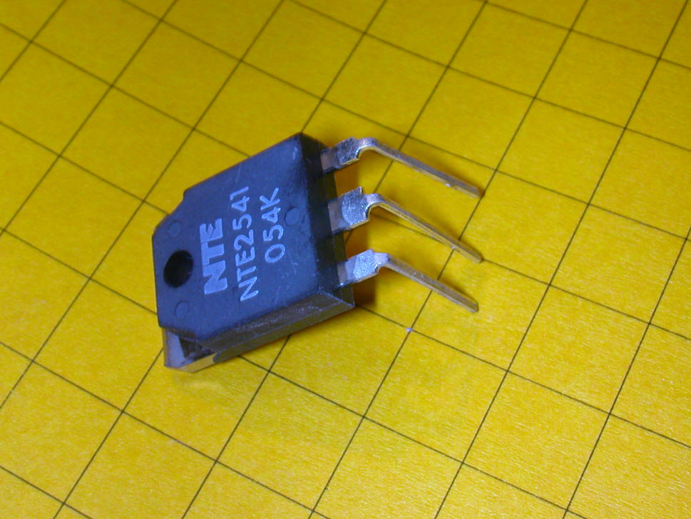
The transistors that were used for the repair were from Mouser and came in the
package show below.
Repairing the newer black cased units is quite a bit different from what is
shown above as the transistors are mounted on a circuit board.
Here the heat sink has been removed from the bottom of the case so that the
transistors and their circuit board can be seen clearly. Note that one
lead of the right hand transistor has been removed, again this was a temporary
fix.
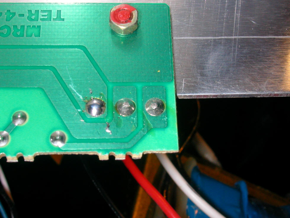
This is the back of the board. Note that one screw has been removed so
that one transistor can be removed at a time.
In order to remove the transistor a solder sucker was used to remove most of the
solder.
Here are the leads before solder sucking them.
Here they are after using the solder sucker. The leads on the new
transistor have been inserted in the holes on the left.
I found it much easier to insert the transistors if I preformed the leads like
this:
Both sets of leads are inserted and the screws are back in ready for solder.
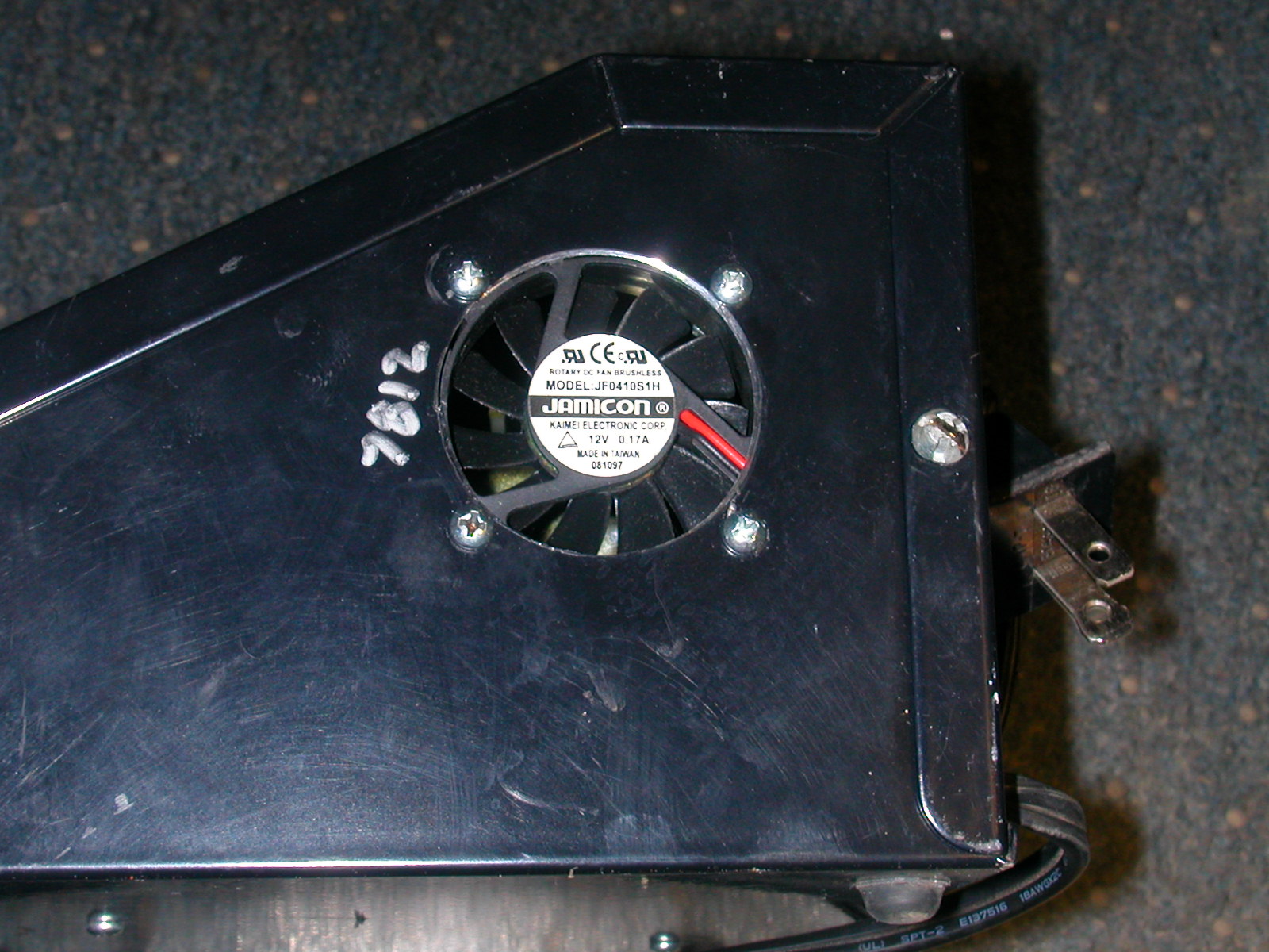
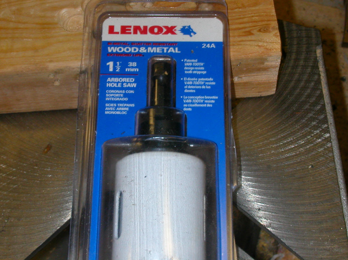
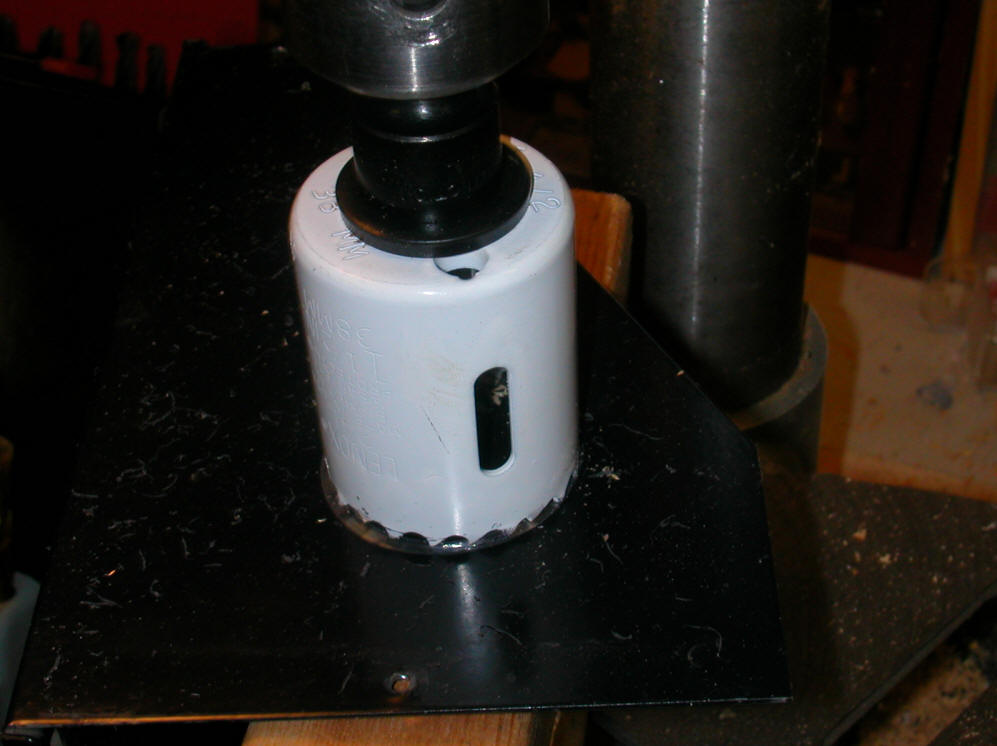
One final suggestion - add a fan
I added a small computer muffin fan like the ones once used to cool CPUs.
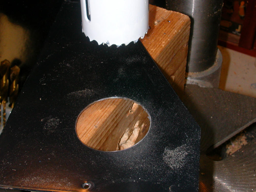
The hole I needed was 1 1/2 inches in diameter. I used a metal cutting
hole saw.
In a drill press.
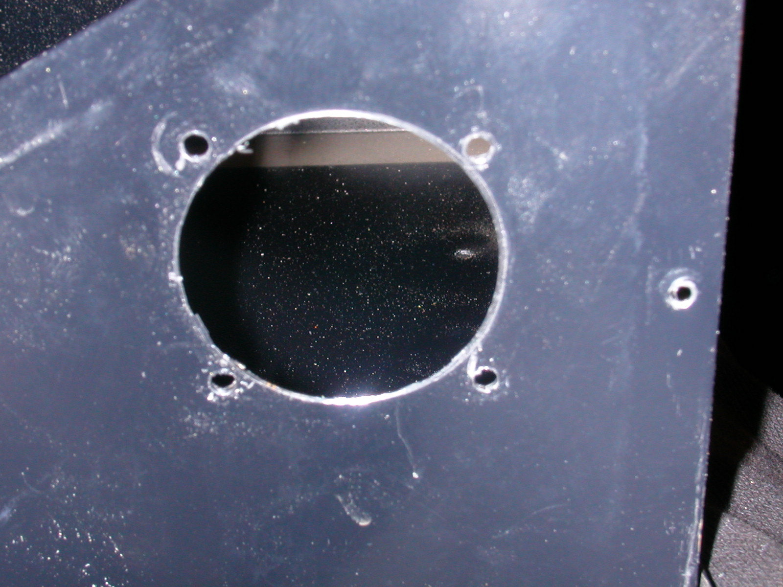
Four additional holes were added to bolt the fan in.
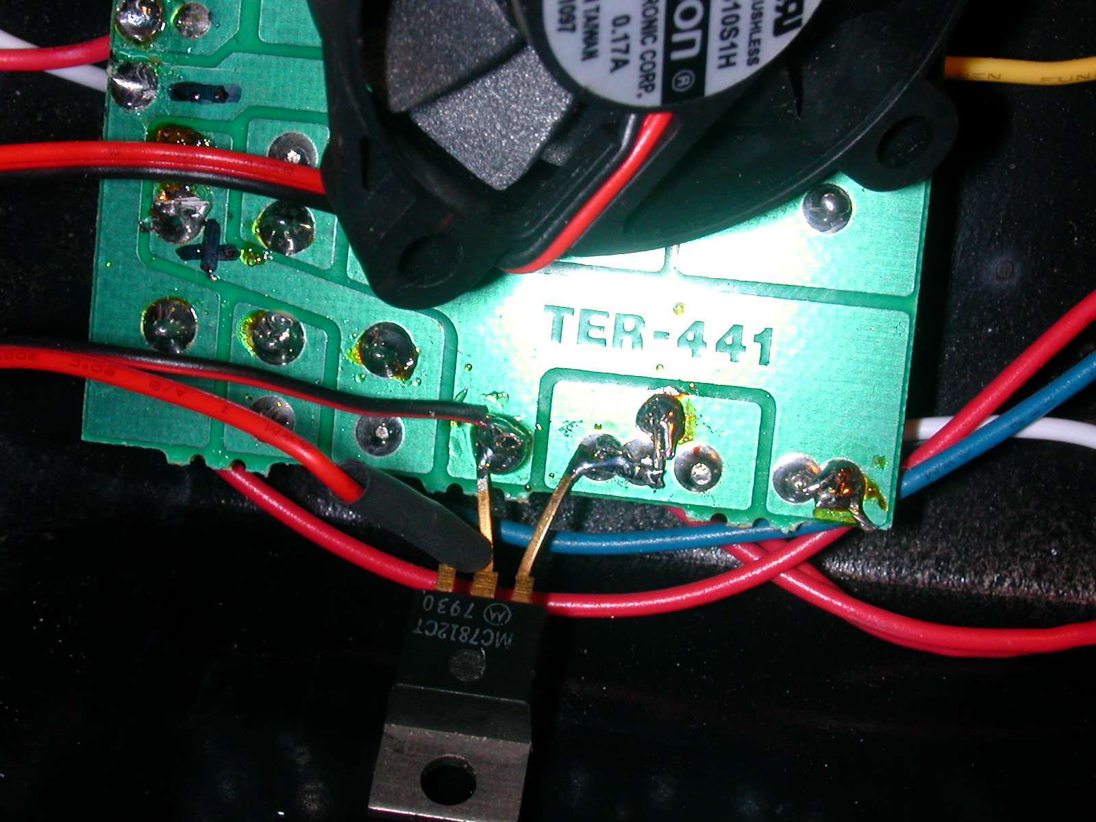
Power for the fan was taken from the "reservoir" section of the
power supply. The voltage at this location is a constant 20 volts or so.
I used a 7812 voltage regulator to reduce the voltage as the fan is rated at 12
volts.
The input pin of the 7812 is the pin on its right in this photo.
It goes to the positive terminal below. The center terminal goes to the
negative terminal. The fan's positive lead goes to the 7812's output and
the fan's negative lead goes to ground. Note the heat shrink tubing
insulating the output of the regulator.
Here is a broader view of the board. After I soldered the
leads I insulated the regulator's tab with tape as it is grounded and it
wouldn't do to have it rubbing something it shouldn't!
.JPG)
Done!