[home]
MRC DCC Decoder
#AD322
revised 11-22-08 d. bodnar
Click Here for Relay Installation Notes
| The AD322 is an 8 amp G-Scale DCC decoder.
The notes below may be of benefit to owners who wish to understand or
repurpose ("hack") the decoder. It has a rather full set of
functions that could easily be repurposed for a number of other
projects.
One modification that comes to mind is to add two
reed switches so that magnets on the track can trigger the bell and/or
horn. This would be valuable for those who don't have those
functions on their DCC Controller.
Note that these are preliminary
observations and are likely to be revised. |
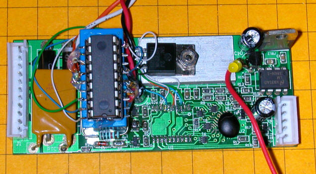
The image below shows the top side of the AD322
board.
(click on the image below to see a larger version)
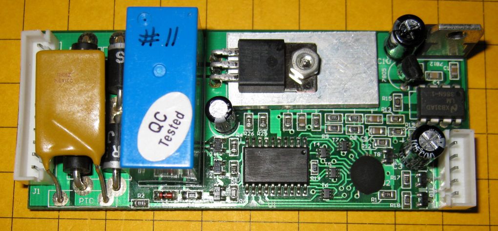
From left to right significant components are:
-
white 11 pin connector for track power, motor,
lights
-
polyfuse (mustard colored item) - works like a
resettable fuse
-
4 diodes (black items under polyfuse)
-
DPDT (double pole / double throw) relay -
determines direction
-
black power transistor on silver heat sink
-
20 pin black object - microcontroller - the ID
has been sanded off but it is probably a PIC 16C717 or similar
-
round black blob is the sound control unit
-
tiny items surrounding sound blob are
optoisolators and/or transistors that activate sound and light functions
-
tabbed unit in upper right 7812 voltage
regulator for amplifier
-
smaller black 3 pin device below 7805 voltage
regulator for microcontroller
-
8 pin device right center audio amplifier LM386
-
white 5 pin connector for speaker and strobe &
ditch lights
Microcontroller Pins:
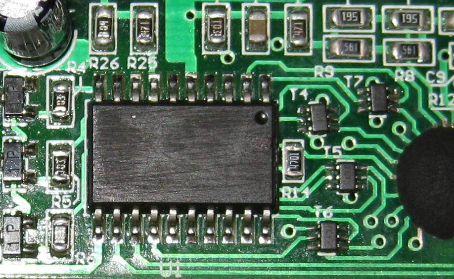
By testing each pin with an oscilloscope I gleaned
the following by cycling through various functions on the board. Note that pin 1
is in the upper right corner in the photo - next to the small round dimple.
Pins are counted 1-10 from right to left for the top row and 11-20 from left to
right across the bottom.
| Pin |
Function |
Comments |
Pin |
Function |
Comments |
| 1 |
Coupler sound |
|
11 |
DCC signal in |
from bridge rectifier section |
| 2 |
Bell sound |
|
12 |
long horn - starts ditch lights |
these could be reversed |
| 3 |
short horn |
|
13 |
starts strobe |
these could be reversed |
| 4 |
long horn |
|
14 |
other audio functions |
diesel start up sound |
| 5 |
+ 5 volts |
power |
15 |
other audio functions? |
|
| 6 |
other audio functions |
|
16 |
GND |
negative power connection |
| 7 |
PWM pulses |
goes to power transistor |
17 |
other audio functions? |
|
| 8 |
relay |
determines direction |
18 |
other audio functions? |
|
| 9 |
reverse light |
|
19 |
other audio functions? |
|
| 10 |
forward light |
|
20 |
other audio functions |
diesel motor idle sound |
Sound Modification
Pins 1, 2, 3 and 4 are used to activate the sounds shown in the table above.
If we lift these pins from the circuit board we can solder in wires that will
allow us to trigger sounds with reed or other switches.
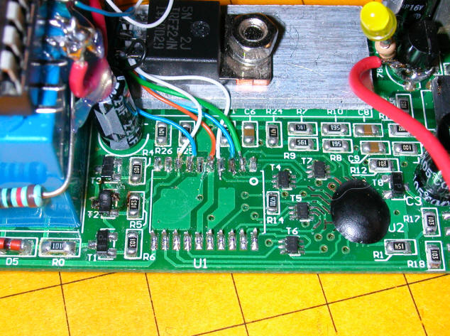
In the photo below pins 1 through 4 have been lifted from the board and four
wires (orange, red, white and blue) have been soldered to the pads that they had
been connected to. If we pull each of these wires low with a 10K resistor
we can trigger a sound by pulling the wire high with 5 volts (through a 1K
resistor)
.JPG)
The schematic shows that pins 1-4 have been lifted. A 10K resistor
connects each of the pads to which the pins were soldered to ground. A SPST
momentary switch connects each pad to +5 volts through a 1K resistor. The
1K resistor is probably not necessary but limits the amount of current that can
get to the sound circuitry.
Installing a PIC Microcontroller
The microcontroller that is factory installed in the decoder can easily be
removed and replaced by your own PIC microcontroller. This will allow you
to have the components of the decoder operate as you like. Reprogramming
the PIC to respond to DCC commands is not the intent of this modification.
The objective is to use the microcontroller to control the speed and direction
of the motor and to operate the bell, short whistle and long whistle sounds.
A PIC 16F88 was installed for this project.
The first step is to remove the existing microcontroller. This is easily
done by snipping the leads of the device with a small set of side cutters.
Once this is done the microcontroller can be lifted from the board and
discarded.
The new PIC microcontroller is significantly larger than the surface mount unit
that was removed. The best place to mount it is atop the relay box.
An 18 pin socket, with its pins splayed to the side, was hot melt glued to the
top of the relay and very thin, 28 gauge wire was used for connections.
The connections to the PIC include + 5 volts and ground to pins 15 and 5,
respectively. There are also four wires that come off of the PIC that are
used for ICSP (In Circuit Serial Programming) which allows you to reprogram the
chip while it is installed rather than removing it and placing it in a
programmer each time the software changes. This is really a significant
time saver.
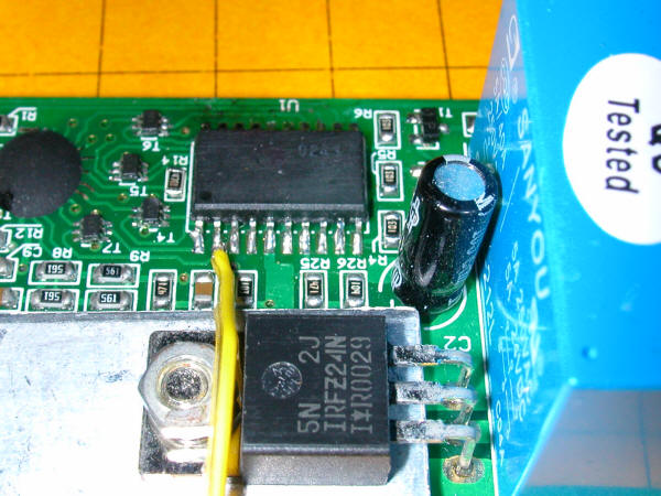
In this photo you can see the spot where the original microcontroller once
resided and the new PIC atop the blue relay.
The green, blue and white wires to the right connect the short horn, long horn
and bell to the new PIC. The white and blue wires to the left connect the
relay and power transistor to the PIC.
The sounds and relay are controlled by simply having the PIC pull the
appropriate pin high (setting to +5 volts) or low (setting to ground). The
power transistor controls the speed of the motor when pulses (Pulsed Width
Modulation) are applied to the base of the power transistor. The more "on"
the PWM pulses are the faster the motor spins.
Relay Installation Notes
For those of you who would like to activate an external relay with one of the
decoder's functions, to turn on a smoke generator, perhaps, here are step by
step instructions.
Parts:
1 - relay - I used a 12 volt SPDT relay
1 - 2N2222 NPN transistor (any NPN switching transistor should work)
1 - 1 amp diode (any silicon diode will do)
1 - 1000 ohm resistor
hookup wire
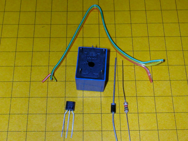
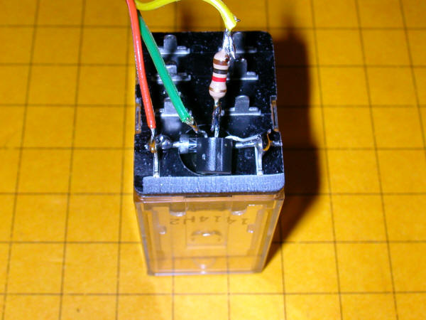
Solder the diode between the two coil leads.
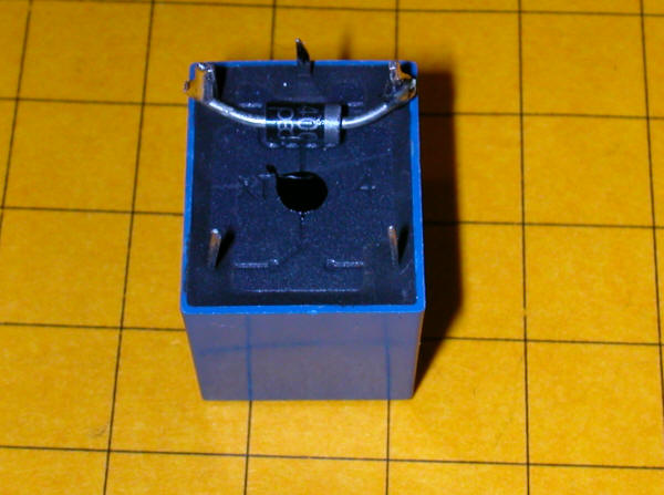
Align the transistor as shown and solder the collector to the coil connection
that is NOT on the banded end of the diode.
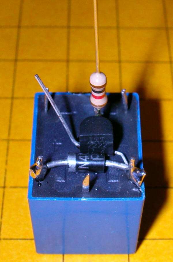
Bend the base and emitter leads up as shown.
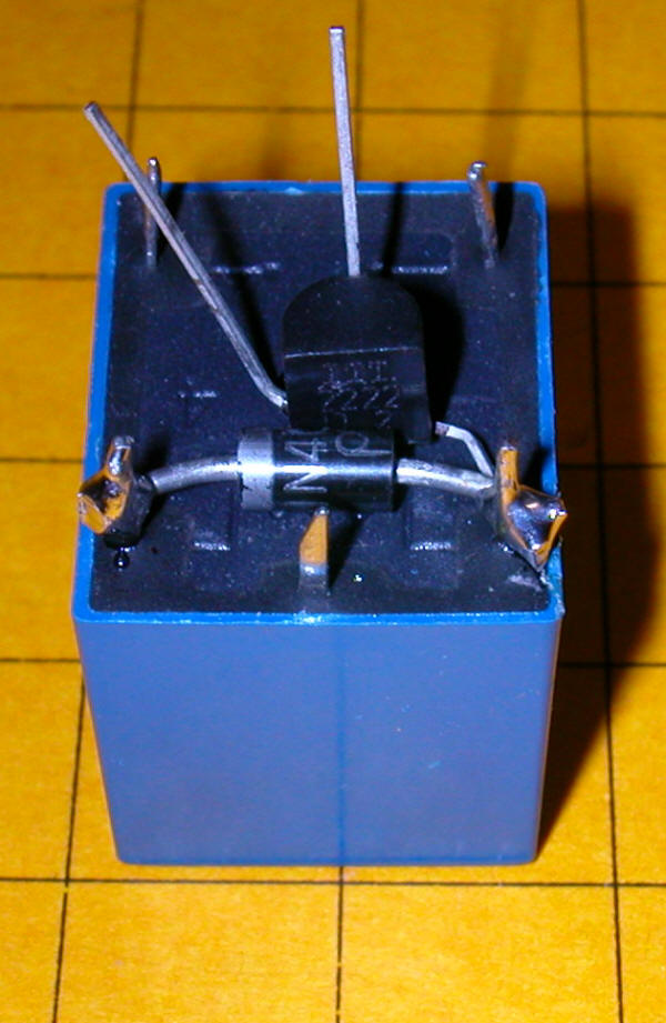
Solder the 1 K resistor to the base lead - shorten both the base and resistor
leads before soldering
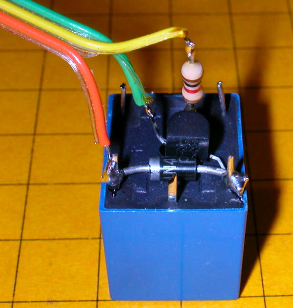
Solder the green wire to the emitter of the transistor, the red wire to the coil
connection that goes to the banded end of the diode and the yellow wire to the
resistor.
|
TESTING 1 2 3
At this point you can test your wiring. Connect the orange wire to a
source of positive 12 volts (a 9 volt battery should work for most relays).
Connect the green wire to the negative terminal of the battery or power supply.
Touch the yellow wire to the positive terminal or to the orange wire and the
relay should click as it pulls in. Disconnect the yellow wire and the
relay should turn off. |
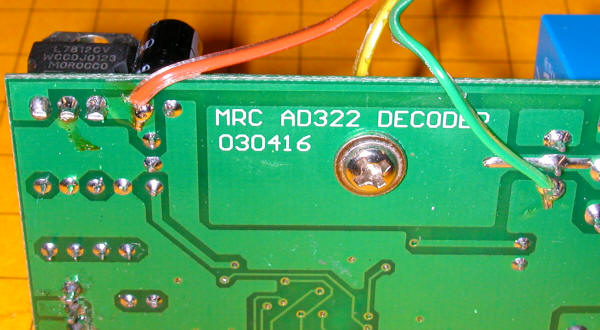
Decoder Wiring
We need 12 volts to operate the relay - the 7812 voltage regulator on the
decoder is shown here.
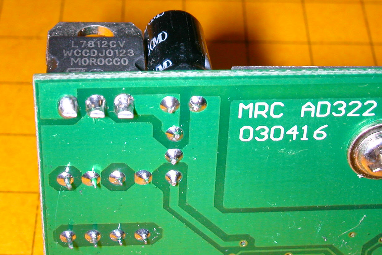
The orange lead gets 12 volts from the contact shown at the left. Ground
is easily picked up with the green lead on the right.
Now comes the fun part, soldering to the surface mount microcontroller's pin #2.
Strip and tin the end of the yellow wire. Shorten the exposed wire to
1/16". Carefully solder it to the #2 pin as shown. Check for solder
bridges with a high powered magnifying glass.
When you are done turning the bell sound on will activate the relay and turning
the bell off will release the relay. Note that the bell latches on or off
. You can use pin 1, coupler clank sound, if you only need a momentary
activation of the relay each time you do the clank sound.
Here is a different 12 volt relay with the same wiring. Note that the
2N2222 is bent over the diode but that the leads are wired in the same way.