|
Kit Construction - Part 1 - Main Circuit Board |
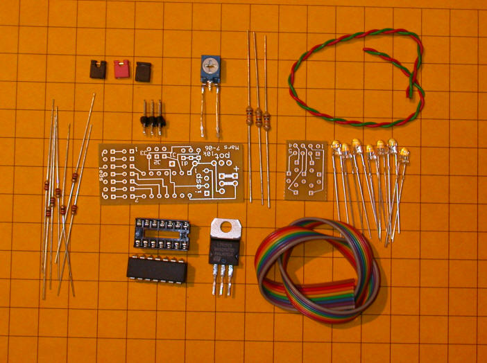
| 1. The parts for the kit are shown below. In
addition you will need a soldering iron with a fine tip, solder and
wire cutters
|
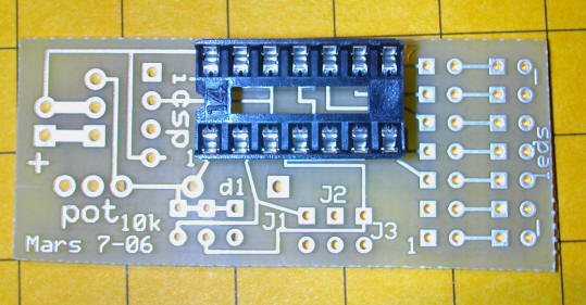
| 2. Insert the 14 pin socket in the circuit board.
Make sure that he small notch in the socket (that indicates the end
with pin 1) is aligned as shown. Solder the socket from the
rear making sure that the socket is held tightly to the board.
|
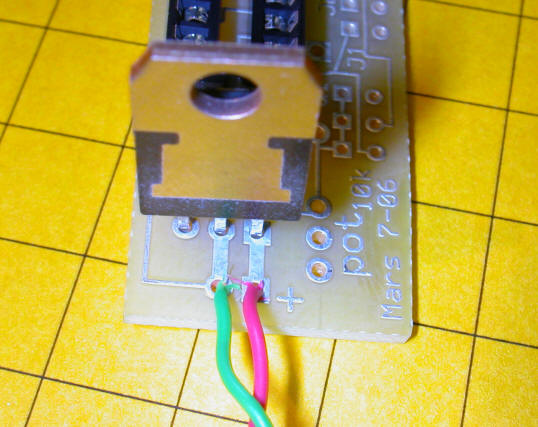
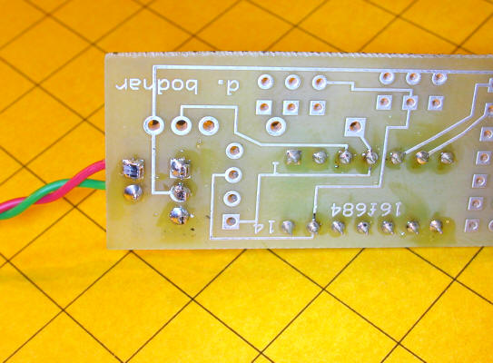
| 3. Insert the 7805 voltage regulator with the face of the device
aligned as shown here. Strip a bit of insulation from the red
(positive) and green (negative) power leads and insert them into the
+ and - holes in the board.
Solder from the back. Clip off the leads from the 7805 close to the board after soldering.
|
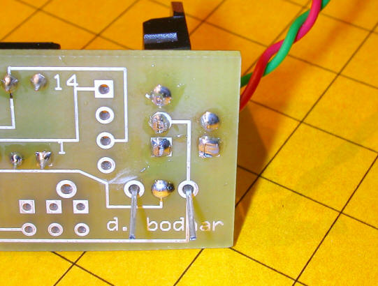
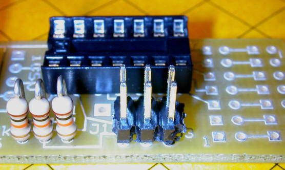
| 4. Insert the speed control potentiometer into the three
holes labeled "pot" - note that the center lead does not go
completely through the back of the board. To make sure it is
soldered properly solder just this lead first and pull up on the pot
to confirm the connection. Solder the outer leads and clip off
the excess.
|
|
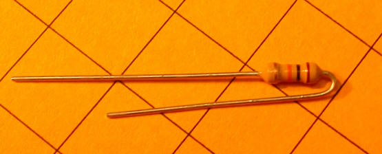
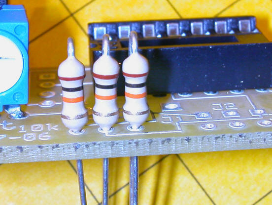
5. Bend the leads on the three 10,000 ohm
(brown/black/orange) resistors as shown and insert into the holes
right next to the pot. Solder and clip the leads.
It is easier to solder the resistor leads if you carefully bend them out of the way first.
|
| 6. Insert the 3 x 2 header into the six holes to the side
of the 10,000 ohm resistors. Note that the holes in the board
are a bit small for this header and that the shorter side of the
header pins have been ground down so that it will fit. This
board error will be corrected in the next revision of the board.
|
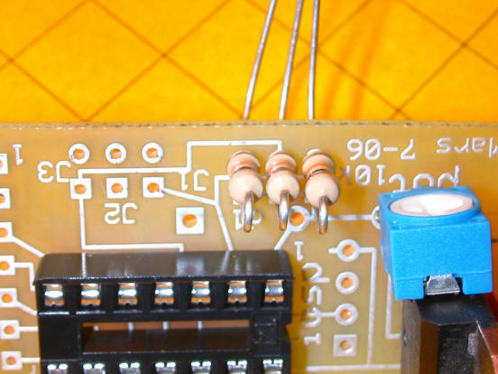
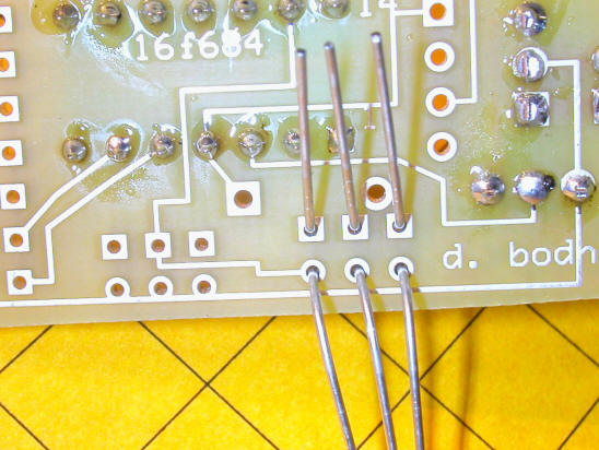
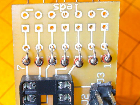
| 7. Insert either 4 or 7 of the smaller 200 ohm resistors
into the holes to the right of the IC socket. Bend the leads
as you did with the other resistors, bend the leads and solder.
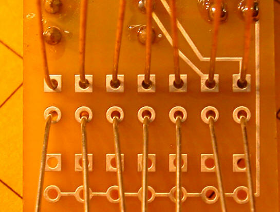
Clip the excess close to the board. Placement of 4 resistors if using the 4 LED light.
Placement of 7 resistors if using the 7 LED light.
Bottom view with leads bent before soldering.
|
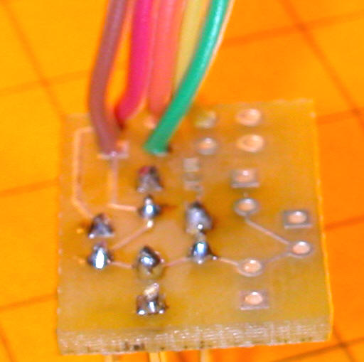
| 8. At this point stop and examine the board carefully for
solder bridges and poor solder joints. If you have a multimeter you can test the circuit for 5 volts - Supply 7 or more volts to the green / red power wires - Put the negative multimeter lead on the metal tab of the 7805 - Put the positive multimeter lead onto pin 1 of the IC socket - it is labeled "1" on the board - The meter should show 5 volts + or - a small amount
|
|
Kit Construction - Part 2 - LED Circuit Board - 7 LEDs |
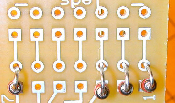
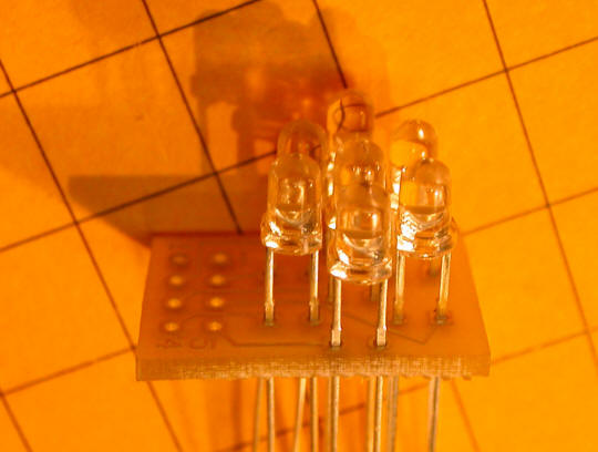
| 1. The 7 LEDs go into the 7 pairs of holes on the LED board. Note that each pair of holes has a round and a square solder pad. The longer (positive) LED lead goes into the square pad and the shorter (negative) lead goes into the round pad.. The 8 holes at the edge of the board are for the connecting wires that go to the main circuit board. They are numbered 1 x x 4 on the edge and - x x 5 on the 2nd row (x = no label) |
| 2. You can place the LEDs right against the board or some
distance away from the board. If you mount them away from the
board you will have an opportunity to focus the LEDs to the sides
should you want to. The only problem with mounting away from
the board is that the leads could touch and cause a short circuit. Just be careful to
keep them apart or insulate them with bits of heat shrink tubing or
insulation taken from other wire. If you are working with the 3 mm LEDs there is a small protrusion on the leads that will stop them all about 1/4" from the board. This is what is shown in the example photos. |
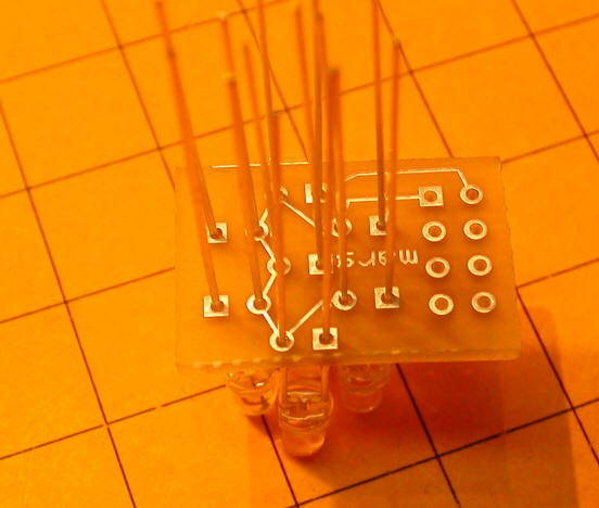
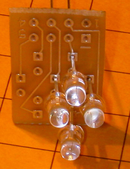
| 3. Carefully solder each LED lead from the side of the
board marked "Mars". It is best to solder just the positive
leads (those in the square pads) first to make sure the LEDs are
aligned properly and that each is an even distance from the board.
Once you are sure they are done properly clip the soldered leads and
solder the short leads. Clip them when done.
Here you can see the flattened area on the leads that keeps the LEDs spaced an equal distance from the board.
Double check that the longer lead goes trough the holes with the square solder pads.
Solder just the anodes (longer wires) first to check for even spacing.
Here all of the LEDs are soldered in.
|
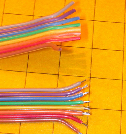
| 4. I generally use a short length of multi-conductor
ribbon cable to connect boards like these although any type of wire
could be used. To use the ribbon cable that is supplied with the kit separate the wires for about 1/2" at each end. Once separated carefully strip about 1/8" of insulation from each end of each wire.
Note that the wire can be inserted from the front or the back of the board. I find it best to have it going in from the back of the board (the side with "mars" written on it). That way the wire is less likely to interfere with the installation of the LEDs. |
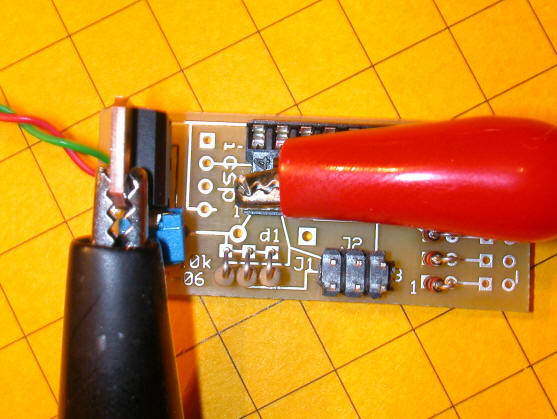
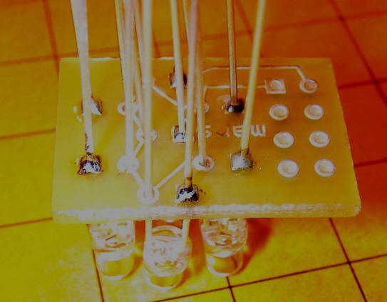
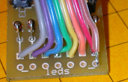
| 5. Choose a color to be the negative lead and another to
connect to pin 1. With the colored cable used here I chose
brown to be negative and grey to go to pin 1. Begin by
soldering the wire to just the LED board. Start with the
negative wire which goes to the hole marked with the "-" sign.
Note that this hole has a square solder pad around it. In this
photo five of the 8 conductors have been soldered.
|
| 6. Once the negative lead is soldered begin to solder the other leads. It is frequently best to insert a few at a time. Solder those and then do the rest. It may also help to "tin" the stripped ends of the wires so that bits of stranded wire doesn't sneak out and cause a short circuit. |
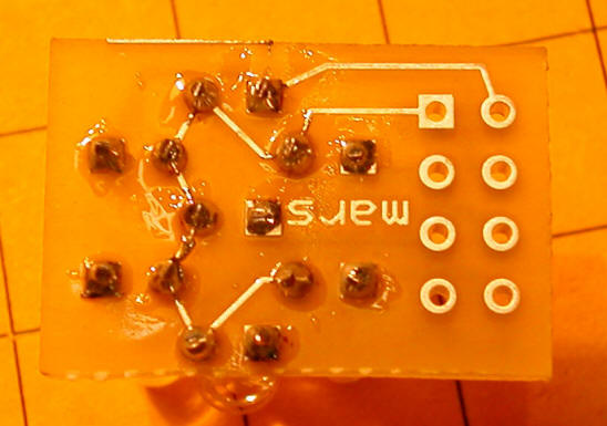
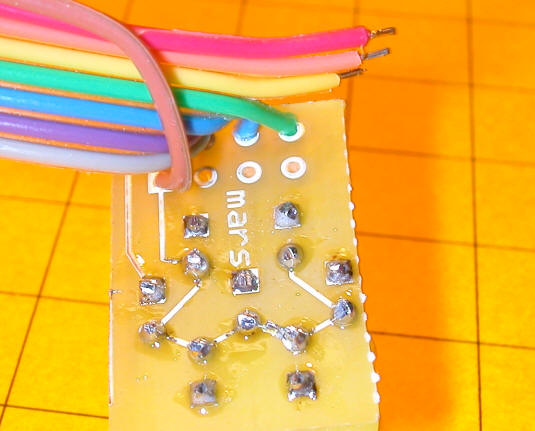
| 7. After completing the LED board connection continue by
soldering the cable to the main board. The negative wire can
go to any of the 7 pads on the very edge of the board. If you
look at the bottom of the board you can see that they are all
connected together. In this photo the brown (negative lead)
has not yet been soldered.
|
| 8. Check and double check your wiring and make sure that there are no sold solder joints or shorted connections. Some of the solder pads are very close together and it is quite easy to inadvertently cause a short. |
|
Kit Construction - Part 2 - LED Circuit Board - 4 LEDs |
| 1. The construction of the board for the 4 LED unit is identical to what was described above with a few minor exceptions |
|
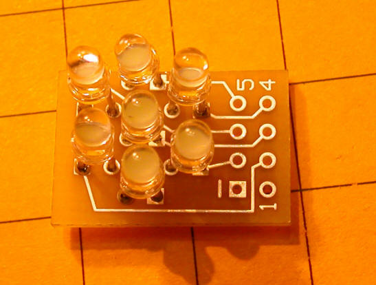
2. The 4 LEDs are inserted into the holes shown in this photo.
|
|
3. The cable is connected to these solder pads on the LED
board. The brown wire is negative, red goes to LED 1, Orange
to LED 2, Yellow to LED 3 and green to LED7.
|
|
4. The cable is connected to the solder pads on the main
circuit board with the same numbers. Brown to negative, Red to
1, Orange to 2, Yellow to 3 and Green to 7.
|
|
Final Assembly and Testing |
| 1. After making sure that everything is soldered correctly insert the microcontroller into its socket. You must insert the chip with the proper orientation. Note that pin "1" is marked on the top and bottom of the circuit board. There is a small dot on the microcontroller next to pin 1. Align the chip so that pin 1 lines up with pin 1 on the socket. |
| 2. You may need to bend the pins in a bit to get it to fit into the socket properly. When applying pressure to the chip to seat the pins keep looking under the chip to make sure that none of the pins are misaligned as it is easy to have one or more pins "buckle" underneath. |
| 3. Apply power to the power leads and one or more of the LEDs should start to flash immediately. If not quickly remove the power and double check connections. |
| 4. Set the jumpers according to your LEDs. If you are using 7 LEDs no jumper should be placed on the pins labeled "j1". If you are using 4 LEDs install this jumper. |
| 5. Turn the potentiometer full clockwise or full counter clockwise. The speed of flashing will either increase or decrease. Note that the unit only check the position of the pot once per cycle so it can take a few seconds for any change to be noted. |
| 6. Now you can experiment with the other patterns that are programmed into the microcontroller. Install a jumper on the pins labeled "j2" and / or the ones labeled "j3" |
| Schematic:
|