- Measure DC voltage from batteries
- Test 9 volt and 1.5 volt batteries under load
- Measure resistance and continuity
- Test track wiring connections
- Measure power supply voltage
- Measure current drawn by a locomotive or other load
- Troubleshoot a non-working engine
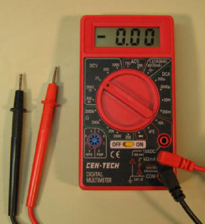
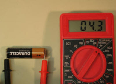
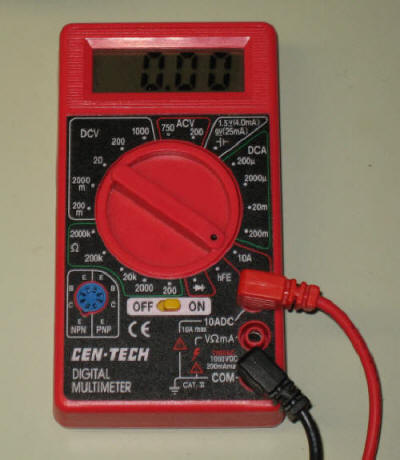
Insert the red probe into the center socket (labeled "VΩmA") on the meter and the black probe into the bottom one (COM). Turn the selector to the DCV 20 position and turn the meter on. The display should show 0.00 volts. There may be a leading "-" sign on the display as in this photo.
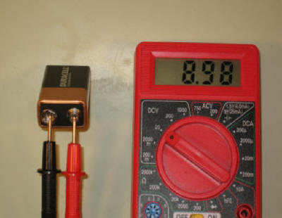
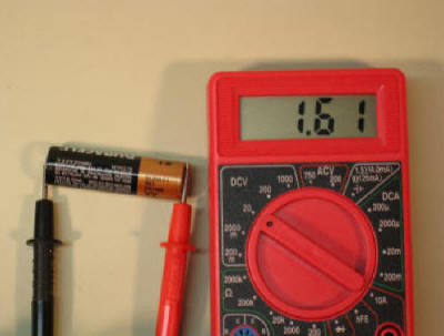
Touch the tip of the red probe to the positive terminal (the smaller terminal) of a 9 volt battery and the black probe to the negative terminal (the larger one). The display should show about 9 volts depending on the condition of the battery. Repeat the test with a 1.5 volt AA battery. If you inadvertently connect the probes to the incorrect terminals the display will show a negative voltage. This will not damage the meter.
Note: Measuring battery voltage in this way does not really perform a very good test as the batteries are not under load. This is what is called open circuit or open current testing.
You can perform a better test with 1.5 volt and 9 volt batteries. Do
not use this method with other types of batteries! Move the
meter's selector to the battery test position in the upper right between ACV and
DCA.
Again touch the red probe to the positive terminal and the black to the
negative. As the meter's label says a 1.5 volt battery should show 4 mA
and a 9 volt battery should show 25 mA.
This is a better test because it is done with the battery
going through a small resistor inside of the meter. This puts the battery under load so that a more accurate reading of its capacity
can be taken. Do not leave a battery connected too long as it will
discharge while being tested.
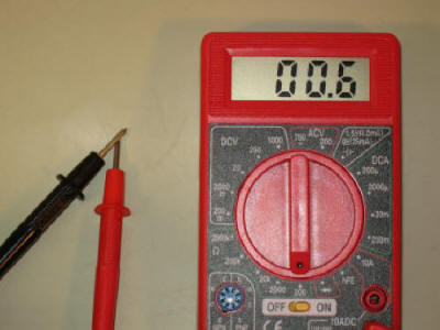
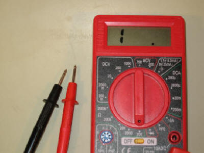
Set the selector straight down to the 200 Ω setting. Touch the two probes together and the meter should display "00.0" (zero) or a very small resistance of 1 or fewer ohms. Separate the probes and the display shows "1 .". When the meter reads "00.0" (zero) that means that there is no resistance between the probes indicating a good connection.
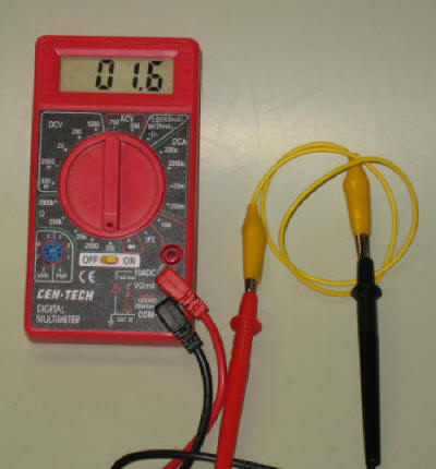
It is frequently easier to do tests using wires with alligator clips on their
ends rather than just touching the pointed probe ends to the test item.
Before using alligator clip jumpers use the meter to make sure that they are
working properly. Inexpensive jumpers are notorious for being faulty as
the connection between the wire and the clip is rarely soldered. Just
leave the meter set as we have it and connect one end of the jumper to each
probe. The reading should be just a little more than we see when touching the probes
directly. Repeat with the other probe or join the two together to test
both at the same time.
| Remember: Most inexpensive jumpers are poorly made. The wires are not soldered to the clip and the press fit is frequently less than a good connection. Always test jumpers before using them and solder any that give high resistance readings or are completely open. |
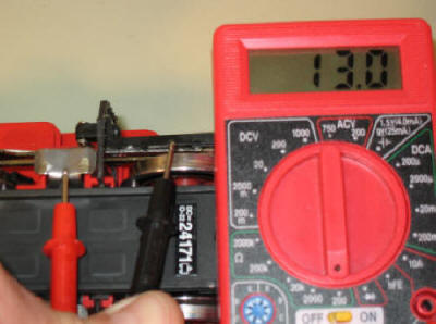
Let's test the connection between the wheels on a locomotive to see how well its contacts are working. Touch one probe to a wheel that has electrical pickups on it and the other to another wheel with pickups on the same side. You should see a reading of "00.0" or something very close to that, perhaps a few ohms. Try testing between the engine's sliders (if it has them) and a wheel. Again it should show low resistance. In this photo we see a resistance of 13.0 ohms between the sliders and the drive wheel. This is due to the carbon brushes on the wheel having a fairly high resistance . As long as the meter shows that there is a connection the motor should be getting power.
Note that it is not unusual to get an open reading, "1 .", when measuring wheel pickups. Sometimes the wheels stop at a point where there is not a good connection. Try moving the wheel back and forth to see if the connection improves.
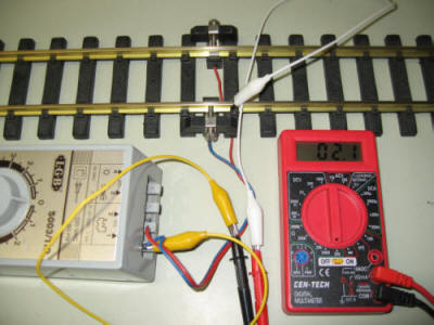
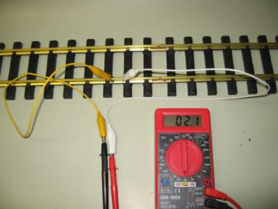
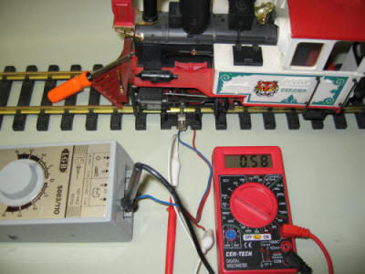
Let's test the wires that connect from your power supply to the track. WITH THE POWER SUPPLY OFF, connect one of the meter's probes to one end of the connecting wire. It is OK to test without disconnecting from the power supply's terminals, just make sure the power is off. Touch the other probe to the track. You should see either zero or a very small resistance. Try wiggling the connections. The reading should not change. Test the other wire to the track.
In this photo we are testing the blue wire from the power supply to the near
rail. Note that the power is set to "0"!
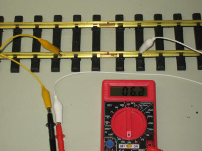
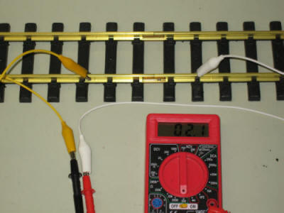
If you suspect that the connection between two pieces of track is poor you
can use the same procedure to check the resistance across that connection.
Track Test 1 - There is very little resistance when the two clips are on a
solid rail.
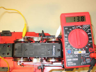
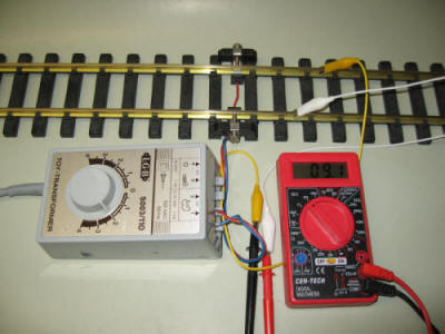
Set the selector to the DCV 200 setting. Note that we don't use the DCV 20 setting since most large scale power supplies can put out over 20 volts. Using the 20 volt setting will not hurt the meter but it will stop reporting a voltage when it reaches 20 volts.
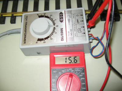
Use the alligator clips to connect one probe to one of the power supply terminals and the other probe to the other terminal. Set the speed control to zero or "Stop" and turn on the power supply.
Note that power supplies that use PWM or PWC will not give an accurate voltage reading as they put out a constant, high voltage but vary the on/off time to control speed.
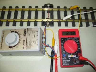
If the power supply has an auxiliary or accessory connection test that as well. If it is marked AC change the selector to ACV 200. The power supply terminals should show a reading close to the voltage printed on the power supply.
When a power supply is connected to a locomotive or other load you can use the meter to measure how much current the load is drawing. Up to now we have put the probes in parallel with the voltage we have been measuring.
In this diagram the probes go across the battery (power supply) or motor. This is the procedure that is used to measure voltage.
Measuring Current (probes in series with the current measured)
When measuring current one must put the probes in series with the power supply and the load .
In this diagram the red probe is moved from the center to the top. The circuit that operates the motor is broken and the two probes are inserted in series with them to complete the circuit. This allows the power to flow through the meter so that current can be measured.
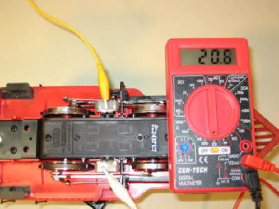
Put an engine on rollers or lay it on its side so that it can run without moving. Use the alligator clips to connect the power supply to the engine and get it running at low speed.
Unplug the red probe from the meter's center connection and reconnect it to the upper connection labeled 10ADC. Put the selector into the 10A position.
Disconnect one of the leads between the power supply and the engine. Use the meter's two probes to reconnect the power supply and locomotive.
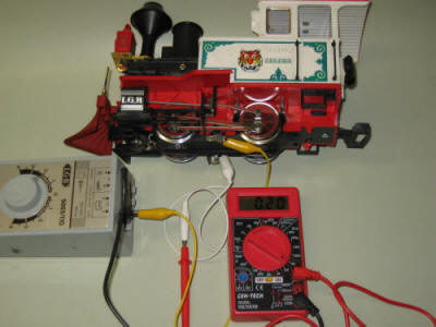
The motor should start back up again and a current reading, in amps, should show on the meter's display. Most small engines should draw little more than 1 amp.
Increase the throttle on the power supply. The amperage reading may change a bit.
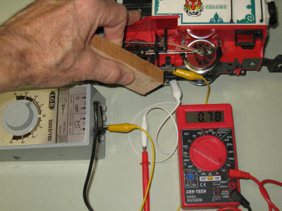
Push against one of the locomotive's drive wheels with a piece of wood to slow it down. The current reading should go up sharply showing that it needs more power to maintain its speed.
Although it is convenient to test engines on rollers or other static test stands it is not necessary as the same tests can be made on a train running on a layout. Just disconnect one of the leads to the track and connect the power supply in series as we did in the static test.
Make sure that you avoid connecting the meter to loads that have the potential to draw more than 10 amps. There is a fuse in the meter that will "blow" if 10 amps is exceeded.
| When you are done testing current make sure you return the meter's red probe to the middle terminal. If you inadvertently test batteries or power supplies by putting the probes across the power while in the 10 amp setting you will probably blow the fuse in the meter. |
You can test the "health" of your model railroad equipment by making periodic tests and noting any changes. When you get a new piece of electrical equipment make a few tests and record the results as benchmarks.
For a power supply record its maximum voltage. For locomotives measure the current drawn at different speeds and when pulling a number of cars.
If you think your equipment is failing test it again and compare the readings with the benchmarks that you made when it was working properly. This can give you a valuable clue in finding the problem.
|
||||||||||||||||||||||||||||||||
If you have an engine that will not run you can make a few tests based on what you have learned so far.
(These tests are based on the assumption that the engine is running very poorly or not at all)
- connecting the probes to wheels with pickups on either side of the locomotive. If you consistently get a reading of 0 the motor may have failed or the power pickups may need to be replaced.
- Test the power pickups by testing for continuity between two wheels or one wheel and one slider on the same side of the locomotive. If you get good continuity on both sides chances are good that the pickups are OK.
- Put the engine on the track or on rollers and test for amount of current being drawn. If the engine does not run or runs poorly and the current is excessive chances are good that the motor or a circuit board in the engine has short circuited.
- Disassemble the engine and test the continuity between the wheels and the motor contacts themselves. If there is good continuity between each side of the motor and the wheels the motor is probably bad.
- Remove the motor completely and connect it directly to the power supply to confirm that it has failed.