d. bodnar 7-11-2019
| An interesting sensor has come on the
market recently. While its operation is similar to that of a
PIR (Passive InfaRed) sensor it uses radio waves and can do some
sensing through walls and other objects. It also has a 360
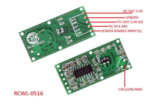
degree field of view. The purpose of this article is to show how this sensor can be used to control various devices including a relay and a novelty set of fairy lights. The sensor is shown here. It has five contacts on one end that are labeled "3V3, GND, OUT, VIN, CDS" The only connections we need for this project are the center 3, GND, OUT and VIN. The VIN pin can use from 4 to 28 volts, but the OUT pin only supplies 3.3 volts when the sensor is triggered. |
|
|
https://www.amazon.com/gp/product/B07MTWZDQZ/ref=ppx_yo_dt_b_asin_title_o08_s00?ie=UTF8&psc=1
or
|
|
| For more information on these devices I
strongly recommend viewing Andreas Spiess' video on YouTube.
He does a fine job providing details including adding a light sensor and changing the sensitivity and "on" time. |
|
|
|
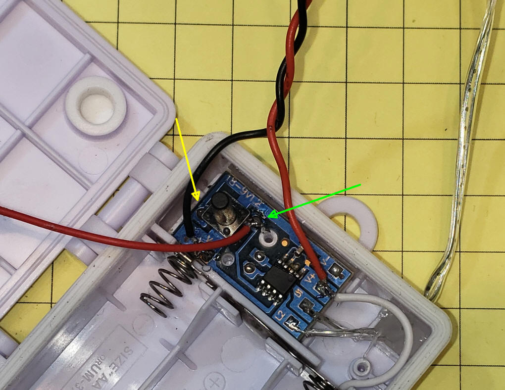
| Fairy Light Controller The sensor can be used to change the display mode of a set of fairy lights. This specific example is representative of other devices that have a button to control operation. Many such buttons are used to connect a logic pin on the controller to ground. That is what is done here. There are two connections between the button and the circuit board. The connection on the left (yellow arrow) goes to ground and the one to the right (green arrow) goes to pin 5 on the microcontroller. That pin is normally held high and is pulled low by pressing the button and connecting it to ground. Unfortunately the sensor board does not go to ground when movement is detected, it goes high. This is the opposite behavior that we want so we use a simple one transistor inverter to give the proper action.
In the schematic below Q1, a 2N2222 or similar NPN transistor, connects to the output of the sensor through a 1K resistor that goes to its base. The emitter of Q1 goes to ground and the collector goes to the switch connection to the right (green arrow). By wiring it this way every time the sensor detects movement the mode of the lights changes.
|
|
|
|
|
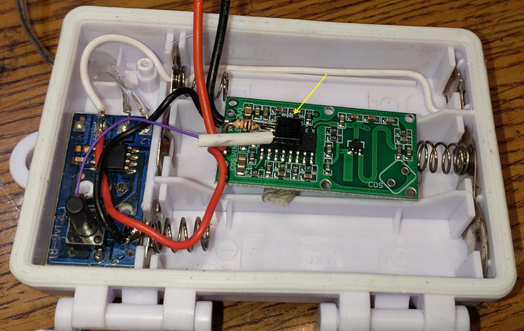
| Here the circuit has been installed inside
of the original battery box. The transistor (yellow arrow) is
placed on the sensor board and wired to ground, sensor output and
collector to the button pin on the circuit to the left. The
heavier red/black wires at the top go to a source of +5 volts.
Red to positive and black to
ground.
|
|
For those of you who might want to try
this with the same fairy lights you may find them if you search forLED Dual Color Micro Lights 4 Pack 1900220 --- some results may not be color lights, try to avoid these.
|
|
Triggering a Relay
|
|
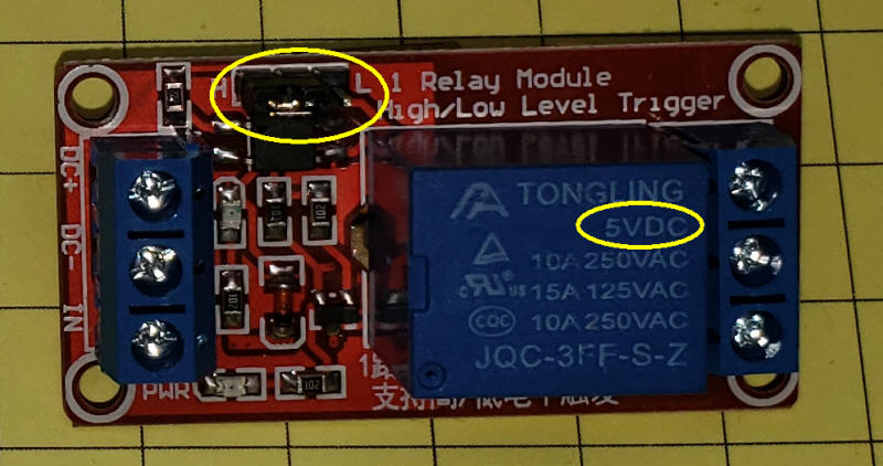
| Wiring for the relay couldn't be much
simpler. 5 volts is applied to the microwave sensor and to the
DC+ and DC- (ground) terminals on the relay board. When that
board is set to "H", for High, the output pin (out) on the sensor
goes right to the IN pin on the relay board. Once that is done you can connect your other device to the COM (common) and either the NO (normally open) or NC (normally closed) terminals for the relay. Simple!
|
|
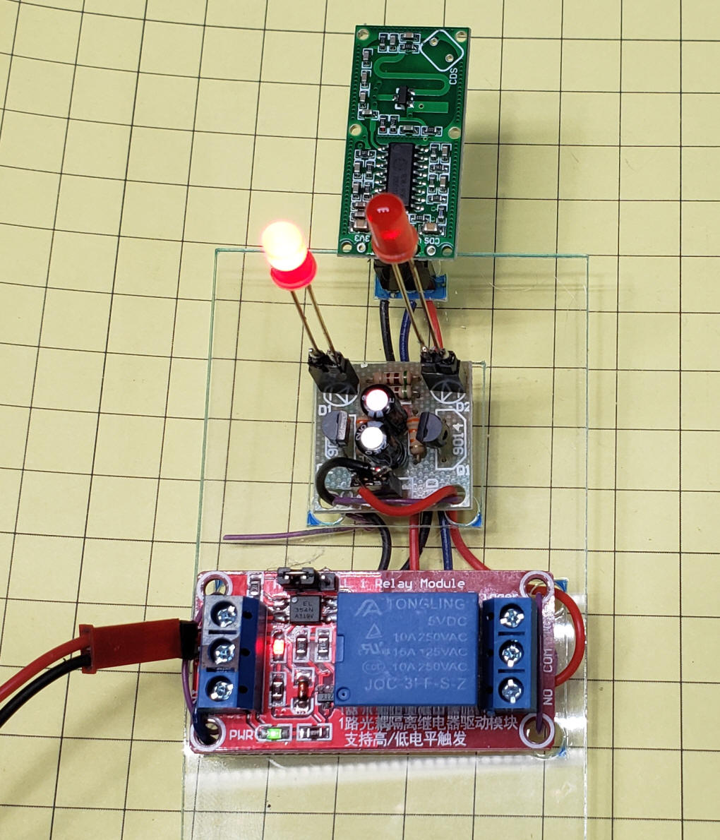
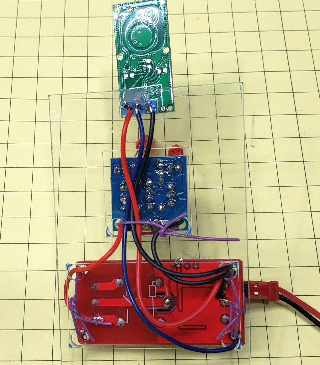
| Here is a basic demo that I built up from
the sensor, relay board and
a dual LED flasher kit
This schematic shows how it was wired.
|