|
1
|
|
|
2
|
|
|
3
|
- Retired from public education
- An active model railroader for 6 years
- Electronics, ham radio, woodworking, computers & programming have
been hobbies for decades
- Model railroading is a nice way to utilize those other interests
|
|
4
|
- Primarily interested in:
- using my electronics skills to enhance what can be done with a model
railroad
- Building custom circuits for model railroads
- Making presentations & writing articles about how to “roll
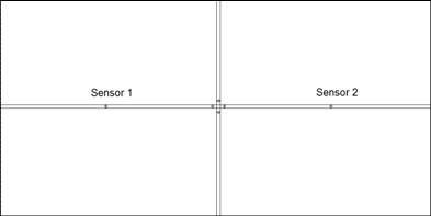
your own” circuits to satisfy my teaching instinct!
|
|
5
|
- Provide an overview of “hobbyist” microcontrollers
- Show how microcontrollers are programmed and connected to interact with
railroad equipment
- Demonstrate various devices & projects that utilize microcontroller
operation
- (Hopefully) Excite you with the possibilities and enable you to begin
experimenting!
|
|
6
|
- We all have an interest in how things work and many of us have enough
knowledge of basic electronics to know that something can be done…
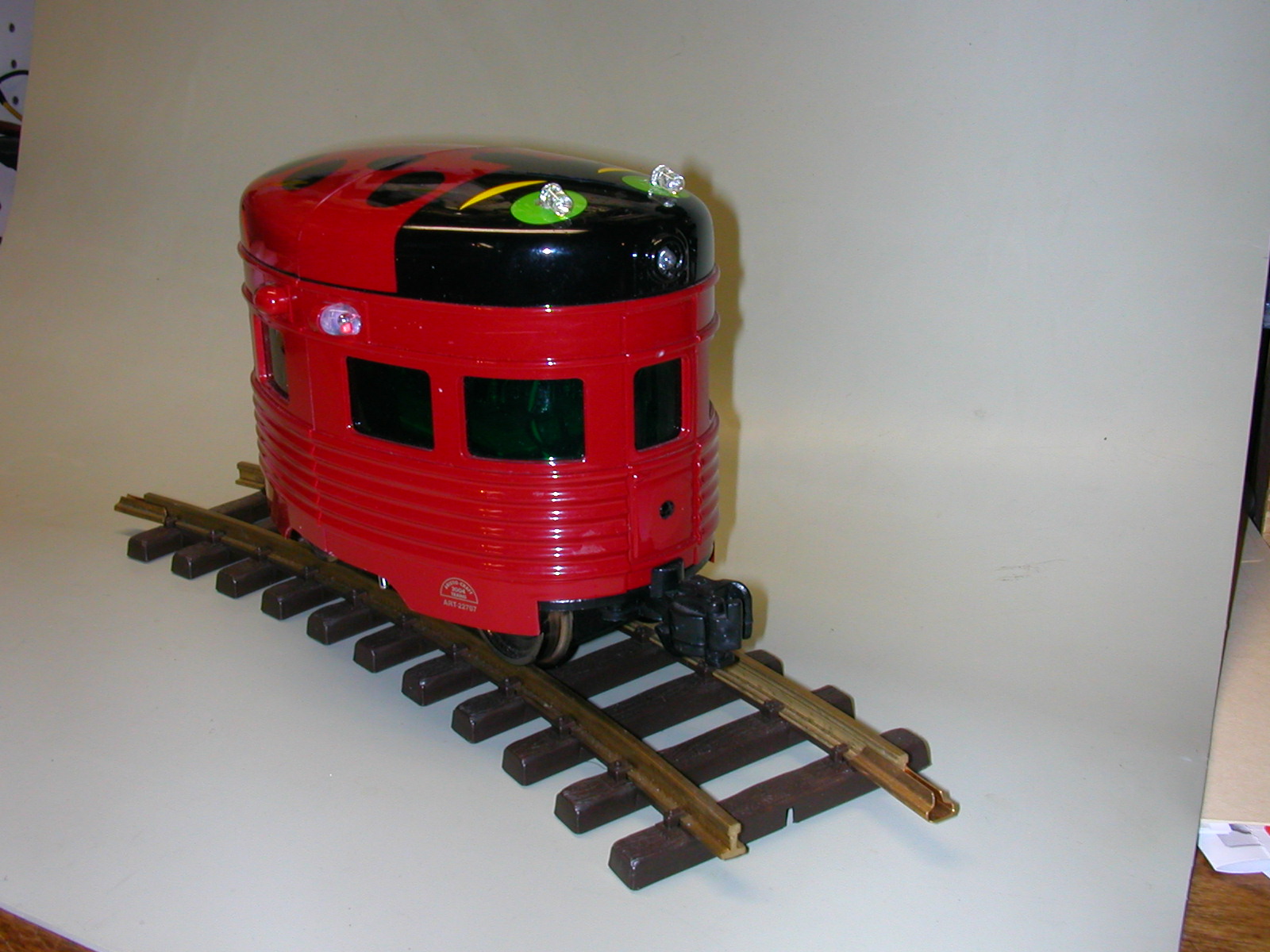
- we just need a bit of
help putting all of the parts together to make it happen!
|
|
7
|
- We Already Know About & Have Experience With:
- Batteries & power supplies
- Track wiring & motors
- AC, DC, voltage, amperage & resistance
- LEDs & incandescent bulbs
- Series & parallel circuits
- Switches, relays & transistors
- Programming
|
|
8
|
- Inexpensive
microcontrollers allow us to optimize the basic electronics and
programming knowledge that we have so that we can do some amazing
- (and personally
satisfying)
- things!
|
|
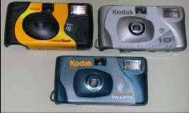
9
|
- They have been around for almost 20 years
- Usually dedicated to a single purpose
- Small
- Inexpensive (lately!)
- Programmed in BASIC
- No special programmer needed
- Found in many railroading devices (DCC, sound, radio control)
|
|
10
|
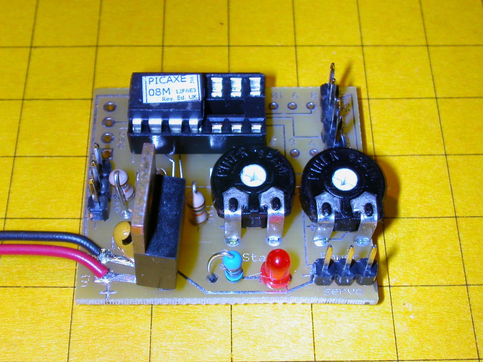
- Designed in the UK for use in schools
- SUPERB support
- Free manuals, tutorials and software
- Active & helpful forums on their web page & elsewhere on the web
- PICAXE manuals, especially “section 3- Interfacing Circuits”
are super in helping to put it all together on your railroad
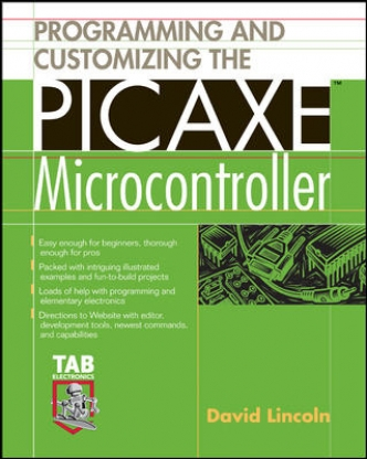
- Book: “Programming
& Customizing the PICAXE Microcontroller”
|
|
11
|
- Best choice in terms of:
- Capability
- Ease of use
- Cost
- Support
- dave@davebodnar.com
- Many PICAXE articles at Large Scale Online &
- www.trainelectronics.com
|
|
12
|
- Underlying chip (PIC) is from MicroChip
- … about 2 miles up the road right here in Chandler!
- How is that for a local connection to a British product?
|
|
13
|
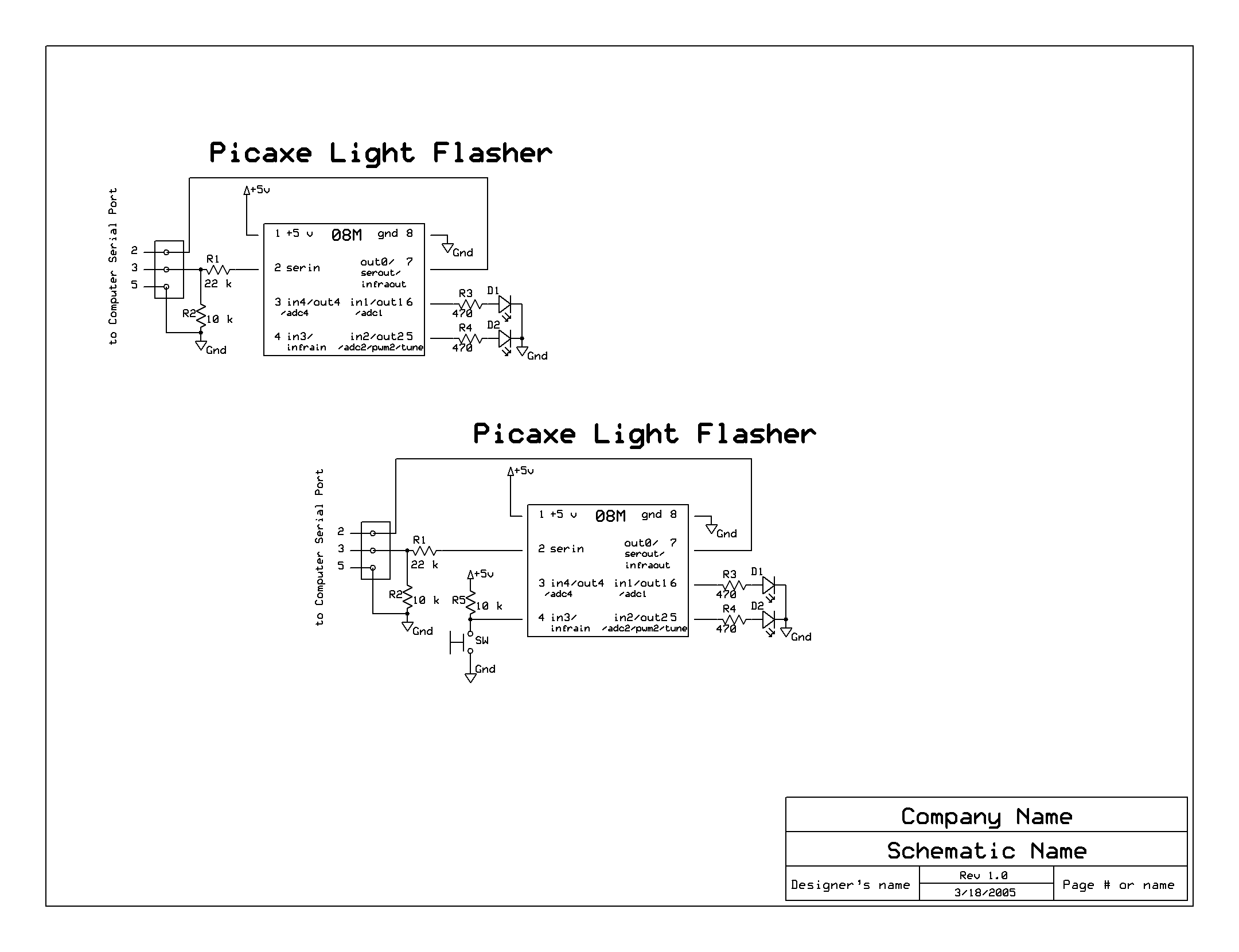
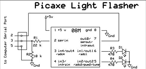
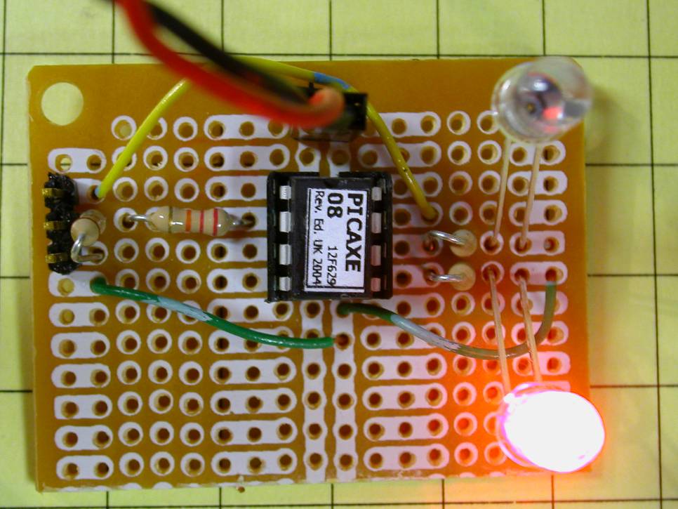
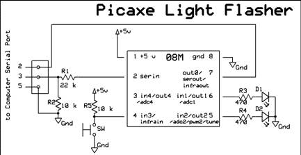
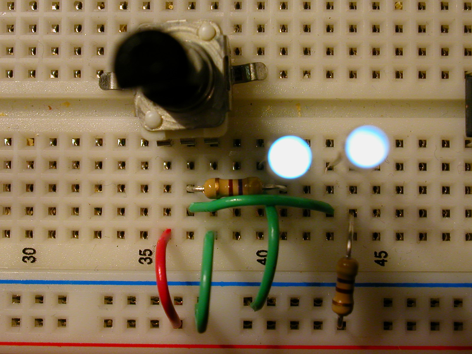
- Design objectives:
- Alternately flash two red LEDs
- Operate from battery power
- Alter timing and other characteristics from software
|
|
14
|
- Then we will modify the circuit to:
- Start from a button push
- Do other “flashing” things by making minor changes in
hardware & software
|
|
15
|
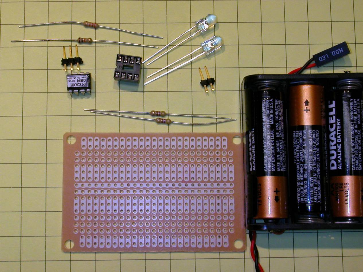
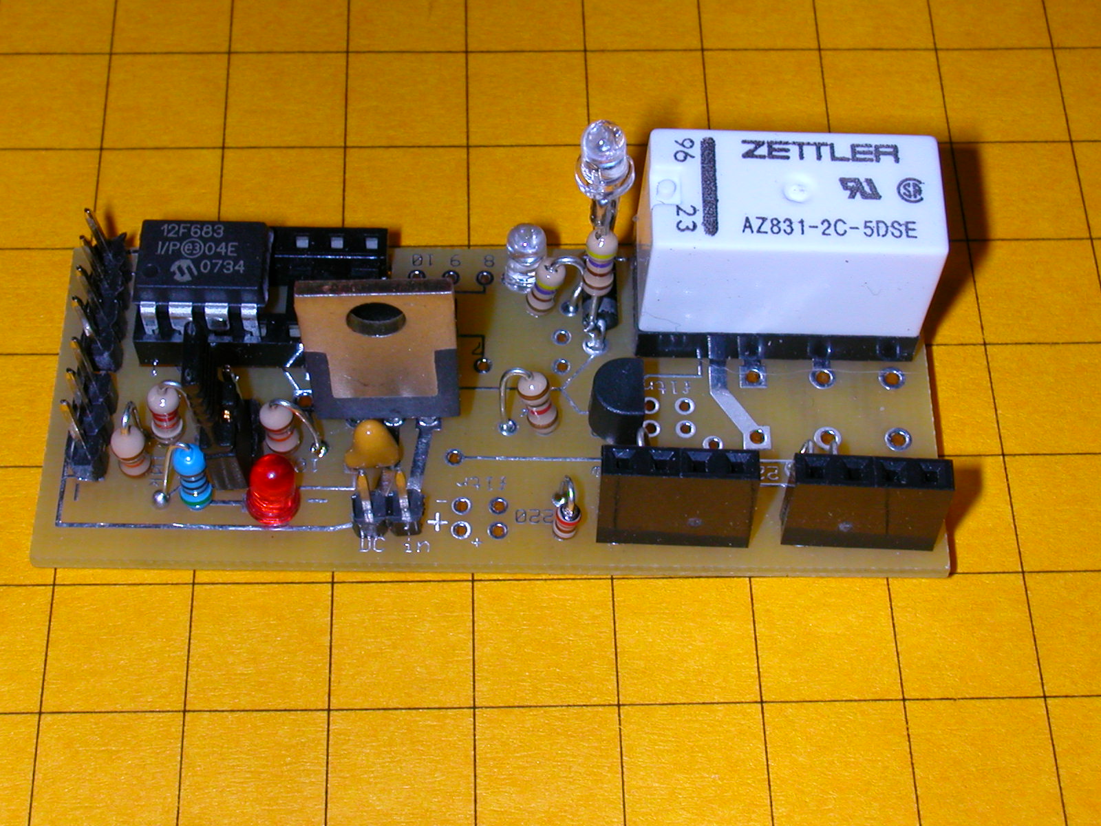
- Parts:
- Cost:
- Less than
- $10.00
|
|
16
|
- Software: free from www.picaxe.com
|
|
17
|
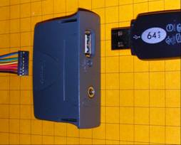
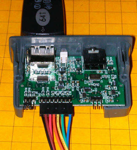
- Other items needed:
- Any Windows PC with serial port (or USB to serial adapter)
- Programming cable
- Needs only 3 wires - can use an old mouse cable
- http://www.allelectronics.com/cgi-bin/item/CON-243/search/3-PIN_CONNECTOR_W_HEADER,_.1%22#34;_.html
- http://www.allelectronics.com/cgi-bin/item/DB-9S/search/D-SUB_CONNECTOR,_9_PIN_FEMALE_.html
- Soldering iron & wire cutters, etc.
- A Solderless Development Package is available from www.phanderson.com
for < $20.00
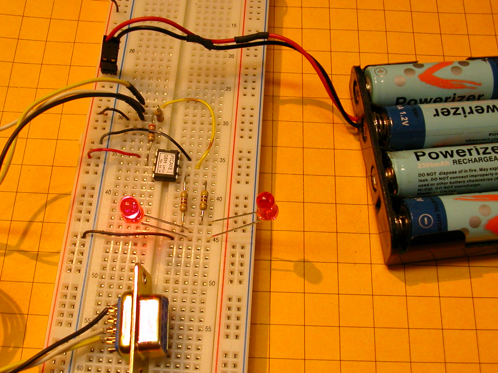
- 4 to 5.5 volt power supply (3 @ AA cells)
|
|
18
|
|
|
19
|
|
|
20
|
|
|
21
|
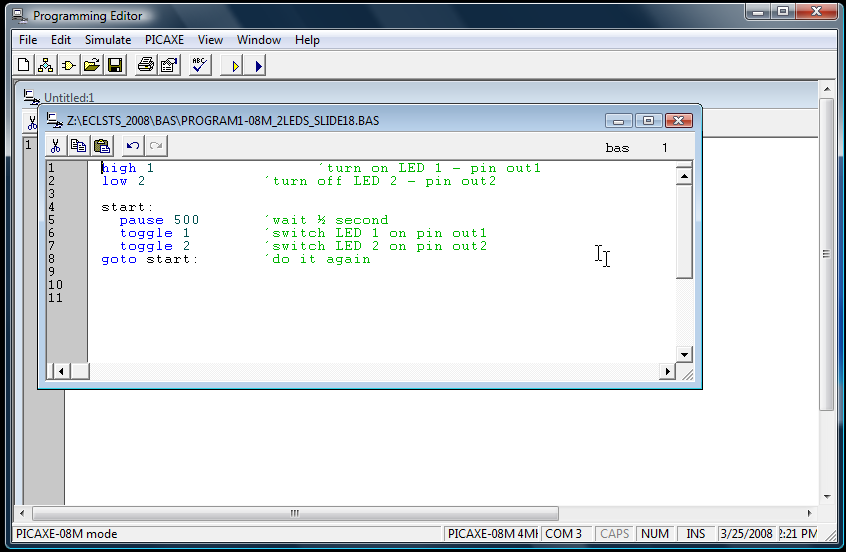
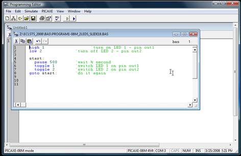
- Program 1:
- Notes:
- “start” is just a label telling the “goto”
where to go
- the program remains in the chip’s memory until it is manually
erased or overwritten.
|
|
22
|
- Program 2: modified to flash for 10 seconds and turn
- off for 10
- seconds
|
|
23
|
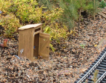
- Hardware modification for button or reed switch activation:
|
|
24
|
- Program 3: modified to flash 5 seconds on each button push
|
|
25
|
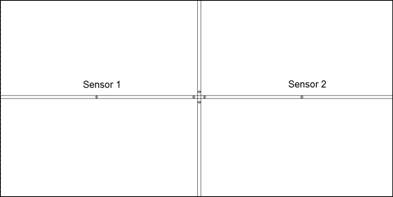
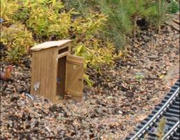
- Add a second sensor so that the light goes on when it passes one
sensor…
- …and goes off when it hits the other sensor.
|
|
26
|
|
|
27
|
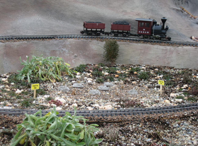
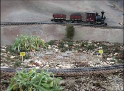
- The two sensor crossing light control can easily be modified to make a
“safe crossing” that can be used by two trains
|
|
28
|
- When the first sensor is reached the power is removed from the secondary
line
|
|
29
|
- Once the main line train has passed the second sensor the power is
restored
|
|
30
|
- We substitute a relay for the LEDs.
It controls the power to the secondary line
|
|
31
|
- Clever placement of diodes allows one relay to control the train
movement based on direction of travel
- The train never
stops after it has
already passed the
crossing, only
before the crossing
|
|
32
|
- More sophisticated optical sensors only release the stopped train after
sensing that the last car of the main line train has passed
- End Digression #1
|
|
33
|
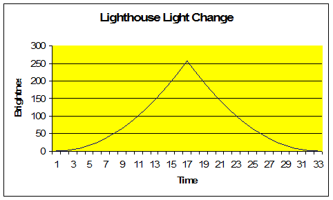
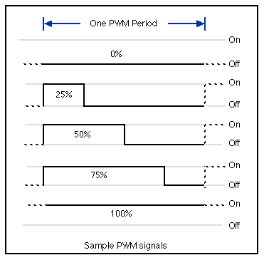
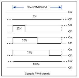
- Design objectives
- Gradually brighten a bulb or LED to near full brightness
- Momentarily flash to full brightness
- Gradually dim till off
- Delay for a set time
- Repeat
- Able to use LEDs or incandescent bulbs
|
|
34
|
|
|
35
|
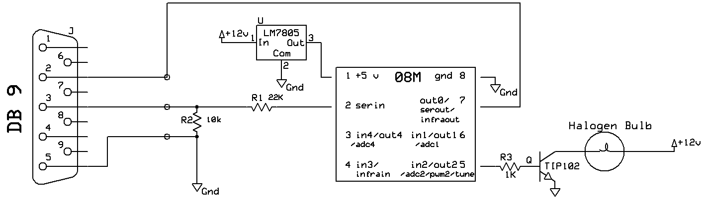
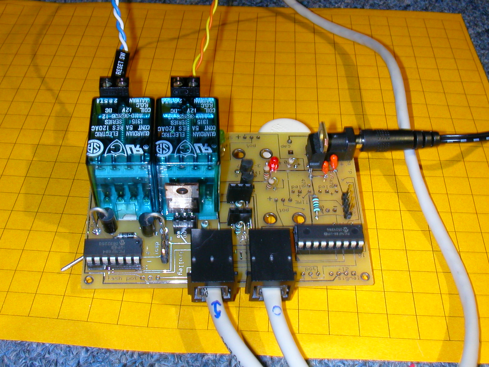
- Parts
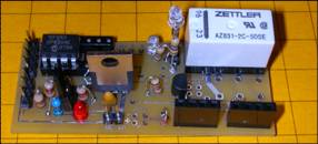
- Adds one resistor and one transistor to the original flasher circuit so
that the PICAXE can control a high current bulb
- The most significant changes are to the software
|
|
36
|
|
|
37
|
|
|
38
|
|
|
39
|
|
|
40
|
- The transistor makes it possible to drive a very bright bulb
- Substitute a motor for the bulb and you can control a train’s DC
motor!
- The size of motor is only limited by the size of the transistor
|
|
41
|
|
|
42
|
- Lights
- Motors
- Turnouts
- Relays
- Most electrically powered devices
|
|
43
|
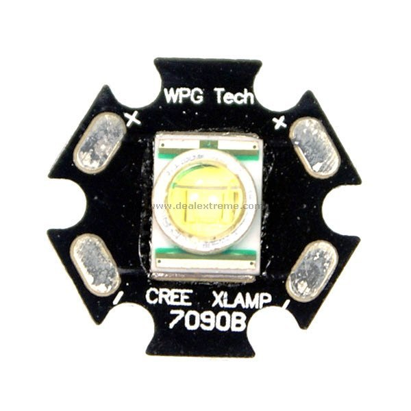
- LEDs have certainly come a long way in the last 10 years
- They are bright enough to be used as headlights on our model locomotives
|
|
44
|
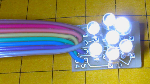
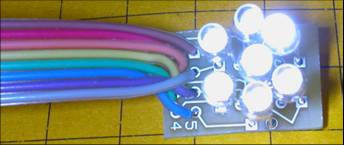
- Groups of LEDs can be configured to do some remarkable things
- …like creating a realistic Mars light
|
|
45
|
|
|
46
|
- Or even a headlight that is too bright to view directly
- That can turn into a single bulb Mars light
- End Digression #2
|
|
47
|
- Time
- Switches of all kinds
- Toggle switch
- Push button switch
- Reed switch & magnet
- Any type of sensor
- Motion, sound, temperature, light, etc
- Note: several articles on
sensors at LSOL
& www.trainelectronics.com
|
|
48
|
|
|
49
|
|
|
50
|
|
|
51
|
|
|
52
|
|
|
53
|
|
|
54
|
|
|
55
|
|
|
56
|
|
|
57
|
|
|
58
|
|
|
59
|
|
|
60
|
|
|
61
|
|
|
62
|
|
|
63
|
|
|
64
|
|
|
65
|
|
|
66
|
|
|
67
|
|
|
68
|
|
|
69
|
|
|
70
|
|
|
71
|
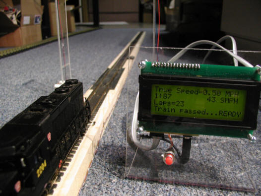
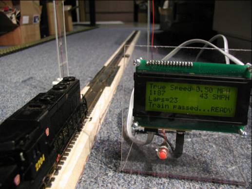
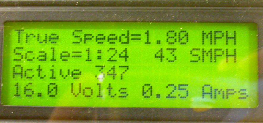
- Final design:
- 4 line x 20 character backlit LCD display
- Supports scales from 1:1 to 1:220
- Common scales identified by name
- Track-side sensors
- Counts laps
- Gives speed in real & scale MPH
- Option to “beep” out speed
- English or Metric units
|
|
72
|
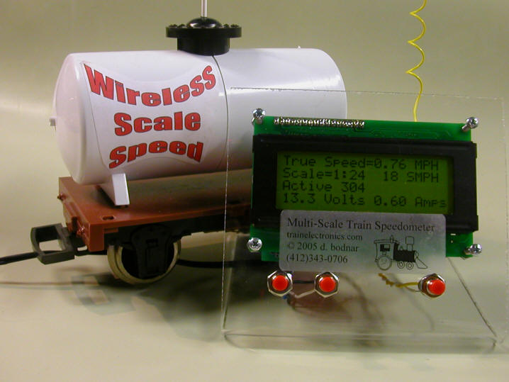
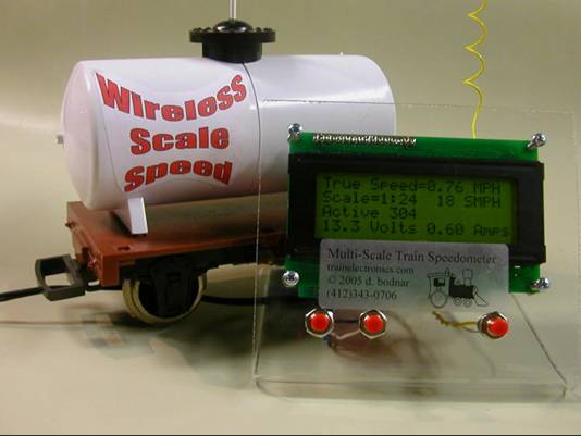
- Wireless option:
- Uses radio transmitter on a modified car
- Senses train speed and sends it to the display unit
- Also can report voltage and current on a battery operated engine
|
|
73
|
- Voltage and Current can also be included in the packet that is
transmitted
|
|
74
|
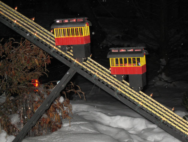
- Originally designed to operate the motor on my holiday incline
- Repurposed the Speedometer by adding a power transistor, relay and
additional control buttons
|
|
75
|
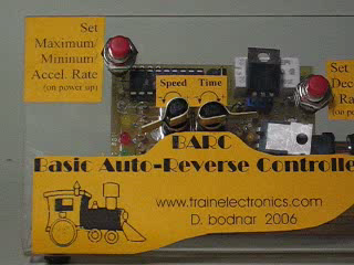
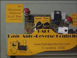
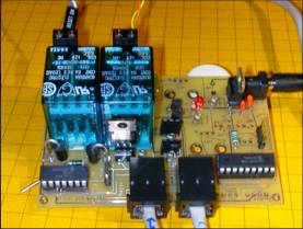
- BARC
- 2 Potentiometers to adjust time / speed
- 2 Buttons to set options
- Mosfet to handle high (10 amp+) current motors
- 3 LEDs to show time & laps completed
- 176, 172, 167, 163, 158, 154
|
|
76
|
- Dual tower lift bridge
- geared stepper motors
- TV remote control programming
|
|
77
|
- Crossover collision avoidance control
- Main line & trolley point-to-point cross
- Sensors operate trolley and stop or start it based on the position of
the train
|
|
78
|
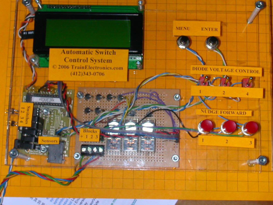
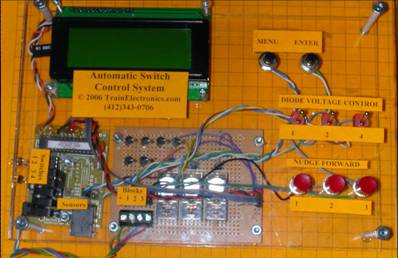
- Complete 3 train switching controller
|
|
79
|
|
|
80
|
|

 Notes
Notes