PCC Trolley Notes
revised 1-15-2011
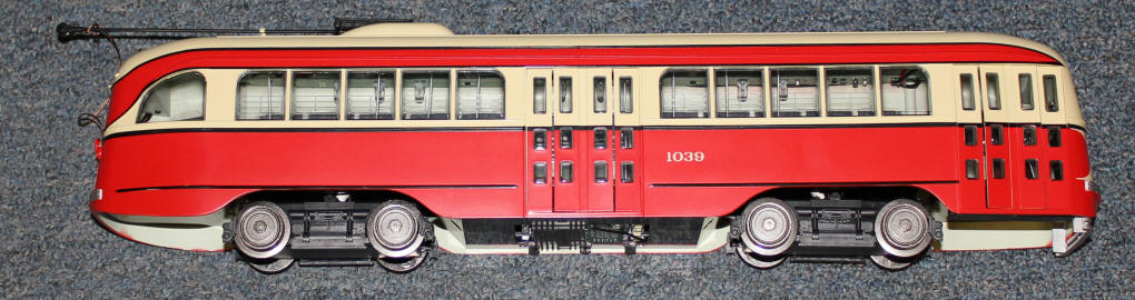
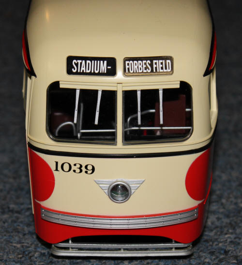
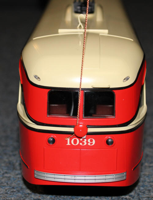
This is the Aristo Craft PCC Trolley - Pittsburgh.
Nice tribute to Forbes Field.
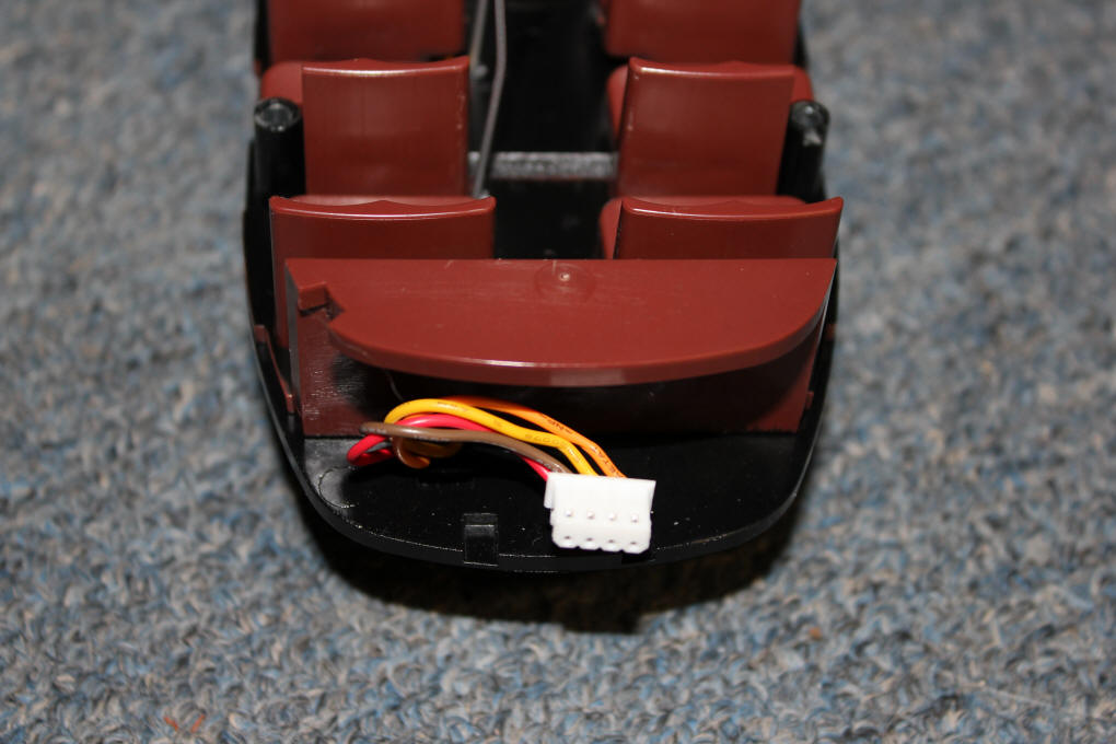
The top comes off after removing four screws. A four position plug allows for easy separation of the top and the bottom of the trolley. Here you can see the chassis plug.
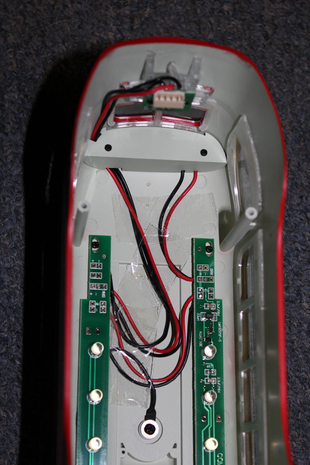
... and here the body plug can be seen at the top of the photo. You can also see the wiring to the power pole (black wire at bottom center) and a few of the 20 LEDs that illuminate the interior.
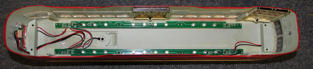
This view shows all 20 LEDs.
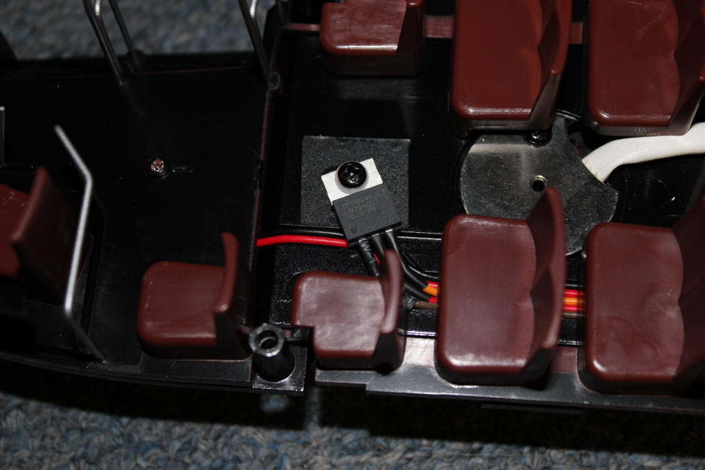
The device mounted to the interior of the car is a voltage regulator, an LM7940-5, five volt, low dropout unit. It is responsible for supplying power to all of the LEDs and needs some air to stay cool!
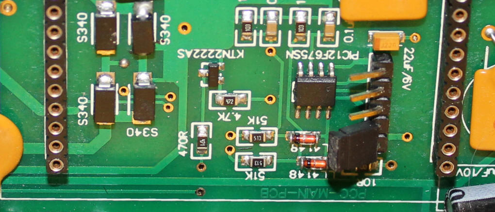
The circuit board that resides under a cover on the bottom of the trolley is shown here. A number of components are highlighted:
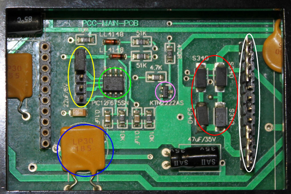
Although I have not removed the circuit board to do a complete examination of
the connections on the other side I can make an educated guess about how the
brake light function works.
The microcontroller monitors the voltage going to the motor through a voltage
divider (made up of some of the resistors shown in the photo). When a
significant drop in voltage is detected the brake light LEDs are turned on for a
few seconds.
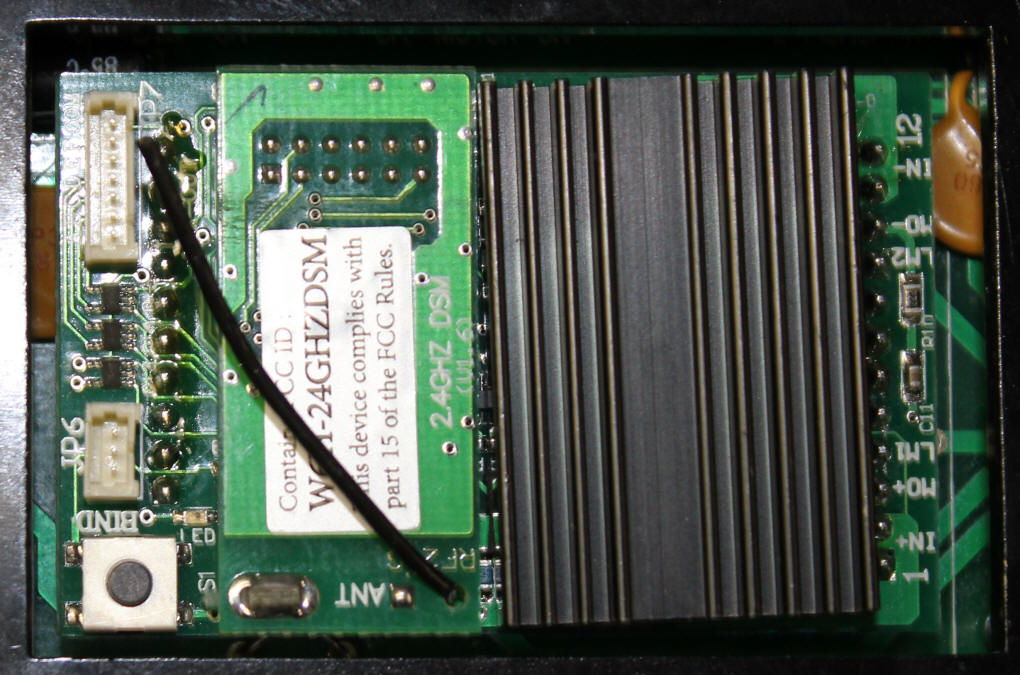
Here the Revolution receiver has been installed. Very little space remains.
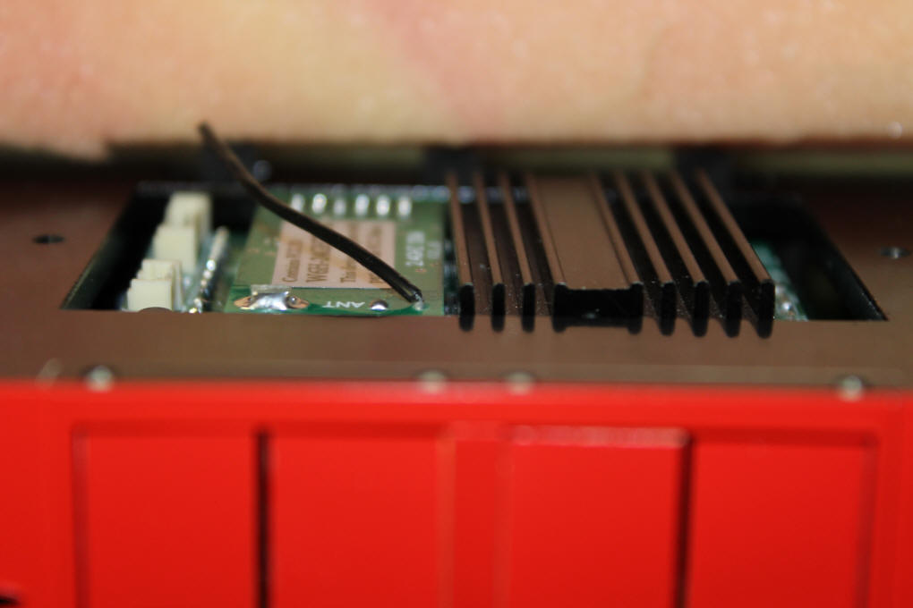
The side view shows that it projects very little above the frame and easily fits under the cover.
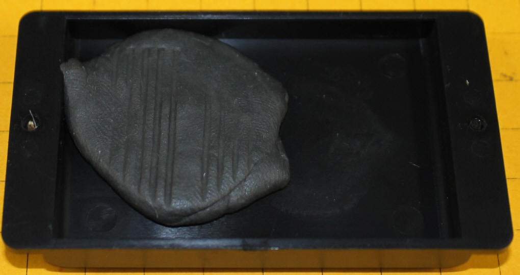
Clearance
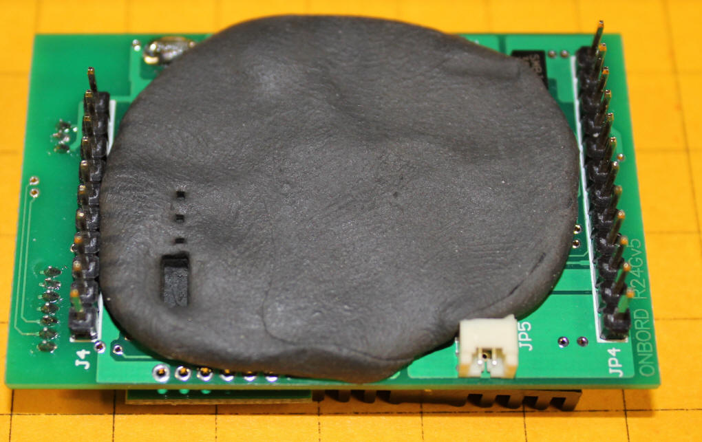
There has been some question about clearances below the Revolution circuit
board. I placed a blob of putty on the bottom of the receiver. It is
about 1/8" thick. As you can see the jumper and three pins from the header
penetrated the putty. There is about 1/32" of material left under the
jumper. If you are concerned about contact and possible short circuits it
might be wise to place a piece of electrical tape over the bottom of the
appropriate section of the receiver.
You could also bend over the five pin header as shown here. If done carefully you can still use the jumper and the programming header is still accessible. If you are not concerned about making more permanent changes to the circuit board there is no reason to keep the three pins that are not jumpered as they are only for programming the microcontroller and are unlikely to ever be used.
Top Clearance
This photo shows the same blob of putty on the cover of the electronics
compartment. The ridges are from the heat sink on the Revolution.
The putty is at least 1/8" thick and the grooves show that there is ample
clearance above the heat sink.
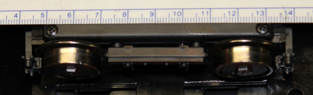
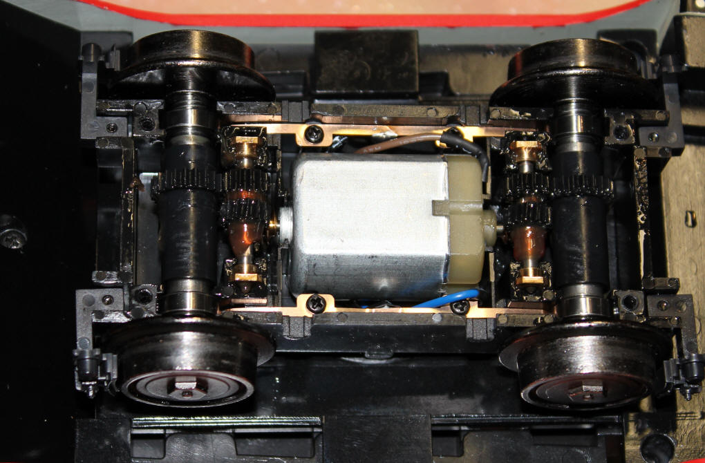
Trucks
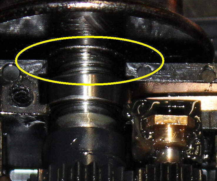
One of the trucks is shown here with its cover removed. Both axles are
driven and all wheels have electrical pickups. There is a worm gear at
each end of the motor that drives a gear on an intermediate axle. A second
gear on that axle drives the main axle.
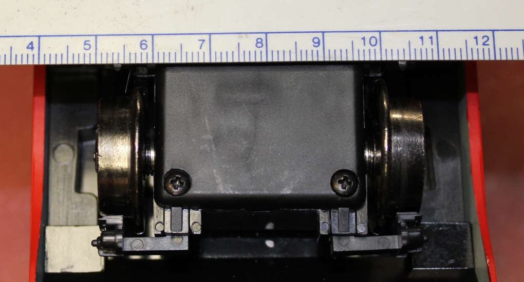
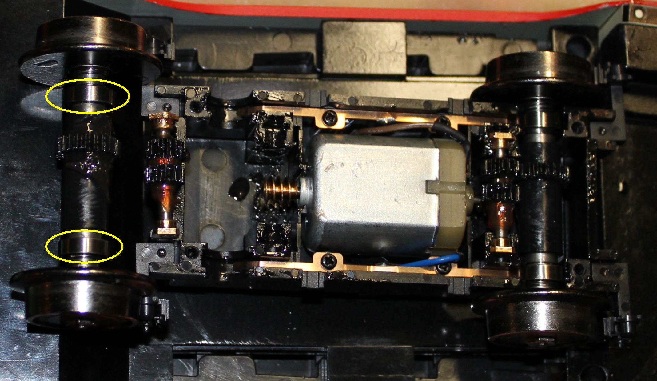
There are ball bearings at each end of the main axles (circled in yellow) - also note that the main axle and intermediate axle have been removed in this photo.
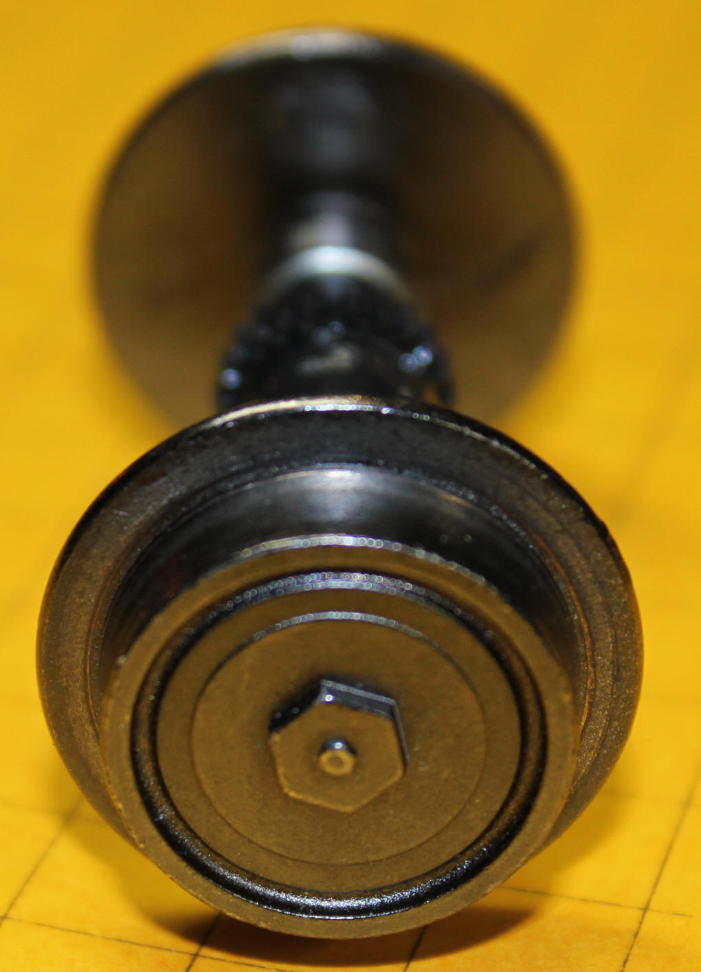
This detail shows a spring that keeps the axle centered.
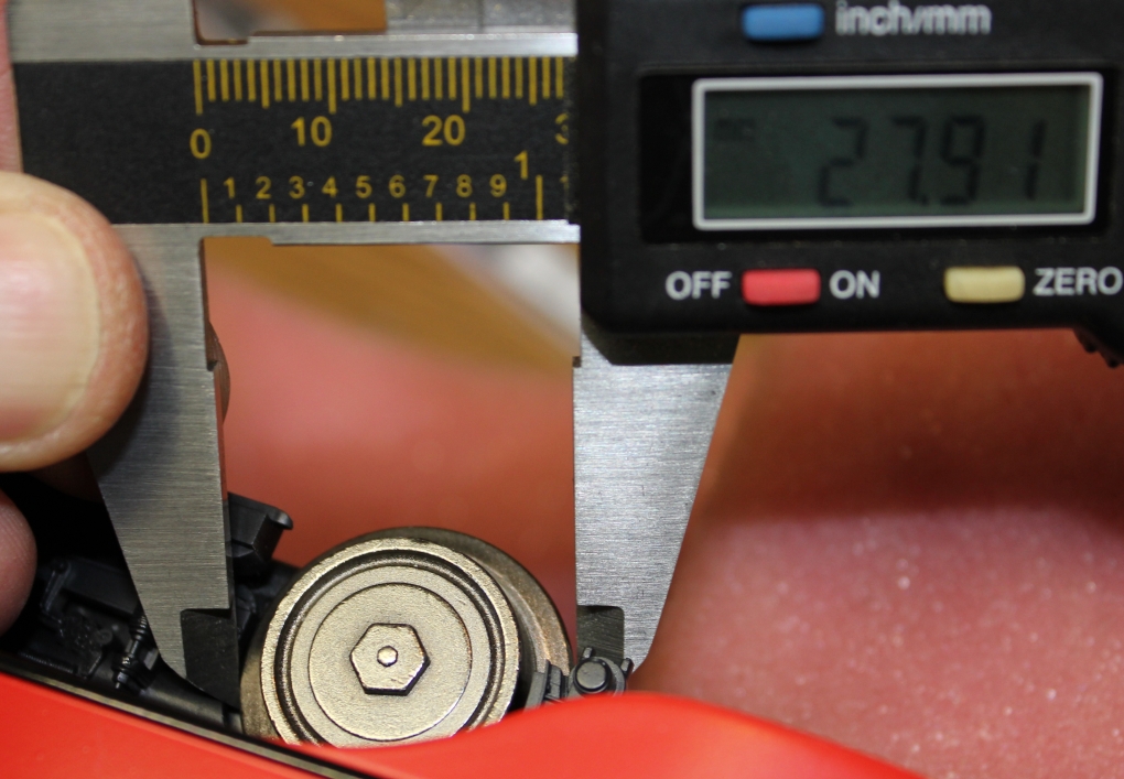
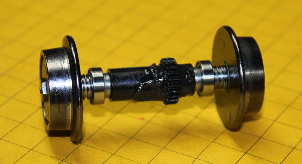
Here is a close-up of one of the axles. The bearings and springs are clearly visible.
This short video shows the trolley on rollers.
<right click the box below and select "play">
This VERY short video shows the axle rolling across a flat surface.
<right click the box below and select "play">
<right click the box below and select "play">
<right click the box below and select "play">
Observations while Running Under Track Power
All in all a very good runner!
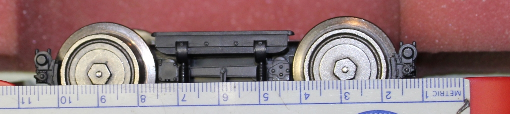
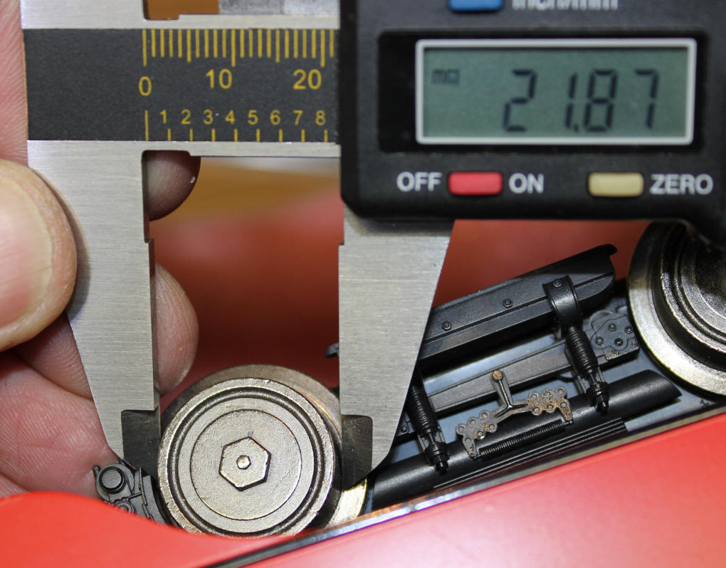
Dimensions
The Trolley is 485 mm long and 82 mm wide at its widest.
These photos will give you an idea of the truck dimensions. All measurements are in millimeters.