I am always on the lookout for ideas for animations that can
be used on a model railroad. Over the years I have used electric
motors, servos, solenoids, and dozens of arrangements of gears, cogs and
cams to make things move!
My latest project involves repurposing a home made magnetic pendulum to
animate a gymnast who swings back & forth on a horizontal bar.
The idea came to me after reading an article in the
September 2009 issue of an electronics hobbyist magazine called
Nuts &
Volts. The article described a pendulum that would swing back and
forth for weeks and weeks on the power provided by a battery made up of only
two AA cells. The electronic circuit was simple and I had most of the
parts for it
on hand. The main component that I lacked was the wire to hand wind a
coil. I found the magnet wire that I needed on eBay and ordered it
so that I could make my own version of the pendulum.
Once I built up a pendulum that was similar to the one was featured in the
article I began work on the
gymnast. The timing was perfect as the Pittsburgh Garden Railway
Society was preparing a layout that would be displayed during a three day
Oktoberfest that was being held in a nearby town. The theme was a
circus and I thought the animated gymnast would fit right in.
In this article I will show you how to build the basic
pendulum and then turn it into the swinging gymnast that is sure to add life
to your layout!
Building Overview
Building the pendulum is fun and relatively easy. I'll describe here how I
built mine. You can also see a
similar design on the Internet at:
that includes a wonderful explanation of how it works. This is highly
recommended reading, especially for those of you who will be tasked with
explaining how it works to friends and visitors.
Four subsystems comprise the unit:
A coil that goes directly under the pendulum
An electronic circuit that senses the passing of the
magnet on the pendulum and gives it a push each time it goes by
A stand and horizontal bar to hold the pendulum
The pendulum itself
The Coil
The coil is made up of several hundred feet of
28 gauge
magnet wire that is wound on a plastic form. Magnet wire is coated
with a varnish or paint based insulation rather than the plastic insulation
that we normally see on wire. This allows more wire to be wound on a
coil of a given size.
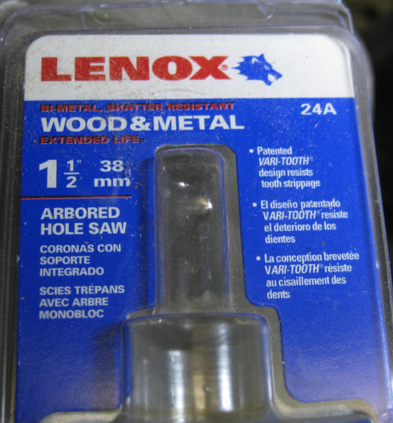
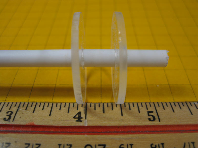
The form is made up of two 1 1/4" diameter disks of
3/32"
Plexiglas and a 1/4" plastic core.
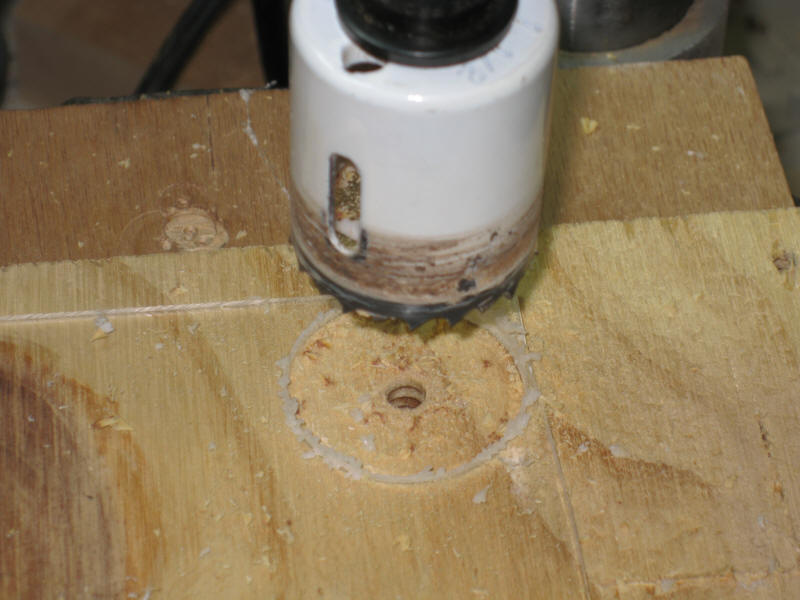
Cut the disks with a 1 1/2" hole saw
.
Back up the Plexiglas with wood when you cut out the
disks. A drill press makes the process much easier!
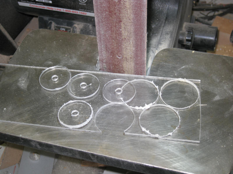
After the disks are cut a belt sander or a sheet of
sandpaper can be used to clean up the edges.
Before gluing the disks drill two 1/16" holes in one of them.
The ends of the wire that make up the coil will pass through these holes.
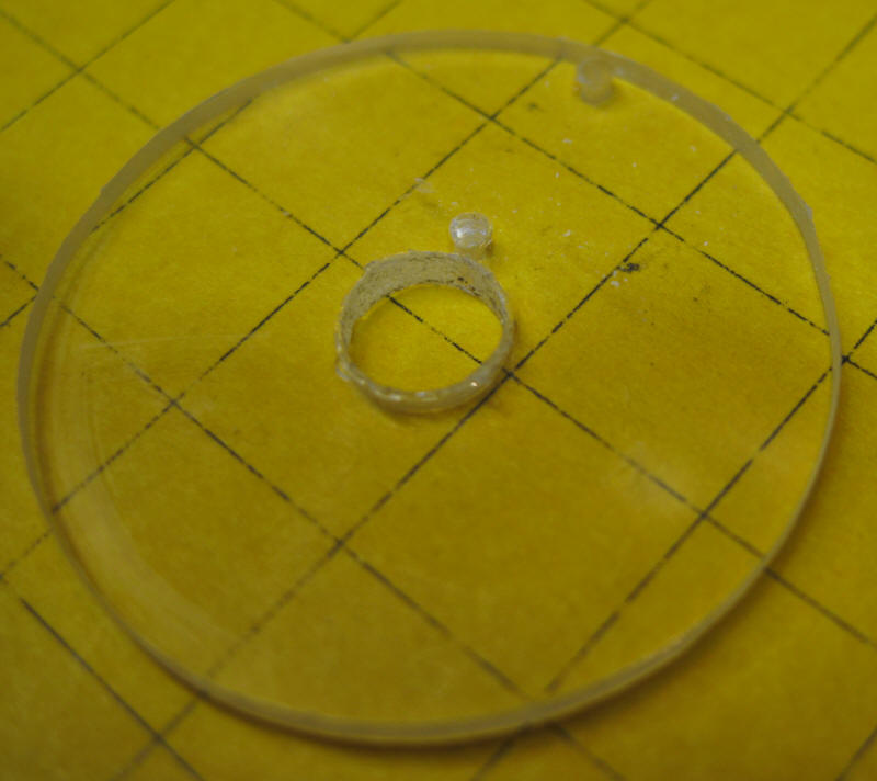
Glue the disks to 1/4" plastic tubing. Carefully align
the disks on the tubing so that they are square and glue them with plastic
glue such as Pro Weld. The spacing between the disks should be close to 3/8" as shown
here.
Winding the Coil
The coil can be wound by hand but it is much, much faster to
do it with a motor. I used a small DC motor that I found
in my junk box. Try to find a motor with a shaft that will fit tightly
into the 1/4" plastic tubing at the center of the coil form. I turned
down the shaft on the motor shown here to get a proper fit. If the
shaft is too small you could build up the
shaft diameter with pieces of brass or plastic tubing.
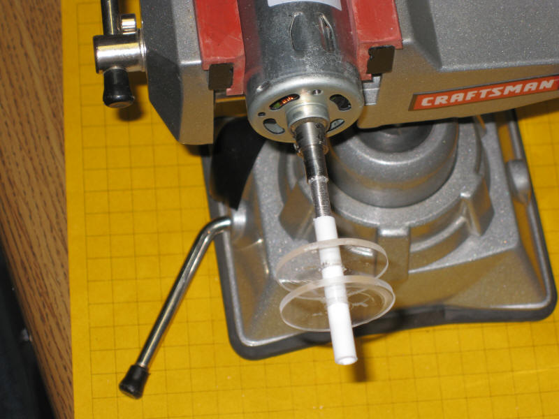
Here the motor is shown mounted in a small vise. The
coil form is mounted on the shaft. Note that the 1/4" tubing extends
from both sides of the coil form. This makes it easier to wind the
coil. The section of tubing that extends from the disk without the
1/16" holes will be cut off when the coil is complete.
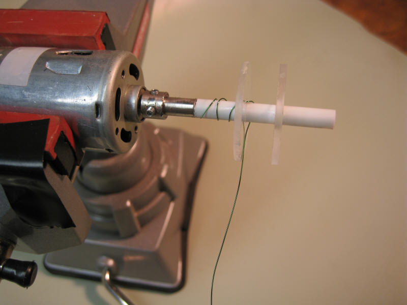
Push a 4" piece of the magnet wire through the inner hole
that you drilled in
one of the disks and wind it around the shaft. Put a piece of tape
around the shaft and onto the motor's shaft to hold the form to the motor.
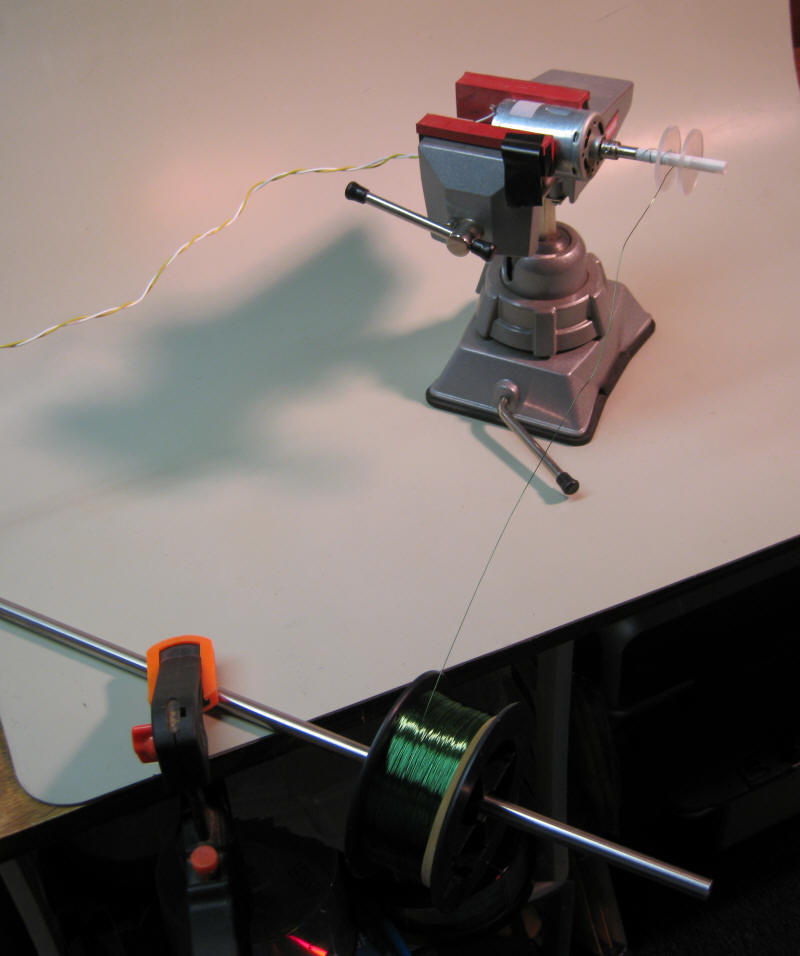
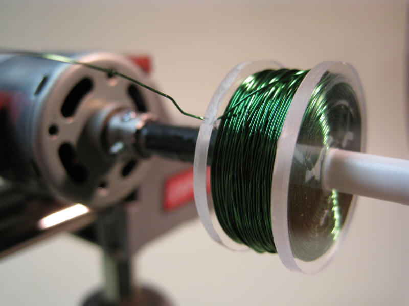
This is the motorized winding unit that was used to make the
coil. The motor is in the vise and the coil of magnet wire is on a
shaft below it. The motor is powered by a few AA cells wired in
series. Keep the voltage low enough so that you can stall the motor
by holding back on the wire.
The video shows how quickly the coil can be wound.
Tension was kept on the wire as the coil form rotated.
The first few rows were turned by hand then the power was
turned on and the rest of the coil took form in short order. It is
very difficult to wind the coil perfectly when doing it by hand. Just
try to keep the winding as even as possible so that the maximum amount of
wire is wound on the form.
When the coil form was nearly full the power was turned off
but the wire was kept under tension so that the newly wound coil and the feed coil
didn't unwind.
(right click the box below and select
PLAY)
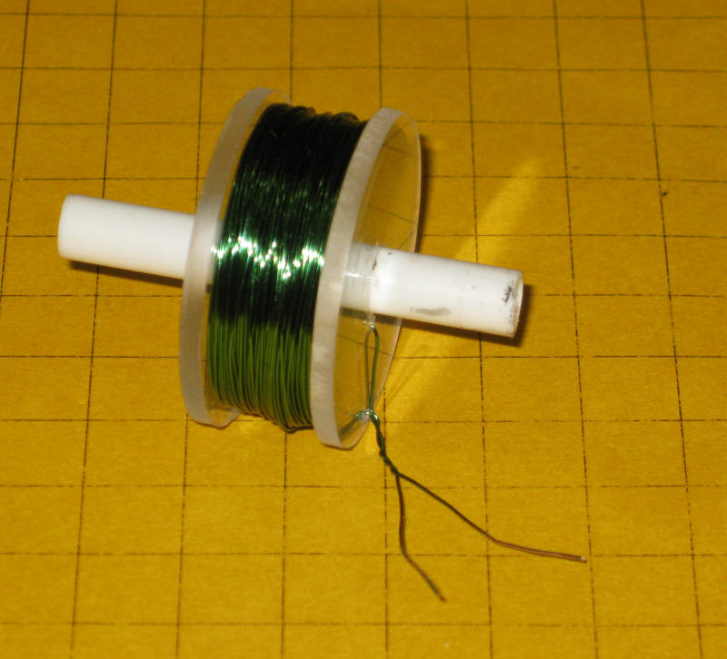
After the coil is wound cut the magnet wire a few inches
from the coil and pull the end of the wire
through the outer hole in the form. Don't kink the wire and make sure that you keep the coil
under tension until this is done or it will surely unwind itself.
Twist the two ends of the wire together and scrape or
sandpaper the
varnish off of the ends of each wire so that it can be soldered to stranded
wire. At this point I like to measure the resistance through the coil.
Put an ohm meter across the two leads. The resistance should be about
10 ohms. If it shows that the coil is open try removing more of the
varnish from the wire.
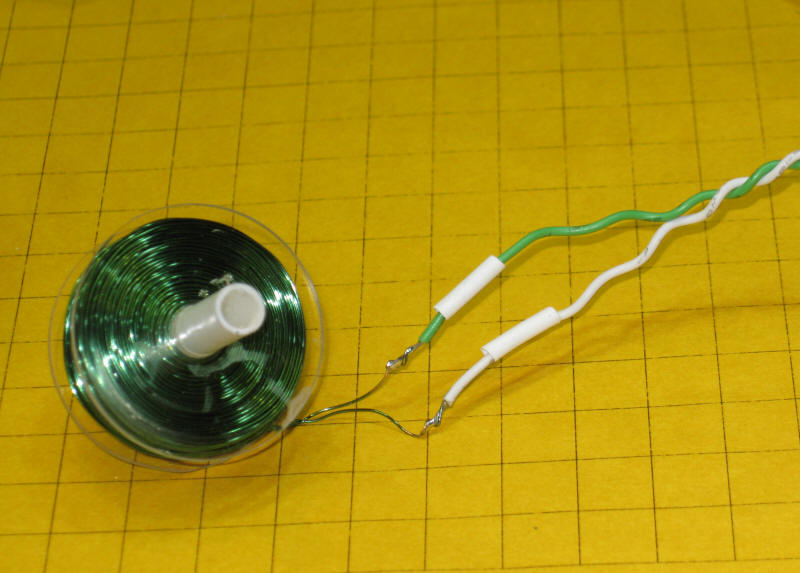
The green and white wire is stranded and better able to take
abuse. It is soldered to the magnet wire and insulated by small pieces
of heat shrink tubing.
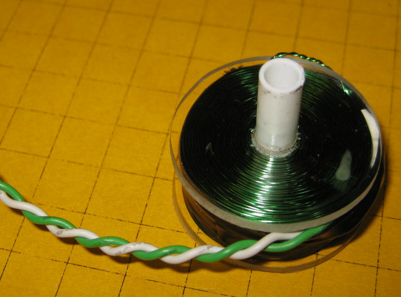
Here is the completed coil. Only the section of the 1/4" tubing
that is on the side with the 1/16" holes remains. The other end was
cut off flush with the outer plastic disk.
The Circuit
The circuit uses a few common parts:
NPN transistor (2N2222 or 2N3904) - Radio Shack
276-1617 or 276-2016
PNP transistor (2N3906) - Radio Shack 276-1604
Diode (1N4003) - Radio Shack 276-1102 - almost any diode
will work
Resistor - 100K - Radio Shack 271-1347
Resistor - 1 Meg - Radio Shack 271-1356
LED (must light on 2 or fewer volts - yellow and red work
well) - Radio Shack 276-021 or similar
Battery (2 AA alkaline cells or 3 AA NiMH cells)
The schematic shows the connections between components.
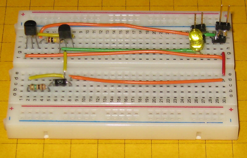
The simplest way to put the circuit together for testing is to
use a prototyping board like the one shown here.
Radio Shack sells a similar board, # 276-003. Make sure
that the two transistors, the LED and the diode are oriented as shown. The
transistor's flat side goes towards the center of the board, the LED's flat side
and the diode's band both go to the left.
Here is a photo of the wiring shown above.
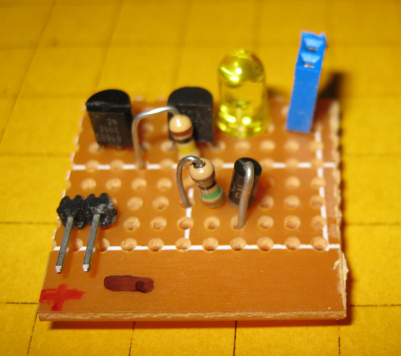
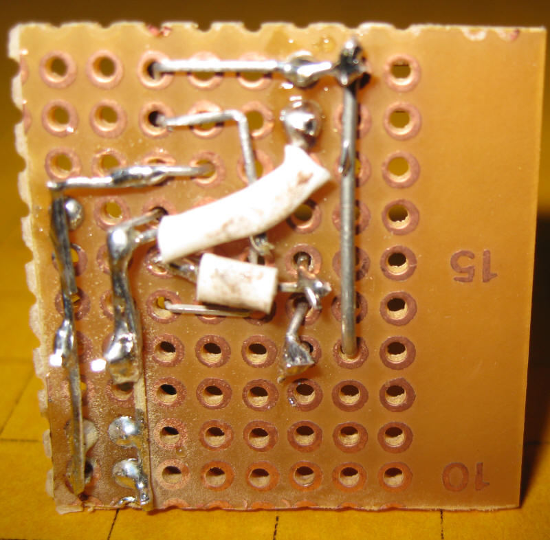
Once everything is working properly the circuit can be soldered
onto a piece of perfboard like Radio Shack's #267-1395.
The bottom of the board holds most of the connections.
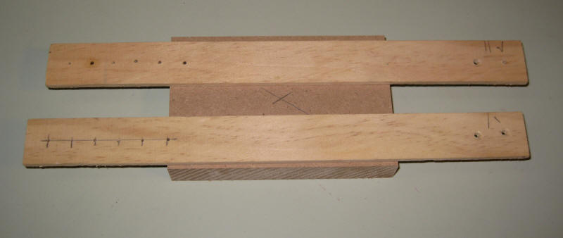
The Base and Horizontal Bar
The base for the test unit is made from plywood or MDF (medium density fiberboard) about 5" x 3" and the
vertical sections are made from 1" x 12" x 1/8" wood strips.
The base should be fairly heavy to keep the unit from rocking as the pendulum
swings. A number of holes were drilled towards the top to accommodate
different sized pendulums.
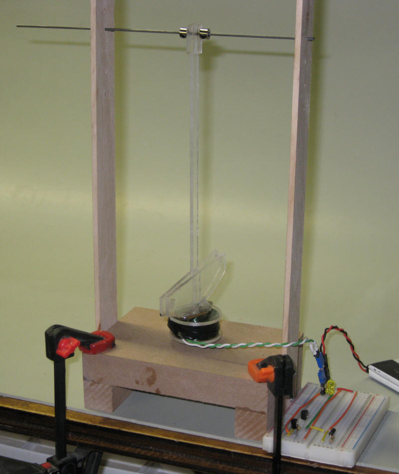
The horizontal bar is made from a 6" piece of 1/16" diameter piano wire.
It goes through holes in the wood uprights and securely supports the pendulum.
The silver pieces on each side of the top of the pendulum are stops that I got
in the model airplane section of the local hobby shop.
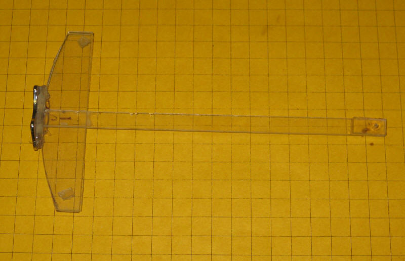
The Pendulum
I made my pendulum from Plexiglas but it could be made from wood, brass or any
other non-ferrous material. Any convenient size can be used. Mine is
about 7" long.
I put small pieces of Plexiglas on either side
of the top of of the pendulum to increase the area where the rod supports it
thinking that it would wear more slowly. It creates a bit more friction
but seems to be worth doing.
The magnet is glued to the bottom of the Plexiglas pendulum.
Magnets
The very bottom of the pendulum contains one or more rare earth magnets. I
have tried a number of different types of magnets and have found that all work
but some work better than others. Some of the best magnets for this
project can be acquired for free.
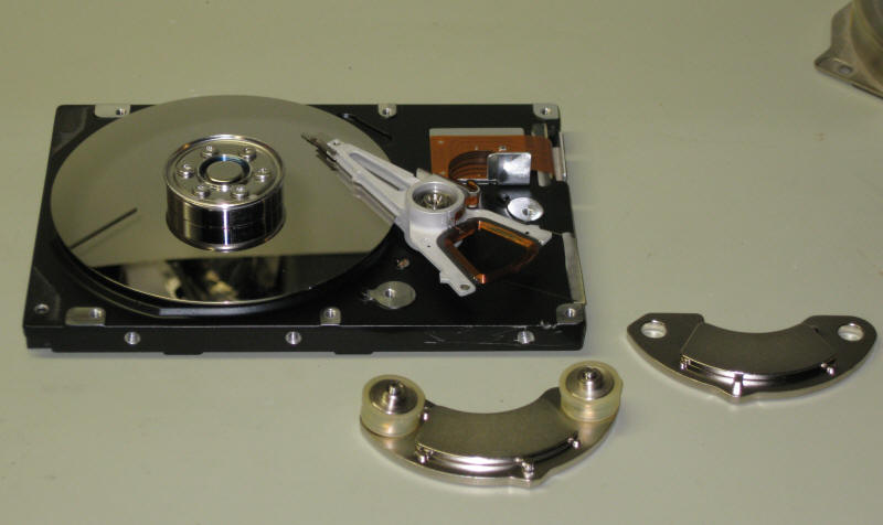
If you have an old computer hard drive that is headed for the scrap pile take a
few minutes to disassemble it and remove the magnet or magnets that are inside.
They are used to move the read/write heads and can be found by the coil end of
the movable heads.
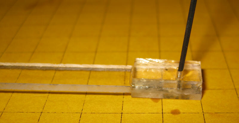
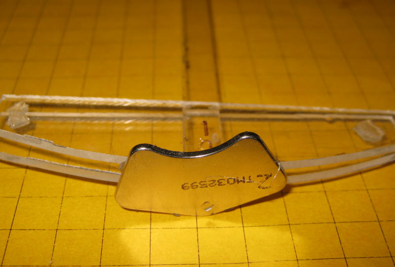
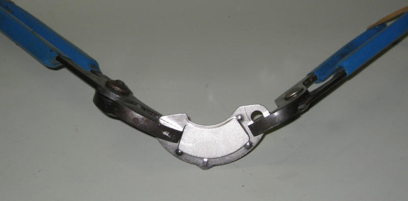
Remove the magnets from the "keepers" by gripping each end of the mount with
pliers and bending down. They will loosen and can easily be removed.
There are also a number of places on the Internet and on eBay that sell magnets.
I vendor that I have used and can recommend is
KJMagnetics.com.
Batteries
The unit will work well with any battery that supplies 3 to 4
volts. I have tested it with 2 fresh alkaline AA cells (3 volts), 3
rechargeable NiMH cells (3.6 volts), a 2032 lithium watch battery and a 3.7 volt lithium ion battery from an old cell
phone. As you increase the voltage the swing of the pendulum will increase
as well. Just be careful not to exceed 5 volts as you reach a point of
diminishing returns and there is a chance that
the components will be damaged.
Testing
Place the pendulum arm, with magnet attached, on the horizontal
rod. Adjust the coil so that the magnet comes as close to it as possible
without hitting. Connect the coil and battery to the circuit board.
Make sure you observe polarity when connecting the battery.
Give the arm a little push and you should see the LED flash
briefly each time the magnet crosses over the coil. The arm should also
start to swing more and more each time it swings. Note that the video
misses a good many of the LED flashes. This is because the LED flashes for
a few thousandths of a second and the frame rate of the video is not sufficient
to catch them all.
(right click the box below and select PLAY)
If the LED does not light check the circuit for proper wiring
and make sure the battery is supplying at least 3 volts. Make sure that
the diode, LED and transistors are oriented correctly.
If the pendulum swings back and forth you can try a few things
to make it swing higher, even making 360 degree loops.
add a more powerful magnet to the bottom of the pendulum or
stack several magnets together
raise the coil closer to the magnet - I place mine within
0.5 mm of the magnet - just enough to clear
increase the battery voltage to 4 or 5 volts
lubricate the pivot point on the pendulum arm where it
rotates on the horizontal bar - the less friction the higher the swing
Gymnast Animation
Once you have gotten the basic pendulum to swing properly you
can move on to making the gymnast animation. The circuit and coil are
identical. Only the support system and the pendulum (gymnast) are changed.
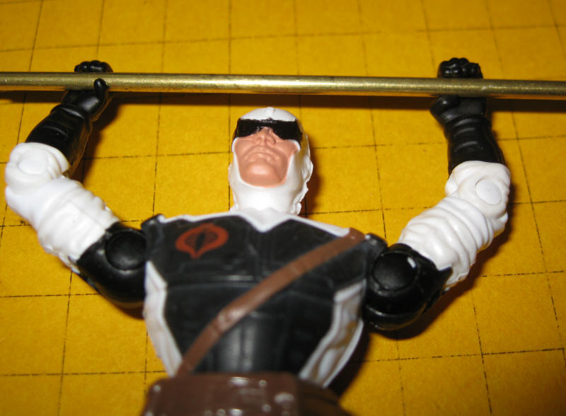
I found a GI Joe figure at the local Dollar General store that
has a number of important features that make it ideal for this project:
the fingers of its hands are bent in a manner that allows
them to grip a bar
the joints are articulated so that the arms can be moved
above the head
the size is acceptable for G-Scale
the price was right: $3.50!
On the negative side it looks nothing like a gymnast but some
paint can take care of that problem!
In order to decrease friction I decided to glue his hands to a
piece of 3/32" brass tubing. The tubing fits right over the piano wire and
provides a very low friction support.
The magnet was glued to his feet and his joints were bent so
that the feet were horizontal when it crosses over the coil.
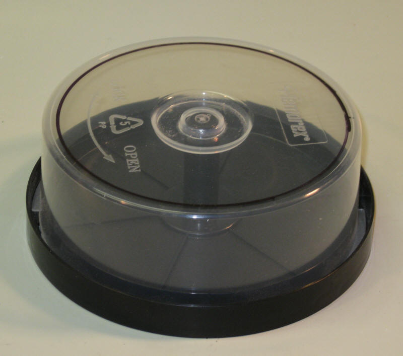
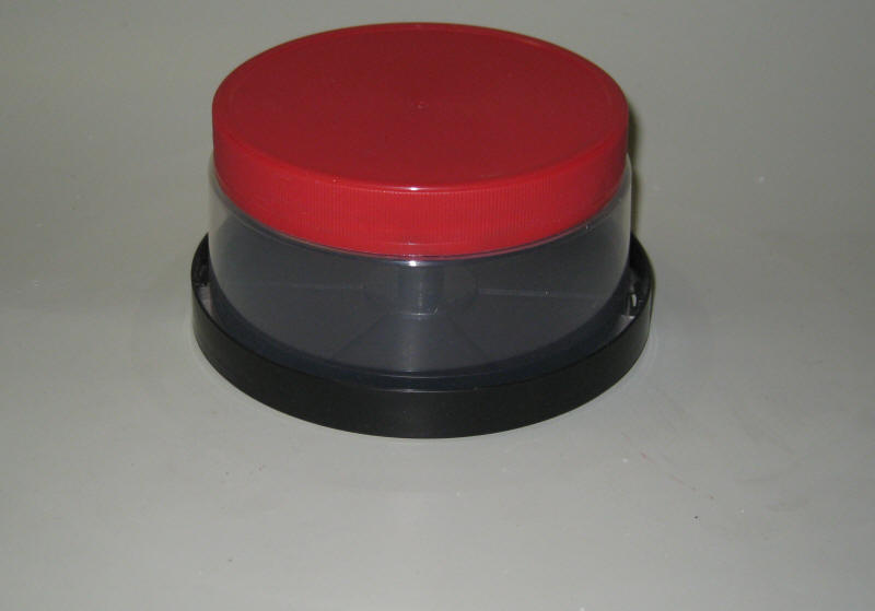
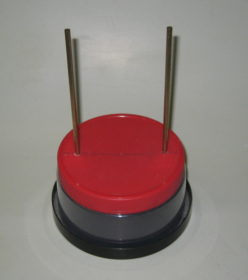
The base of the gymnast's swing was made from a pretzel jar lid
that sits atop an empty DVD / CD container.
The black mark on the top of the CD container shows where the
jar lid fits. The material inside of that mark was removed to give access
to the jar lid.
This photo shows how the top of the CD container was cut away.
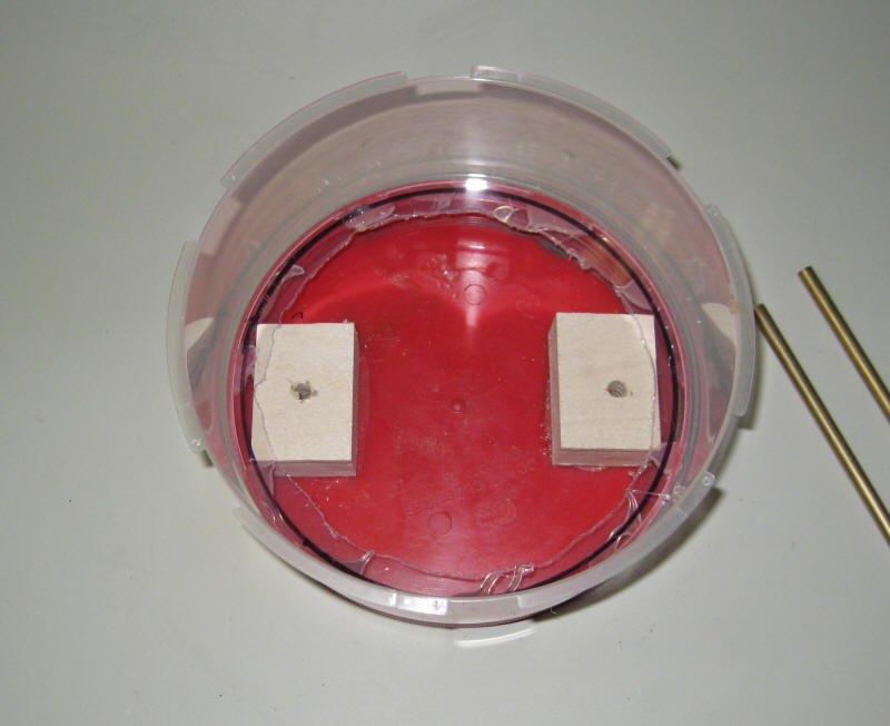
Wood blocks were
glued to the red lid. The lid was drilled to support two 3/16" brass rods
that will make up the vertical supports for the horizontal bar.
The rods are pushed through the holes in the lid and into the
wood blocks below. It may help to ream out the holes a bit so that the
brass rods can be pushed in more easily. Don't make them too tight as you
have to be able to move them in and out of the holes to adjust the position of the gymnast.
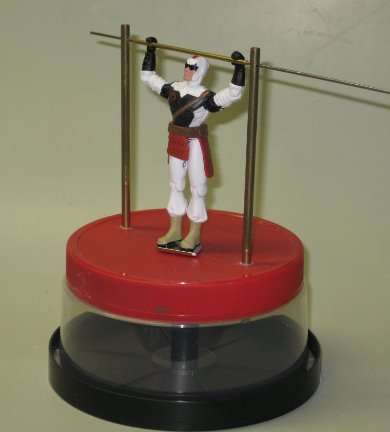
Here the gymnast is supported by the horizontal bar. The
3/32" brass rod between his hands goes over a piece 1/16" steel piano wire.
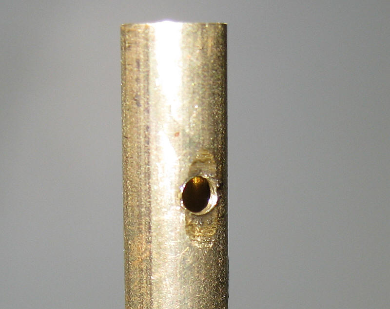
The piano wire goes through 1/16" holes in the vertical brass rods. To
facilitate drilling a hole into round tubing a small area was ground flat before
drilling. To help reduce friction the outer hole in each vertical rod was
drilled out to 3/32" so that the piano wire only contacts the inner hole.
The coil was glued to the bottom side of the lid.
Here is the nearly completed gymnast during a test swing.
(right click the box below and select PLAY)
In this video he is joined by a properly painted team mate who
has been adjusted and lubricated so that his swinging is much more energetic!
His other training secret is to add more magnets to his feet!
(right click the box below and select PLAY)
Give it a Try!
I have to say that this has been one of the most "fun" projects I have
undertaken in some time. More importantly it is something that visitors to
our displays enjoy. Give it a try and make sure you bring the bare bones
version of the pendulum along so that you can use it to explain how it works!
Please let me know if you have any questions or need help.

.jpg)


.jpg)