Reverse Loop Controller
with Double Slip Switch

Revised 04-05-08

The objective of this project is to operate a train through an LGB double slip switch that, along with a standard turnout, can have the train navigate the reverse loop either in a clockwise or counterclockwise direction.


Overview:

A reversing loop is frequently used by model railroaders to reverse an engine's path on a single main line.  The problem with reversing loops crops up when track power is used as they create a short circuit within the track as the loop connects the two rails of the main line.  This problem is addressed in a number of ways.  The simplest and most common is to completely isolate a section of the reversing loop from the main line.  This isolated section must be long enough to accommodate the engine and any cars that might have pickup wheels that feed power to the engine.  The isolated section is powered from the main line through a bridge rectifier.  This device supplies the same polarity of power regardless of the polarity that is fed into it.

When the train has fully entered the reversing loop a reed switch is tripped by a magnet under the engine triggering the controller which throws the DPDT relay reversing the power to the main line so that the train moves in the proper direction upon exiting the reversing loop.  An optical sensor can be used in place of the reed relay and magnet with additional circuitry.

Layout:

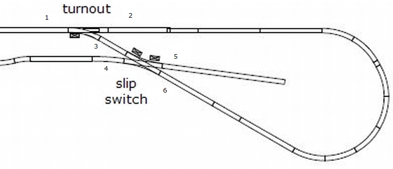
The layout is shown here.  The crossover at the left presents no wiring problems and simply changes the train's direction after it completes the loop.


This detail shows the right hand section of the layout.  There are a number of scenarios that must be accommodated:
  1. Train on upper track moving from left to right - turnout set to go from "1" to "2" and slip switch set to "6" to "4" - the train enters the loop (clockwise) and exits on the lower track.  Nothing needs to be done with polarity as no short circuits exit.
  2. Train on upper track moving from left to right - turnout set to go from "1" to "2" and slip switch set to "6" to "3" - the train enters the loop (clockwise) and exits on the same track that it came in on.  This is a classic reverse loop and a short circuit must be prevented by reversing the polarity at some point when the train is in the loop.
  3. Train on upper track moving from left to right - turnout set to go from "1" to "3" and slip switch set to "3" to "6" -  the train enters the loop (counterclockwise) and exits on the same track that it came in on.  This is a classic reverse loop and a short circuit must be prevented by reversing the polarity at some point when the train is in the loop.  Most turnouts will allow a train to go through the turnout from "2" to "1" without the switch being set that way so no automatic operation of the turnout (setting it from "2" to "1") is necessary.
  4. Train on the lower track moving from left to right - slip switch set to "4" to "5" - the train enters the siding
  5. Train on the lower track moving from left to right - slip switch set to "4" to "6" -the train enters the loop (counterclockwise) and exits on the upper track.  Nothing needs to be done with polarity as no short circuits exist.  Most turnouts will allow a train to go through the turnout from "2" to "1" without the switch being set that way so no automatic operation of the turnout (setting it from "2" to "1") is necessary.