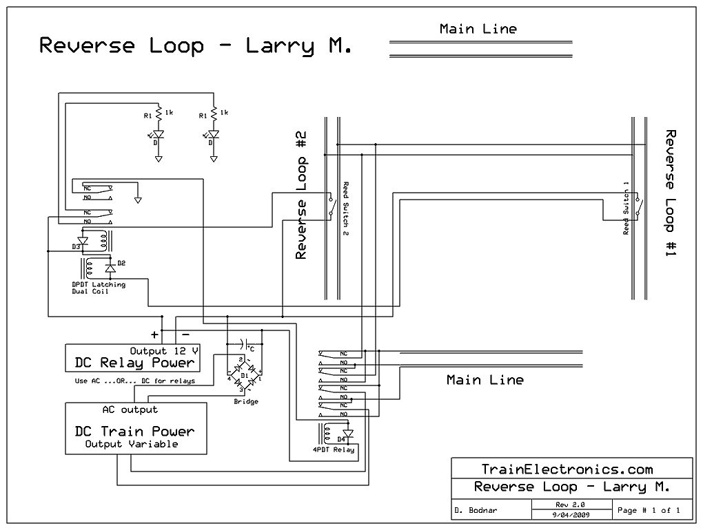
| Overview: A reversing loop is frequently used by model railroaders to reverse an engine's path on a single main line. The problem with reversing loops crops up when track power is used as they create a short circuit within the track as the loop connects the two rails of the main line. This problem is addressed in a number of ways. The simplest and most common is to completely isolate a section of the reversing loop from the main line. This isolated section must be long enough to accommodate the engine and any cars that might have pickup wheels that feed power to the engine. The isolated section is powered from the main line through a bridge rectifier. This device supplies the same polarity of power regardless of the polarity that is fed into it. When the train has fully entered the reversing loop a reed switch is tripped by a magnet under the engine triggering the controller which throws the DPDT relay reversing the power to the main line so that the train moves in the proper direction upon exiting the reversing loop. An optical sensor can be used in place of the reed relay and magnet with additional circuitry. Unfortunately this option will not work in this case as the train can go into the reverse loop in either direction. The following information will help in designing a solution to this problem. |
|||||||
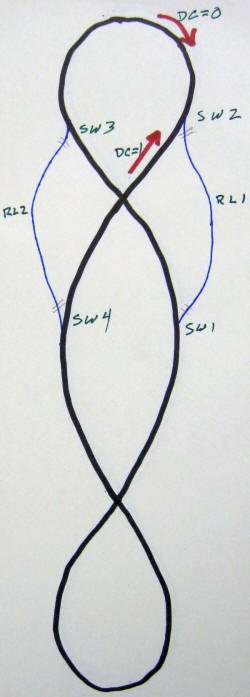
| Layout:
The layout is shown here. The mainline is
in black and the two reverse loops are in blue. The crossovers
at the top and bottom present no wiring problems. There are
four switches, labeled SW1, SW2, SW3 and SW4. The reverse
loops are labeled RL1 and RL2. The red arrows show the
direction that the train will run when the DC polarity is set one
way (represented by DC=0) or the other way (represented by DC=1).
The double hash marks (=) indicate places where the track is
completely isolated from the main line.
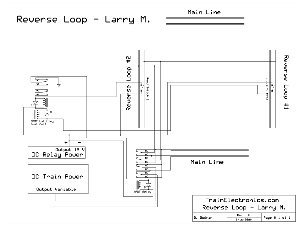
Schematic:
|
|||||||
|
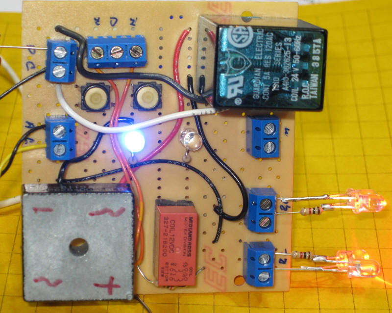
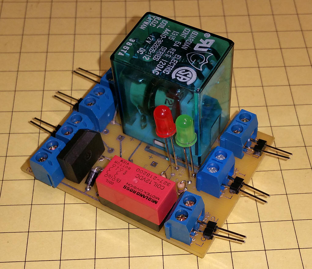
Completed Unit The controller was constructed on a prototyping board. The primary relay is in the upper right with the latching relay bottom center (the orange object). DC power and AC from the power supply connect on the left. The two reed switches connect top center with the center contact being a common connection. The two small round objects below the reed switch terminals are test buttons that simulate the reed switches being hit. The two LEDs (one is on in the center) indicate the state of the relay. One is blue and one is green. The main line connects just below the relay and the two reverse loops go to the two pairs of terminals below it. The LEDs in the lower right are for testing.
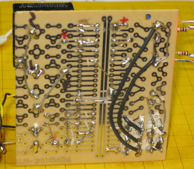
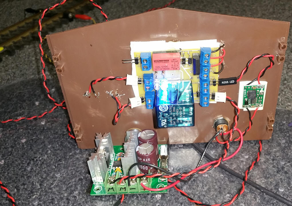
The rear view shows the wiring.
|
|||||||
| Revised schematic which was made into a
circuit board.
|