| The Phoenix 2K2 sound cards can be easily interfaced to Aristo
Craft's Revolution receiver so that two of the auxiliary control
buttons can increase or decrease the sound unit's volume. The newer Phoenix sound card, the PB9, uses a different method of adjusting volume and needs an interface board so that the Revolution can control volume. |
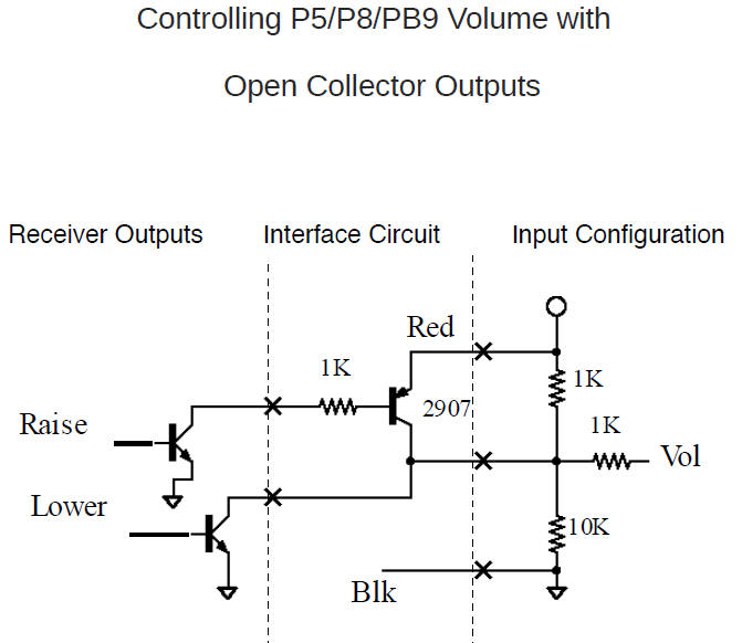
| The Revolution's six auxiliary outputs are "open collector"
outputs that pull the output pin to ground when activated.
The Phoenix sound card's volume adjust pin is pulled low (to ground) or pulled high (to +5 volts) to change the volume. The interface changes the open collector outputs on the Revolution so that they can apply the proper voltage to the volume adjust pin. |
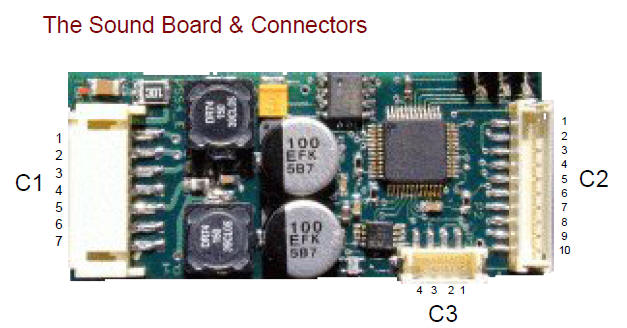
| PB9 Volume Connections
|
||||||||||||
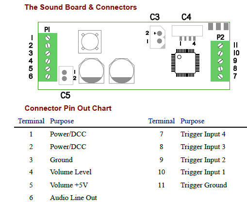
| P5 Volume Connections
|
||||||||||||
| This schematic is the one from Phoenix.
|
||||||||||||
| This schematic is just my reproduction of the Phoenix schematic.
Note that the transistor is a 2N3906 rather than the recommended
2907. Internally they are almost identical. Parts:
|
||||||||||||
Results with this circuit:
|
||||||||||||
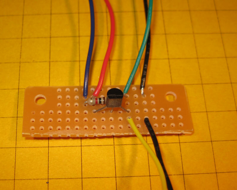
| Construction This circuit is so simple that construction on a piece of prototyping board should only take a few minutes.
|
||||||||||||
| Making Connections
|
||||||||||||
The four wires at the bottom of the photo go to:
The two wires at the top of the photo go to:
In the description above I used the blue and green wires from the auxiliary interface - that allows you to increase or decrease the volume with buttons 1 and 2. If you want to use two other buttons simply use two other wires from the auxiliary interface. Note that the black wire to the Phoenix card may not be necessary and could cause a ground loop. If you experience any problems try removing it. ------------------------------------------------------------------------------------------------------------------------------------------------ The completed, trimmed board is shown here:
|
.jpg)
.jpg)
.jpg)
.jpg)