A Simple, Inexpensive
Servo Controller
d. bodnar 04-01-2016
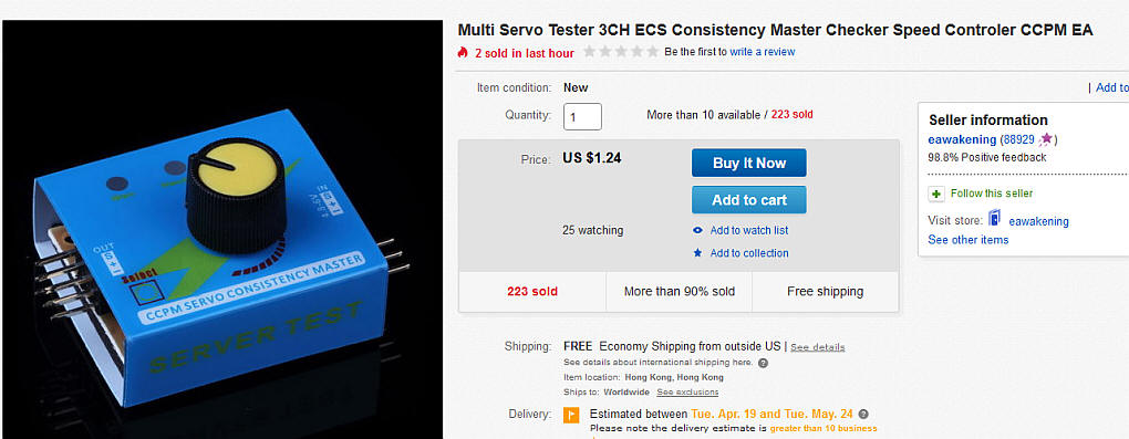
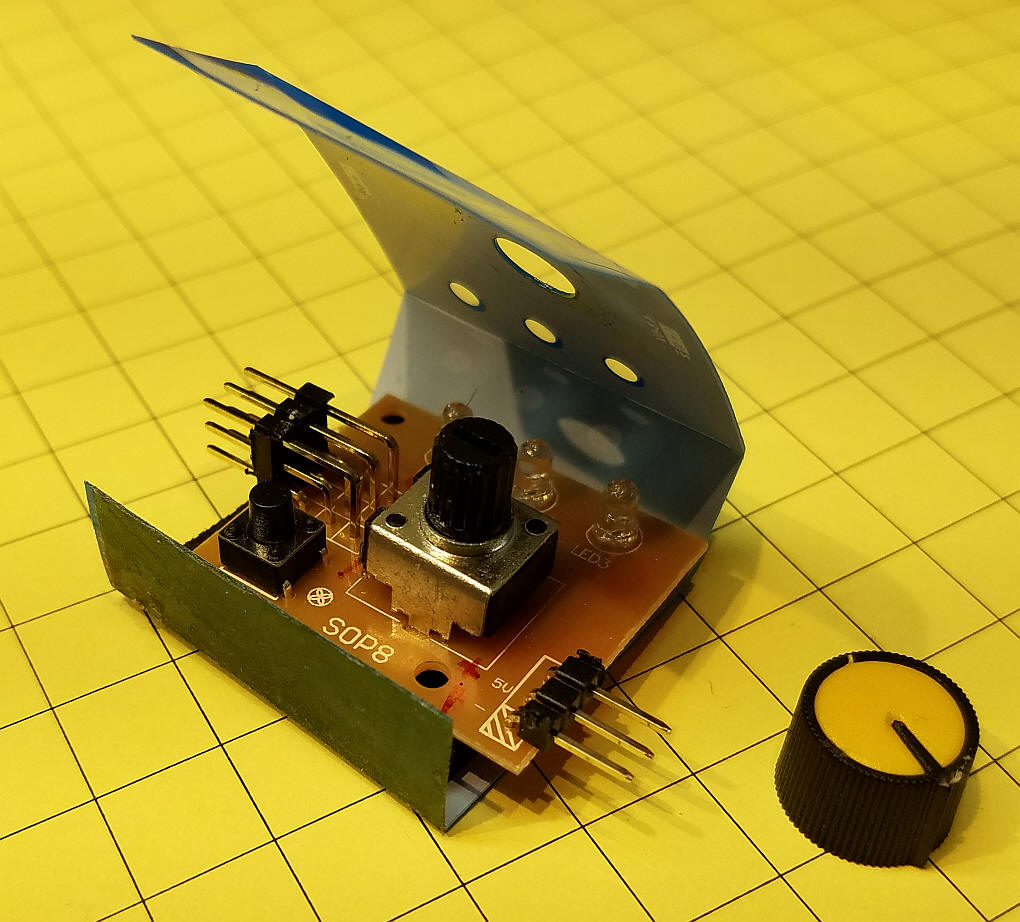
| Introduction Recently a member of our local railroad club asked me about using small servos to control the switches (turnouts) on his modular layout. He knew that I used them on my module and that they have worked reliably for a number of years (see: http://www.trainelectronics.com/Module/ ) I built up a sample PIC microcontroller based controller and showed him how it worked. It operated the servo as expected but there is a significant cost associated with controlling servos with a PIC, Arduino or other microcontroller, especially if you need to control a number of servos. Coincidentally I came across a very small servo testing unit (see top photo) on eBay right after I showed the PIC controller to my friend. The price was certainly right (see eBay listing below) as the controllers are only $1.24 each INCLUDING SHIPPING!
I ordered a few for evaluation. As you will see in the rest of this article I found that the controllers were not only good for testing servos but, with the addition of a single resistor and a switch, could be used to control servos on switches on the railroad. |
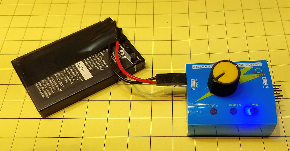
| Controller Operation The controller has three connection pins on one end, three sets of three connection pins on the other side, a potentiometer on top and a hidden push button switch under the cover. There are three LEDs that show the mode of operation that has been chosen. To operate the controller connect a DC voltage between 3.5 and 6 volts to the two pins in the single set of three. The positive connection goes to the pin in the center and the negative connection to the pin closest to the edge of the circuit board. In this photo the controller is connected to a 3.7 volt cell phone battery. There is a label on the case of the controller that indicates which pin is positive and which is negative but, for some reason, it was not over the pins on the units that I tested.
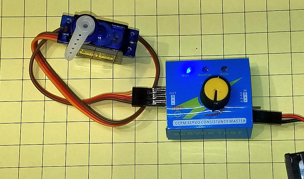
Connect the servo's three pin cable to one of the three sets of pins on the other side of the controller. The negative wire from the servo (usually colored brown or black) goes to the pin marked with a minus (-) sign.
When power is connected to the controller the first blue LED lights under the label that reads "Man" (for manual). In this mode turning the knob on the potentiometer turns the servo's horn. The servo rotates about 90 degrees, roughly 1/2 of its maximum rotation. The other two modes ("Neutral" and "Auto") are selected by pressing on the case over the area labeled "Select" - there is a small pushbutton under that area that changes the mode.
In Neutral mode the servo is always placed in its middle position. When in Auto the servo is moved from one extreme to the other every second or two. The Auto mode is great for testing or burning in a new servo. The potentiometer does not change anything in the second two modes. One, two or three servos can be connected to the test pins at the same time. |
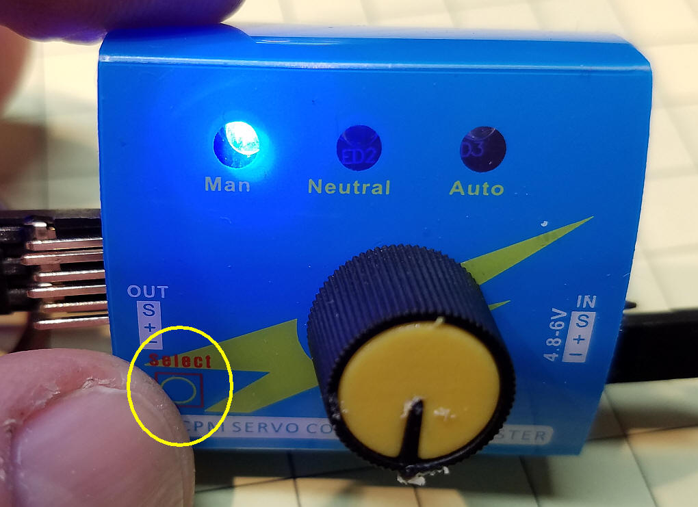
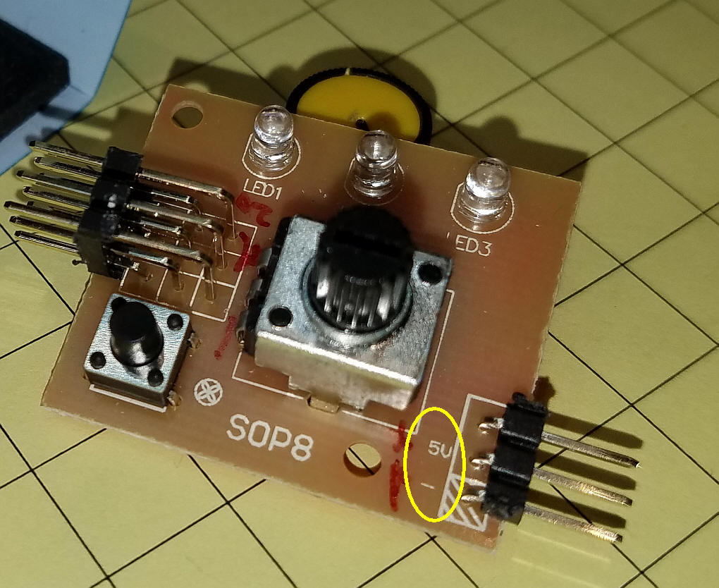
| What's Inside? Removing the plastic sheet that makes up the case is simply a matter of pulling off the knob on the potentiometer and separating the overlapping part of the case under the words "SERVER TEST"
If you look carefully you will see that the two pins that get power are marked 5V and - (see area circled in yellow)
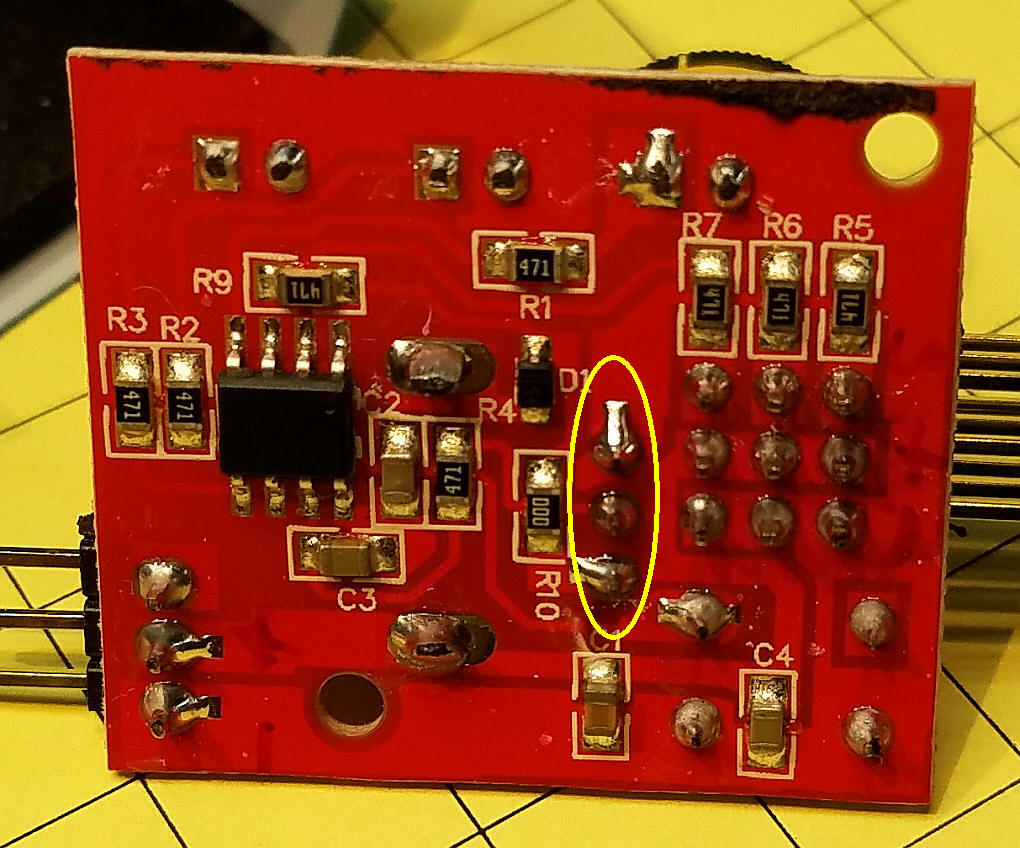
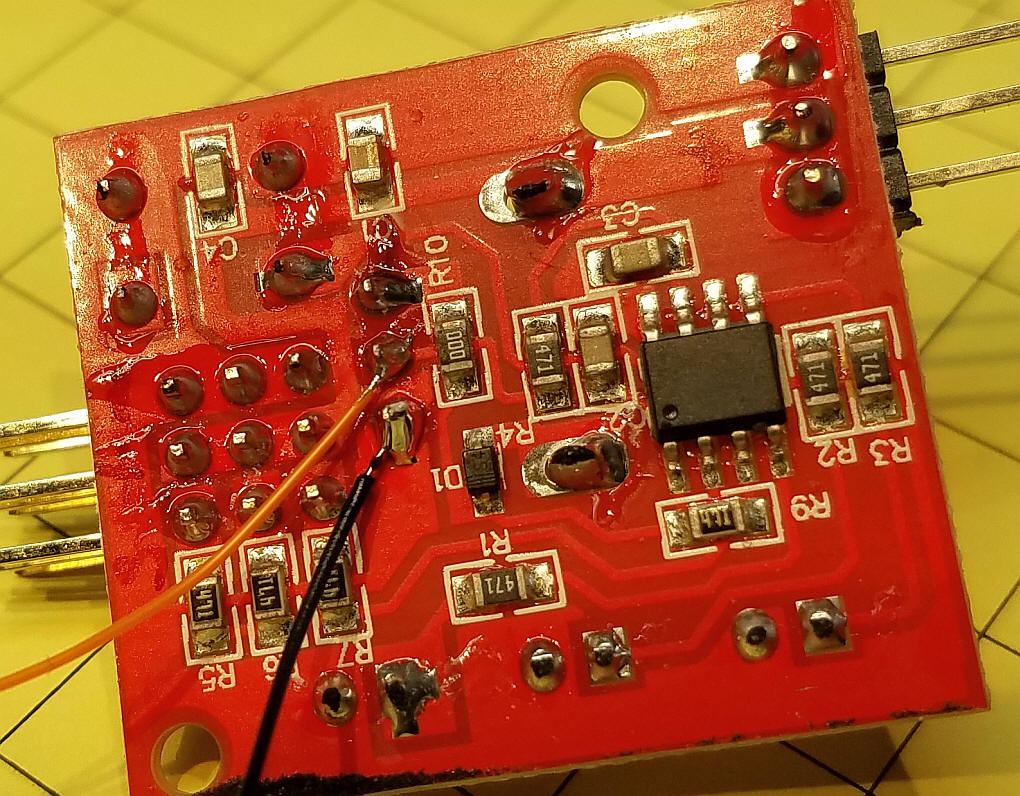
The underside of the board contains a microcontroller (the 8 pin device left of center) and a number of surface mount capacitors and resistors. The three pins circled connect to the potentiometer.
|
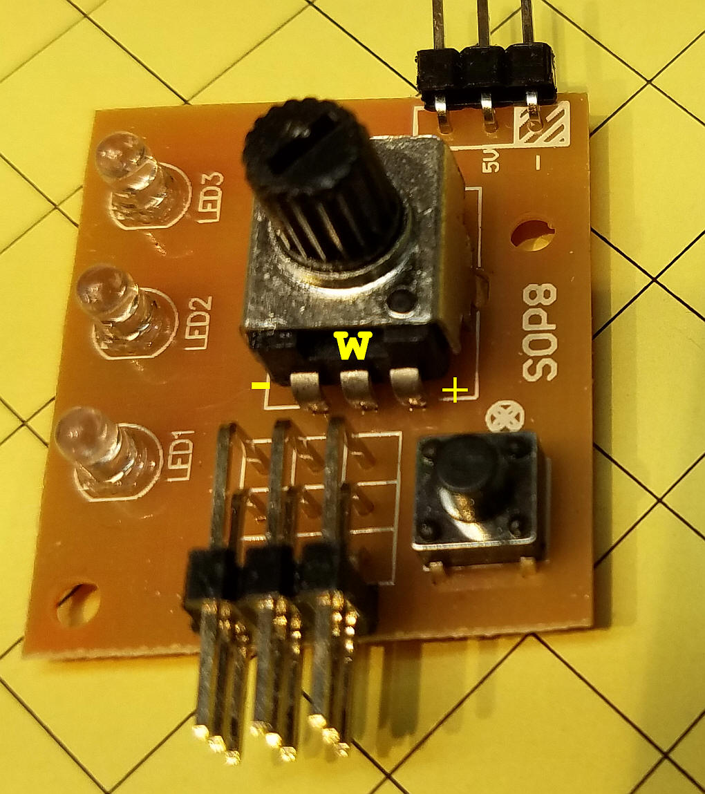
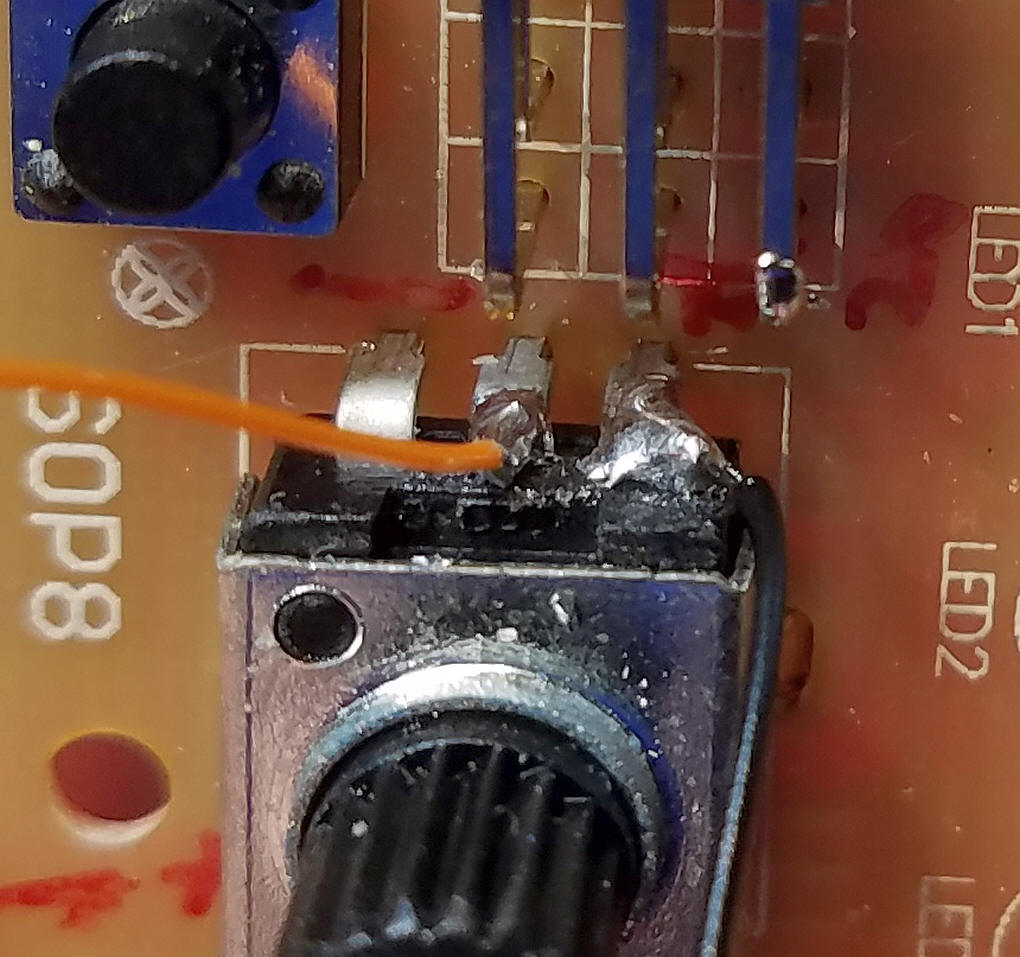
| Modifying for Limited Movement The servo control board can be used to operate a servo that moves the points on a switch. Unfortunately the controller can easily move the servo much more than is needed to throw the switch, causing damage to it. While you could use a physical stop that would limit the potentiometer's movement to what is needed to operate the switch servo I thought it would be better to look for a way to modify the circuit so that it would be unable to move the points farther than needed. I spent some time examining the board and noted that the potentiometer is wired as a simple voltage divider that delivers a voltage between 0 volts and 5 volts to a pin on the microcontroller. In the photo below the three pins attached to the potentiometer are shown. The pin to the left is connected to ground (negative power connection), the pin to the right is connected to 5 volts (or whatever the power supply provides) and the center pin connects to a wiper inside of the potentiometer that moves as the knob is turned. When the knob is all the way to the left (counter clockwise) the pin on the microcontroller that is connected to the wiper sees 0 volts. When it is turned all the way to the right it sees 5 volts. Positions in-between the extremes deliver a voltage between 0 and 5 volts. This variable voltage determines the position of the servo.
This diagram shows how the pot (potentiometer) is wired to the circuit. The arrow that represents the wiper moves from side to side delivering a voltage that is proportional to its position between 0 volts (ground) and 5 volts.
This method of operation gave me an idea that might allow a simple modification to the board that would limit the servo's movement to a range that would be appropriate for switches. If I could insert a resistor in the circuit that would restrict the range of voltage that the potentiometer delivers it would keep the servo from moving outside of the range of what was needed. Compare the diagram above with the one below. You will see that two components have been added, a switch (SPST) and a 4.7K resistor. You could also use a 10K potentiometer to replace the 4.7 K resistor during testing. Just wire to the center and one of the other pins. After you get the movement range you need just remove the potentiometer and measure the resistance between those pins to select your resistor. If the switch is open the resistor is not connected to ground and the servo controller operates as it normally does. With the switch open adjust the potentiometer so that the points on the switch are at one extreme. Close the switch and you will see the points move to the other extreme. If the points don't move open the switch and adjust the pot so that the points are on the other side of the switch. If the movement is too great use a larger value resistor, if it is not enough use a smaller value. This procedure is shown in the video.
|
| Wiring the Modification The wiring is quite simple. Two wires are soldered to the potentiometer's wiper (center lead) and the potentiometer pin that connects to ground. The black wire below goes to the ground side of the pot and the orange to the center lead.
If you prefer you can solder to the leads on top of the board. First tin each pin with a drop of solder then solder on the wires.
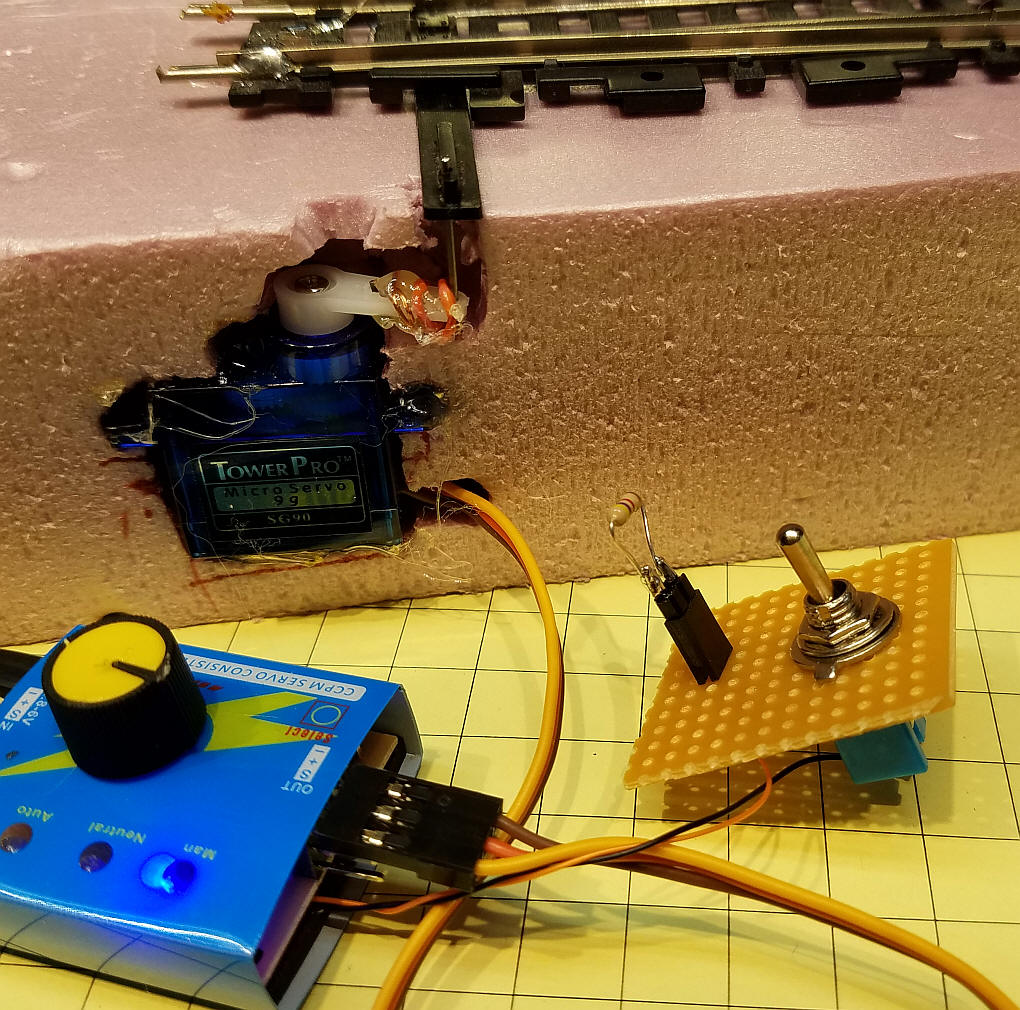
My test setup is shown here. The servo is mounted in a piece of foam and connected to the switch throw arm with a small piece of piano wire. The switch and resistor are mounted on a small piece of circuit board. The resistor plugs into a socket so that I can easily swap out resistors for testing.
|