Station Stop Controller
revised 04-07-09
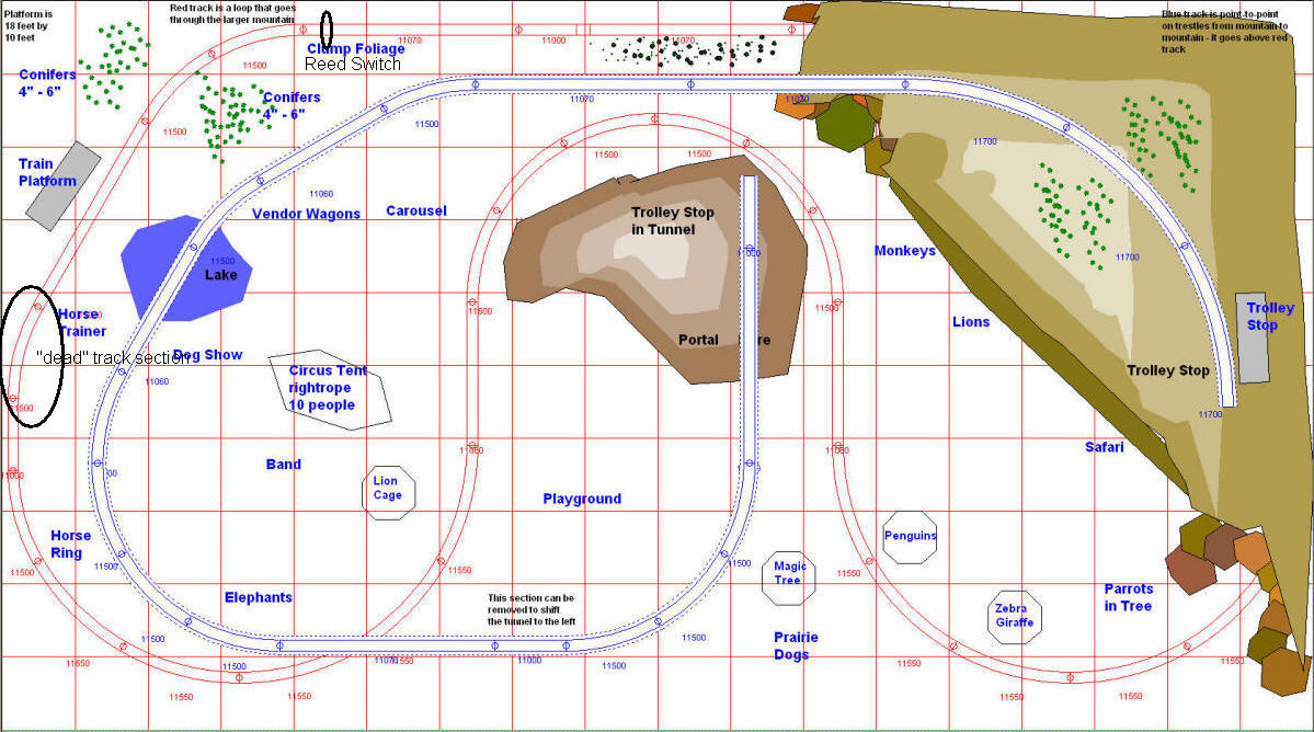
| Design considerations: The train on the main line at the Pittsburgh Children's Hospital layout starts running when a visitor presses a button. This starts a timer that activates the train for several minutes. The train runs in a counter clockwise direction and needs to stop at the station platform (seen in the upper left in the diagram below) at the end of each of its timed runs. A number of circuits were considered to accomplish this task. The final design uses a combination of relays, diodes and a microcontroller. At the end of each trip around and around the layout these components decelerate the train as it approaches the station platform, stops it at the station and, when activated again, gradually accelerates it as it leaves the station. The section of track that is directly in front of the train platform has one rail isolated from the rest of the layout. That allows us to remove power from it bringing the train to a stop. Three sections of track on either side of that section are also isolated with the cut rails joined by diodes. Since each diode wired in series with a DC current drops the voltage a bit the train will decelerate as it nears the station and accelerate as it pulls away. The schematic shows the wiring in more detail. |
| Circuit: In the schematic the lower rail is cut in 8 places. The gaps on either side of the section labeled "isolated track" are bridged by one or more diodes. The diodes are connected in pairs, wired back to back. This allows the train to run in either direction. As the train enters the first cut section the diodes drop the voltage to the track. When it hits the second section it drops again as more diodes are added. By the time it reaches the last section its speed has decreased significantly. The train runs normally when the diode relay is not energized as it shorts out the diodes and the second relay applies power to the "isolated track". When the timer signals the microcontroller that the train is to stop the microcontroller begins monitoring the reed switch. Once the train crosses the reed switch the relay contacts close putting the diodes into the circuit and removing power from the isolated section of track. The train slows more as it enters each diode section. When it gets to the isolated track, where power has been completely removed, it stops. When the timer is started the power is first restored to the isolated track. The train slowly enters the adjoining diode section and speeds up as it passes diodes and receives more and more power from the track. After 12 seconds the diode relay again shorts out the diodes so that the train operates unobstructed. |
| Schematic:
|
|
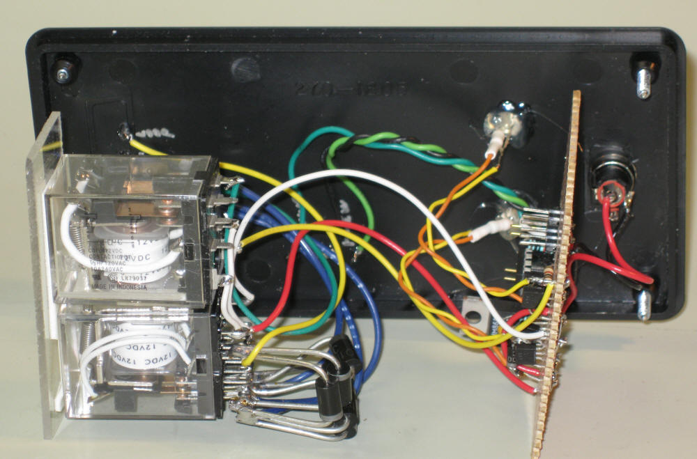
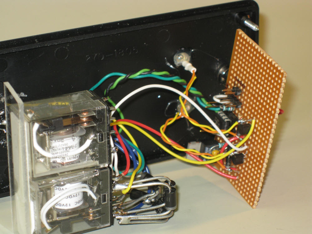
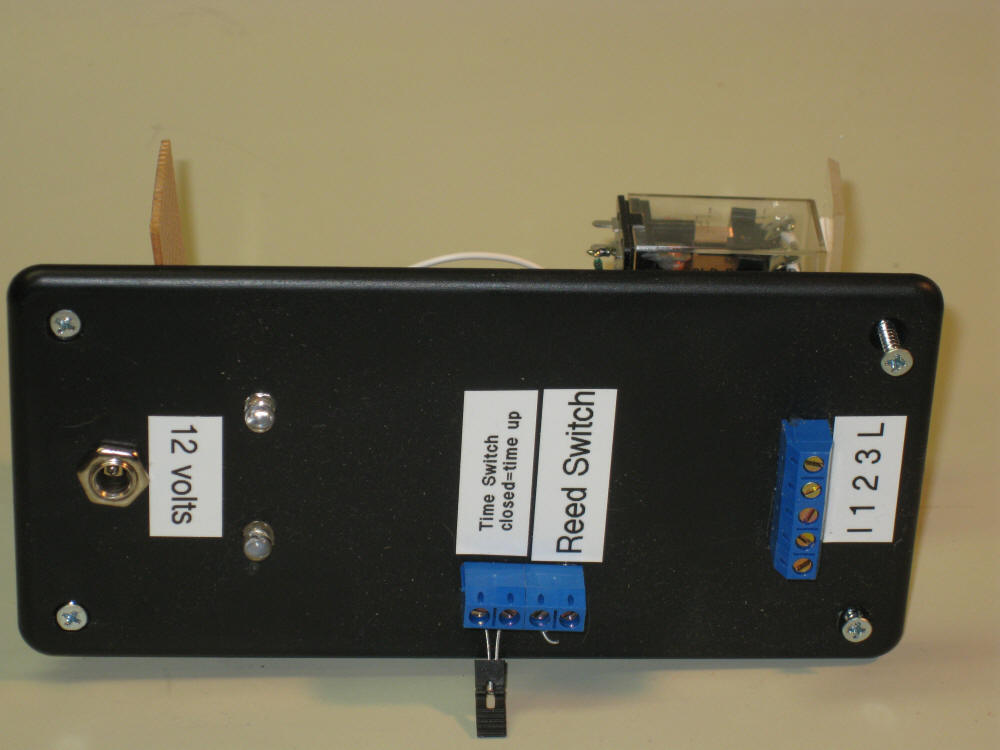
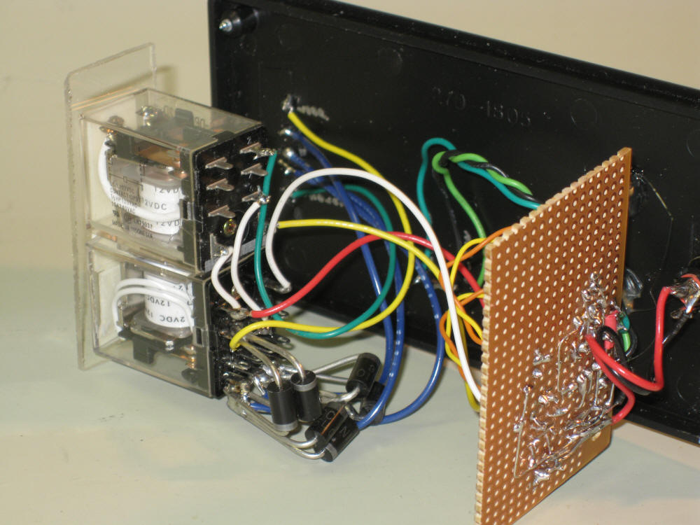
Prototype Photos
| Timer The Station Stop Controller does not include its own internal timer. An external timer is used. This allows us to use a variety of timers should the need arise. The timer we are using initially is based on the BARC auto-reverse controller code. It works as follows:
|
| Code '* Date : 4/13/09 |