Stepper Motors

Revised 1-30-07

The objective of this project is to design and construct a controller that will operate two geared stepper motors so that they can operate a model lift bridge.  One stepper motor will be in each of the bridge's towers. 
When an activation button is pushed the motors will operate together to evenly lift the bridge to a set height.
When the button is pressed again the bridge will return to its lowered position.
While the motors are in motion a relay will be closed activating two SPST normally open switches that will be used to activate sound generating units.


Click here for 16F88 Version


Hardware:

The stepper motors are 6 wire unipolar steppers that are controlled by a TI SN754410NE H-Bridge that is connected to a PIC 16fF84 microcontroller.

The PIC sends pulses to the H-Bridge that move the motor in 1 degree/step increments in either a clockwise or counter clockwise direction.

An infrared detector is used to sense IR pulses sent by the TV remote control

A DPDT relay is used to provide two NO SPST contacts that can be used to activate sounds or other accessories.


Schematic:

Click on this thumbnail to see the schematic

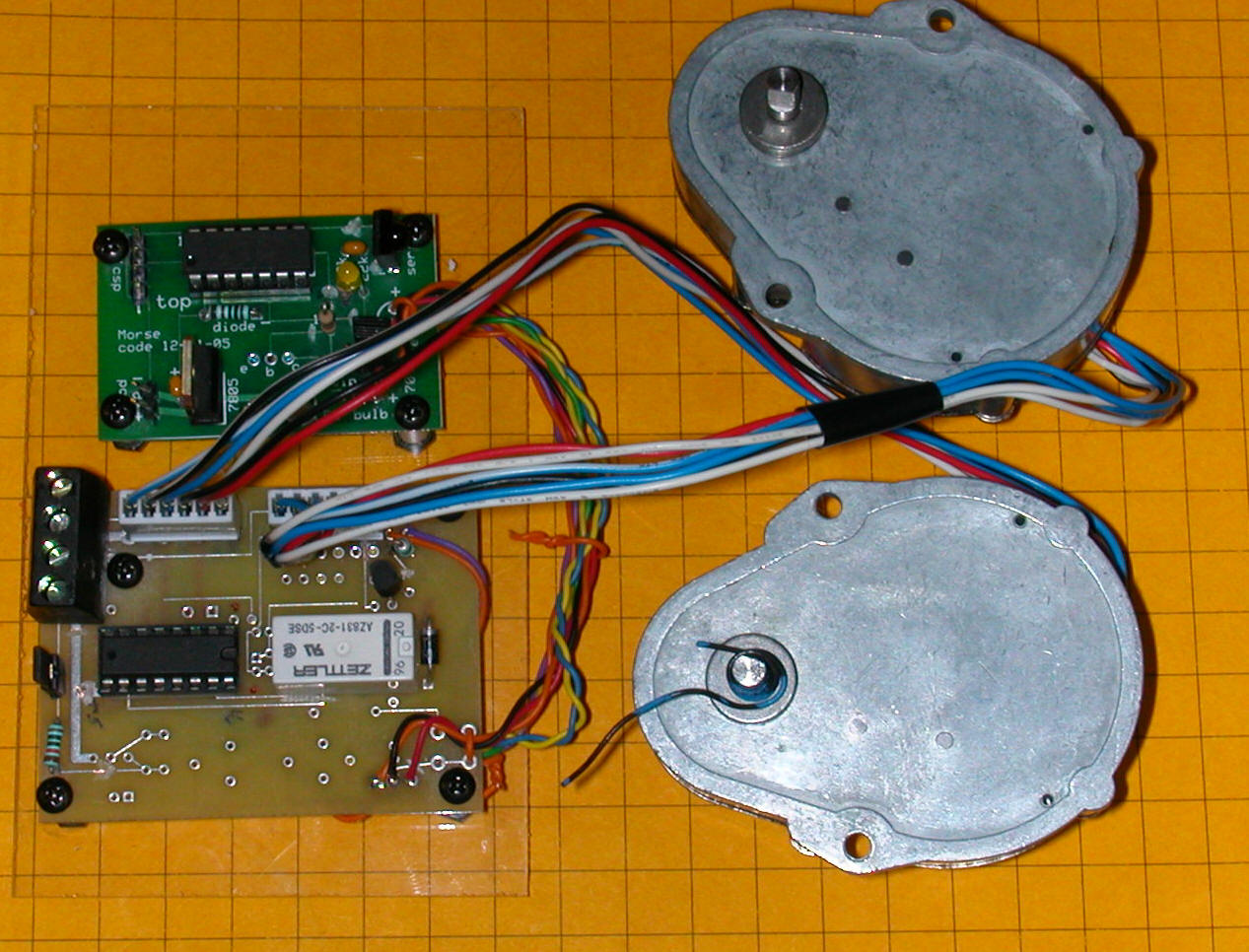
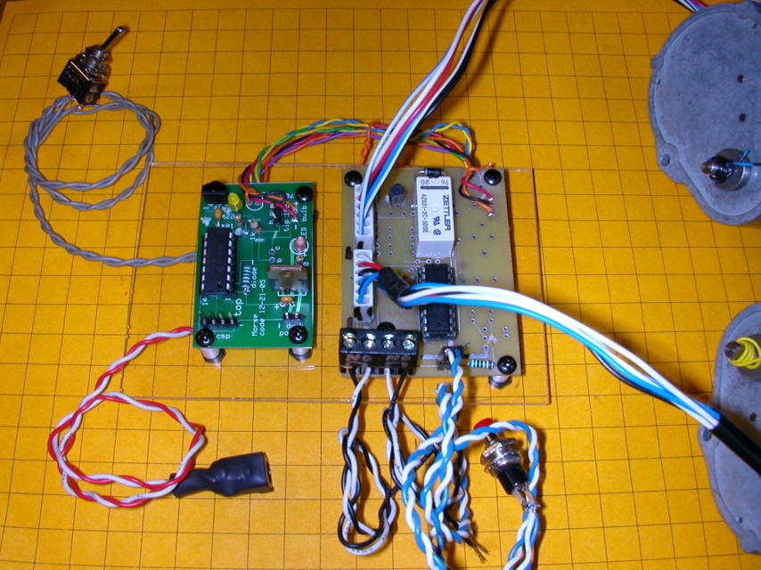
Completed unit:

Here the microcontroller board is shown (top left / green board) along with the auxiliary board (bottom left / brown board) and the two geared Hurst stepper motors.

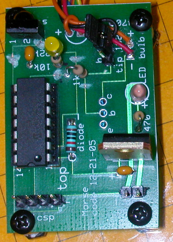
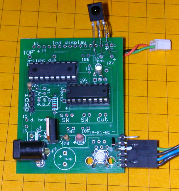
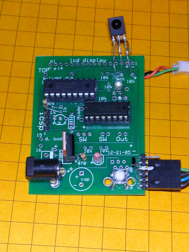
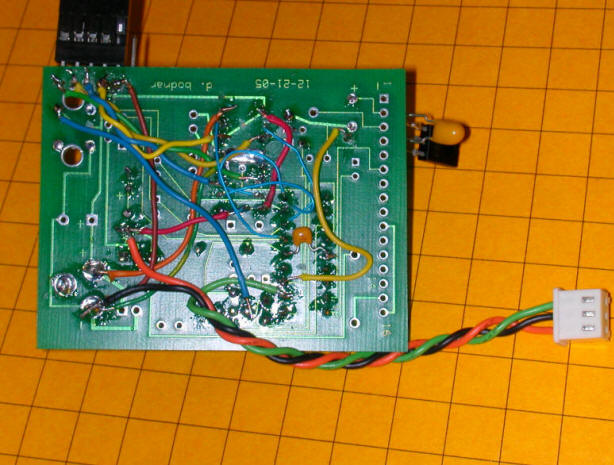
In this view of the microcontroller board the programming jumper is in the upper right area.  Power is applied in the lower right.  The IR sensor is in the upper left next to the yellow LED.

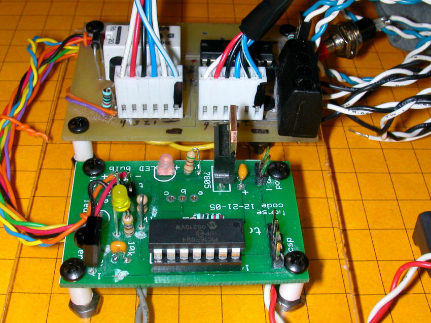
The stepper motors connect to the two six pin headers on the left side of the second board, seen below.  The activation switch (which moves the bridge up or down) connects at the bottom center and the sound unit or other accessory connect via the screw terminals on the bottom left.

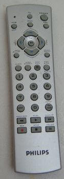
Configuration:

Configuration is done be by way of an infrared TV remote control unit.
When the programming jumper is in place the unit is in program mode and functions can be controlled by the TV remote control unit.  The unit used in this example is a Philips CL015 that is programmed to emulate a Sony remote


Programming:

To test the unit follow this procedure:

1.  Make sure the programming jumper is on the two jumper pins on the green microcontroller board.  This allows the remote control unit to operate the motors
2.  Connect both stepper motors and supply power to the board.  The red power LED should light.
3.  On the remote control press the right arrow (VOL+).  The motors make one rotation (360 steps / 360 degrees) in a clockwise (CW) direction.
4.  Press the left arrow (VOL-) and the motors make one rotation counter clockwise (CCW).
5.  Press the up arrow (CHAN+) and the motors rotate 45 steps (45 degree) CW - note this step rate can be changed.
6.  Press the down arrow (CHAN-) for 45 steps CCW. 

Changing the programmed step number:

1.  To change the number of steps moved by CHAN+ and CHAN- press the END key (lower left)
2.  Type a 4 digit number of degrees, for example 0720 for 2 rotations (720 degrees) - note that the LED flashes out each digit as it is entered - please allow time for each digit to flash out before entering the next digit. 
3.  After the 4th digit has been entered and flashed out the motors will rotate once CW and once CCW the number of degrees entered.
4.  Press either CHAN+ or CHAN- to move the motors the programmed amount.

Fine adjustments:

To move the motor in small increments you can press the following buttons (with the programming jumper installed)

  • Press the 1 Key to move clockwise 1 degree
  • Press the 2 Key to move clockwise 5 degrees
  • Press the 3 key to move clockwise 10 degrees
  • Press the 4 Key to move counterclockwise 1 degree
  • Press the 5 Key to move counterclockwise 5 degrees
  • Press the 6 key to move counterclockwise 10 degrees


Automatic operation:

Once the proper number of steps has been determined and programmed remove the programming jumper.  You can store it by putting in on one of the two pins.

Pressing the UP/DOWN button will move the motors the programmed number of degrees.  The first press of UP/DOWN moves the motors CW. The second press moves the CCW.

Note.  If power is lost while the bridge is up the unit will remember that is was up and the next press will put the bridge down.  If power is lost in the middle of an up or down operation the bridge controller will not know where the bridge was stopped and the unit must be reset by with the remote control unit - (install the programming jumper and use the 1-6 keys (as above) to move the bridge to the bottom or top position before restarting.


As Shipped:

Connect the unit as below for testing.  The grey wires on the left go to the Program / Operate toggle switch.  In the program position the remote control can change setting and align the motors.  In the Operate setting the push button (at the end of the blue/white wires) activates the motors either up or down.  Note that the blue / white wires terminate in a small plug that goes into the board next to the black screw terminal connector.

The red/white wires in the lower left terminate in a power connector that goes to the power supply.  The two pairs of black / white wires are for the NO contacts on the relay.  They connect via the two sets of screw terminals marked NO.

Additional items shipped include

  • Philips universal remote control - programmed to use Sony TV codes
  • Motor cable extension
  • additional connectors to make a second motor cable
  • a second blue / white wire terminating in a header for your up/down switch
  • power supply
  • spare H-bridge chip SN754410NE
  • old controller with a new 7805 voltage regulator

The motors connect as in the photo below.  There is a black mark on one end of each connector that goes next to the black mark on the board.


Software - revision 12-3-06 - most features working:
'12-3-2006 version 1-2
'works properly with Mike Gruber's motors -
'push ENTER to go to program mode - type 4 digit number in degrees
'vol up / vol dn does CW & CCW tests
'
loop var byte
temp0 var byte
temp var word
temp1 var word
temp2 var word
temp3 var byte
LEDTemp1 var byte
LEDTemp2 var byte
LEDTemp3 var byte
TempByte var byte
digit var byte
PauseWord var word
TempWord var word
TempWord2 var word
value var byte
LED var porta.4 'also high 10
ProgramButton var porta.2 'low when hit
relay var portc.5
StartSwitch var porta.5 'pin 2
CW var bit 'CW if 1, CCW if 0
CW_CCW var bit 'stores what was done last
zero con 136
one con 128
two con 129
three con 130
four con 131
five con 132
six con 133
seven con 134
eight con 135
nine con 136
channelUP con 144
channelDOWN con 145
volumeUP con 146
volumeDOWN con 147
OK con 148
Menu con 224
ENTER con 139
x VAR BYTE
steps VAR WORD
stepArray VAR BYTE(4)

stepArray[0] = %00001010
stepArray[1] = %00000110
stepArray[2] = %00000101
stepArray[3] = %00001001
'clear

TRISc = %11100000
IRpulse_length var word(13)
xx var Byte
Command Var Byte
IRin var portc.4 'pin 6
ansel = 0
cmcon0 = 7
trisa.4=0 'make leds output
trisa.5=1
trisc.5=0
trisa.2=1 'start button input
trisc.4=1 'IR input

data @0, 2,208, 0 ' 1,104 = 360 degrees - 3rd digit CW or CCW on start

read 0,temp
read 1, temp1
read 2, CW_CCW
pauseword = temp*256
pauseword=pauseword + temp1
goto Verytop:
again:
high relay:pause 1000:low relay:pause 1000
if programbutton=0 then
for temp=1 to 5
high led:pause 200:low led:pause 200
next temp
endif
if startswitch = 0 then
for temp=1 to 5
high led:pause 100:low led:pause 100
next temp
endif
if programbutton=1 and startswitch=1 then
toggle relay
pause 500
endif
goto again:

VeryTop:
low portc.0:low portc.1:low portc.2:low portc.3


start:
low relay
command=0
gosub GetIR
if Programbutton=0 then
goto Operate:
endif

if command = OK then VeryTop:
if command = ChannelUP then SpinCW:
if command = ChannelDown then SpinCCW:
if command = VolumeUp then Test1:
if command = VolumeDown then test2:
if command = Enter then GetRevSettings:
if command = one then CWone:
if command = two then CWfive:
if command = three then CWten:
if command = four then CCWone:
if command = five then CCWfive:
if command = six then CCWten:

goto start:

CWone:
CW=1
gosub step1
pause 100
goto verytop

CWfive:
CW=1
for temp3=1 to 5
gosub step1:
next temp3
pause 100
goto verytop

CWten:
CW=1
for temp3=1 to 10
gosub step1:
next temp3
pause 100
goto verytop

CCWone:
CW=0
gosub step1
pause 100
goto verytop

CCWfive:
CW=0
for temp3=1 to 5
gosub step1:
next temp3
pause 100
goto verytop

CCWten:
CW=0
for temp3=1 to 10
gosub step1:
next temp3
pause 100
goto verytop

SpinCW:
cw=1
for tempword=1 to pauseword
gosub step1:
next Tempword
goto verytop:


SpinCCW:
cw=0
for tempword=1 to pauseword
gosub step1:
next Tempword
goto verytop:

Test1:
cw=1
tempword2=360
for tempword=1 to tempword2
gosub step1:
next tempword
goto verytop:

Test2:
cw=2
tempword2=360
for tempword=1 to tempword2
toggle LED
gosub step1:
next tempword
goto verytop

Operate:
if programbutton=1 then start:
low relay
if startswitch = 0 then Operate:
if CW_CCW=1 then
cw=1
else
cw=0
endif
cw_ccw = not(cw_ccw)
write 2,CW_CCW
high relay :high led ':pause 1000:low relay:low led:pause 1000:high relay:high led:pause 500
for tempword=1 to pauseword
gosub step1
next tempword
low relay :low led
WaitForRelease:
if startswitch=1 then WaitForRelease:
goto verytop

Test3:
cw=1
tempword2=360
for tempword=1 to tempword2
gosub step1:
next tempword
low portc.0:low portc.1:low portc.2:low portc.3
pause 2000
cw=2
tempword2=360
for tempword=1 to tempword2
toggle LED
gosub step1:
next tempword
low portc.0:low portc.1:low portc.2:low portc.3
goto verytop

Test4:
cw=1
tempword2=pauseword
for tempword=1 to tempword2

gosub step1:
next tempword

pause 2000

cw=2
tempword2=pauseword
for tempword=1 to tempword2
toggle LED
gosub step1:
next tempword
return

GetIR:
Getstartbits:
Pulsin IRin ,0,IRpulse_length(0)
if IRpulse_length(0) < 200 then
return
Endif

for xx=1 to 12
pulsin IRin,0,IRpulse_length(xx)
next xx

displaybits:
if IRpulse_length(1) < 100 then
Command.bit0 = 0
Else
Command.bit0 = 1
endif
if IRpulse_length(2) < 100 then
Command.bit1 = 0
Else
Command.bit1 = 1
endif
if IRpulse_length(3) < 100 then
Command.bit2 = 0
Else
Command.bit2 = 1
endif
if IRpulse_length(4) < 100 then
Command.bit3 = 0
Else
Command.bit3 = 1
endif
if IRpulse_length(5) < 100 then
Command.bit4 = 0
Else
Command.bit4 = 1
endif
if IRpulse_length(6) < 100 then
Command.bit5 = 0
Else
Command.bit5 = 1
endif
if IRpulse_length(7) < 100 then
Command.bit6 = 0
Else
Command.bit6 = 1
endif
if IRpulse_length(8) < 100 then
Command.bit7 = 0
Else
Command.bit7 = 1
Endif
If Command.bit7 = 0 then 'Bit 7 is one of the device bits
Command = Command + 1
Endif
If Command = 10 then
Command = 0
Endif
return


Step1:
for temp0=1 to 4
if CW = 1 then
steps = steps + 1
else
steps = steps - 1
endif
portc = stepArray[steps //4]
high relay
pause 3 '2 seems to be a minimum
next temp0
return

GetRevSettings:
digit=4
PauseWord=0

high LED:pause 1000:low LED
GetRevSettings0:
gosub getir
if command=0 then GetRevSettings0
if command > 137 or command < 128 and command <>139 and command <> 0 then
goto VeryTop: 'abort on non number 0-9
endif
if command=139 then GetRevSettings0
Value=command-127

if Value = 10 then value=0

if value=0 then high LED:pause 500:low LED
for tempbyte=1 to value:High LED:pause 200:low LED:pause 200:next tempbyte
PauseWord=PauseWord*10+Value
digit=digit-1

pause 200:command=0
if digit=0 then
temp0= pauseword / 256
write 0, temp0
temp1 = temp0*256
temp2= pauseword-temp1
write 1, temp2
'gosub test4:
goto VeryTop:
endif
goto GetRevSettings0


16F88 Version

This modification to the circuit above utilizes a 16F88 PIC processor and the circuit board that was originally designed for the train speedometer.

Software  IR_StepperMotorControl_16f88_V2-0

'12-22-2006 version 1-3 - WORKS
'need to use serout2 to match oscillator speed between serout and ir read
'on green speedo board with H-bridge
'works properly with 6 wire stepper (old hard drive?)
'push ENTER to go to program mode - type 4 digit number in degrees
'vol up / vol dn does CW & CCW tests
'
Include "modedefs.bas"

cmcon=7 'allows you to use pins as digital rather than analog
ansel=0 'allows you to use pins as digital rather than analog
@ DEVICE PIC16F88, INTRC_OSC_NOCLKOUT, WDT_OFF, LVP_OFF, PWRT_ON, PROTECT_ON, BOD_ON
dEFINE OSC 8
OSCCON = %01100111 'MUST BE USED to set clock speed =$67 = 4mhz
'osccon = $70 ' 01110000 = 8 mhz

p_len var byte

loop var byte
temp0 var byte
temp var word
temp1 var word
temp2 var word
temp3 var byte
temp4 var word
LEDTemp1 var byte
LEDTemp2 var byte
LEDTemp3 var byte
TempByte var byte
digit var byte
PauseWord var word
TempWord var word
TempWord2 var word
value var byte
LED var porta.2 'also high 10
'ProgramButton var porta.2 'low when hit
relay var portb.5
StartSwitch var porta.5 'pin 2
CW var bit 'CW if 1, CCW if 0
CW_CCW var bit 'stores what was done last
zero con 136
one con 128
two con 129
three con 130
four con 131
five con 132
six con 133
seven con 134
eight con 135
nine con 136
channelUP con 144
channelDOWN con 145
volumeUP con 146
volumeDOWN con 147
OK con 148
Menu con 224
ENTER con 139
x VAR BYTE
steps VAR WORD
stepArray VAR BYTE(4)
serial_out var porta.3
vwhole var byte
vdecimal var byte
vwhole=2
vdecimal=0
stepArray[0] = %00001010
stepArray[1] = %00000110
stepArray[2] = %00000101
stepArray[3] = %00001001
'clear

TRISb = %11110000
IRpulse_length var word(13)
xx var Byte
Command Var Byte
IRin var porta.4 'pin 15
'ansel = 0
'cmcon0 = 7
trisa.4=0 'make leds output
trisa.5=1
trisb.5=0
trisa.2=1 'start button input
trisa.4=1 'IR input
trisa.3=0
data @0, 0,48, 0 ' 1,104 = 360 degrees - 3rd digit CW or CCW on start
'again2:low led:pause 500: high led:pause 500:low led:pause 500:goto again2:
read 0,temp
read 1, temp1
read 2, CW_CCW
pauseword = temp*256
pauseword=pauseword + temp1
temp4=0
pause 300
serout2 serial_out, 188,["?f?c0"]:pause 300:
serout2 serial_out, 188,["?f?c0"]:pause 200 '?c0 turns cursor off
serout2 serial_out, 188,["?B40"]:pause 200 'set brightness of LCD
serout2 serial_out, 188,["Stepper Motor Test?nd. bodnar 12-2006?nVersion ",#vwhole,".",#Vdecimal]
pause 200


'serout serial_out, t2400,["?y3?x00Row 0:Column 0 ",#temp2]
'end


goto Verytop:
again:
high relay:pause 1000:low relay:pause 1000
'if programbutton=0 then
for temp=1 to 5
high led:pause 200:low led:pause 200
next temp
'endif
if startswitch = 0 then
for temp=1 to 5
high led:pause 100:low led:pause 100
next temp
endif
'if programbutton=1 and startswitch=1 then
toggle relay
pause 500
'endif
goto again:

VeryTop:
low portb.0:low portb.1:low portb.2:low portb.3


start:
low relay
command=0
'goto test2:goto start:
gosub GetIR
'if Programbutton=0 then
' goto Operate:
'endif

if command = OK then VeryTop:
if command = ChannelUP then SpinCW:
if command = ChannelDown then SpinCCW:
if command = VolumeUp then Test1:
if command = VolumeDown then test2:
if command = Enter then GetRevSettings:
if command = one then CWone:
if command = two then CWfive:
if command = three then CWten:
if command = four then CCWone:
if command = five then CCWfive:
if command = six then CCWten:

goto start:

CWone:
CW=1
gosub step1
pause 100
goto verytop

CWfive:
CW=1
for temp3=1 to 5
gosub step1:
next temp3
pause 100
goto verytop

CWten:
CW=1
for temp3=1 to 10
gosub step1:
next temp3
pause 100
goto verytop

CCWone:
CW=0
gosub step1
pause 100
goto verytop

CCWfive:
CW=0
for temp3=1 to 5
gosub step1:
next temp3
pause 100
goto verytop

CCWten:
CW=0
for temp3=1 to 10
gosub step1:
next temp3
pause 100
goto verytop

SpinCW:
cw=1
for tempword=1 to pauseword
gosub step1:
next Tempword
goto verytop:


SpinCCW:
cw=0
for tempword=1 to pauseword
gosub step1:
next Tempword
goto verytop:

Test1:
cw=1
tempword2=36
for tempword=1 to tempword2
gosub step1:
next tempword
goto verytop:

Test2:
cw=2
tempword2=36
for tempword=1 to tempword2
'toggle LED
gosub step1:
next tempword
goto verytop

Operate:
'if programbutton=1 then start:
low relay
if startswitch = 0 then Operate:
if CW_CCW=1 then
cw=1
else
cw=0
endif
cw_ccw = not(cw_ccw)
write 2,CW_CCW
high relay :high led ':pause 1000:low relay:low led:pause 1000:high relay:high led:pause 500
for tempword=1 to pauseword
gosub step1
next tempword
low relay :low led
WaitForRelease:
if startswitch=1 then WaitForRelease:
goto verytop

Test3:
cw=1
tempword2=360
for tempword=1 to tempword2
gosub step1:
next tempword
low portb.0:low portb.1:low portb.2:low portb.3
pause 2000
cw=2
tempword2=360
for tempword=1 to tempword2
'toggle LED
gosub step1:
next tempword
low portb.0:low portb.1:low portb.2:low portb.3
goto verytop

Test4:
cw=1
tempword2=pauseword
for tempword=1 to tempword2

gosub step1:
next tempword

pause 2000

cw=2
tempword2=pauseword
for tempword=1 to tempword2
'toggle LED
gosub step1:
next tempword
return

GetIR:
low led
p_len=100
'temp4=temp4+1
'Serout serial_out, t2400,["?y2?x00At GetIR ",#temp4," "]
Getstartbits:
Pulsin IRin ,0,IRpulse_length(0)
if IRpulse_length(0) < 200 then 'was 200 for 4 mhz clock
return
Endif
'toggle led
'Serout serial_out, t2400,["?y2?x00At GetIR PAST < 200 "]
for xx=1 to 12
pulsin IRin,0,IRpulse_length(xx)
next xx

displaybits:
if IRpulse_length(1) < p_len then 'was 100 for 4 mhz clock
Command.bit0 = 0
Else
Command.bit0 = 1
endif
if IRpulse_length(2) < p_len then
Command.bit1 = 0
Else
Command.bit1 = 1
endif
if IRpulse_length(3) < p_len then
Command.bit2 = 0
Else
Command.bit2 = 1
endif
if IRpulse_length(4) < p_len then
Command.bit3 = 0
Else
Command.bit3 = 1
endif
if IRpulse_length(5) < p_len then
Command.bit4 = 0
Else
Command.bit4 = 1
endif
if IRpulse_length(6) < p_len then
Command.bit5 = 0
Else
Command.bit5 = 1
endif
if IRpulse_length(7) < p_len then
Command.bit6 = 0
Else
Command.bit6 = 1
endif
if IRpulse_length(8) < p_len then
Command.bit7 = 0
Else
Command.bit7 = 1
Endif
If Command.bit7 = 0 then 'Bit 7 is one of the device bits
Command = Command + 1
Endif
If Command = 10 then
Command = 0
Endif
'if command=128 then toggle led
serout2 serial_out, 188,["?y3?x00Command= ",#command]
return


Step1:
for temp0=1 to 4
if CW = 1 then
steps = steps + 1
else
steps = steps - 1
endif
portb = stepArray[steps //4]
high relay
' pause 1 '2 seems to be a minimum
high led:pause 1:low led
next temp0
return

GetRevSettings:
digit=4
PauseWord=0

high LED:pause 500:low LED
GetRevSettings0:
gosub getir
if command=0 then GetRevSettings0
if command > 137 or command < 128 and command <>139 and command <> 0 then
goto VeryTop: 'abort on non number 0-9
endif
if command=139 then GetRevSettings0
Value=command-127

if Value = 10 then value=0

if value=0 then high LED:pause 250:low LED
for tempbyte=1 to value:High LED:pause 100:low LED:pause 100:next tempbyte
PauseWord=PauseWord*10+Value
digit=digit-1

pause 100:command=0
if digit=0 then
temp0= pauseword / 256
write 0, temp0
temp1 = temp0*256
temp2= pauseword-temp1
write 1, temp2
'gosub test4:
goto VeryTop:
endif
goto GetRevSettings0