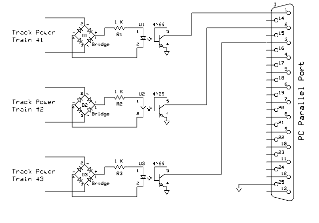
| Computer connection: An old computer running Windows 98 is used to sense when power is being supplied to the tracks. The interface below connects to the PC's parallel port. Windows 98 is used as Windows 2000, XP and Vista do not allow Quick Basic to directly access the pins on the computer's parallel port.
Bridge rectifiers D1, D2 and D3 connect directly to the power feeds to each track. They allow the circuit to work properly regardless of the polarity of the DC track power. The output from each bridge rectifier goes to an optoisolator through a 1,000 ohm current limiting resistor. The collector output (pin 5) from the optoisolator goes directly to pins 2, 3 or 4 on the PC's parallel port. Pin 25 from the PC port must share a ground with the optoisolators. |
| Data collection: Every minute the software checks the status of the power on each of the three tracks. Every 10 minutes this data is complied, graphed and sent to an on-line web page. |
| Data collection software: |
| Graph creation with GNU Plot: |
| FTP upload to web page: |