|
Introduction Getting video from one camera on the front porch to a TV in the basement is a trivial undertaking but, as projects like this are apt to do, this undertaking has grown into a multi-camera system that can be viewed in the workshop or from any computer that is connected to the Internet. There are many commercial systems that can do all that this project does and more but few can match the price and none can let you say that you put it all together yourself! A four color camera system can be assembled for less than $200 and connected to a Windows computer that you probably already have. Commercial units that do the same thing can cost $300, $400 or more with the least expensive units only offering black & white cameras. There are six sub-systems that are used in this project:
The web cam system is currently
running on my home network and can be viewed from your browser at
this URL: One camera is mounted on my front porch and aimed at the front door and mailbox so that I can easily check for visitors, mail and other deliveries. The second camera looks down on the driveway so that I can see when someone arrives by car. There are two other cameras connected to the system that may or may not be active at any given time. One looks over the pond, garden and garden railroad and the other gives a view of the front yard. If you visit the site you will note that there is a link to some control options. You are welcome to experiment with them but they are not part of this article. If interest dictates the control system can be the topic of another article. |
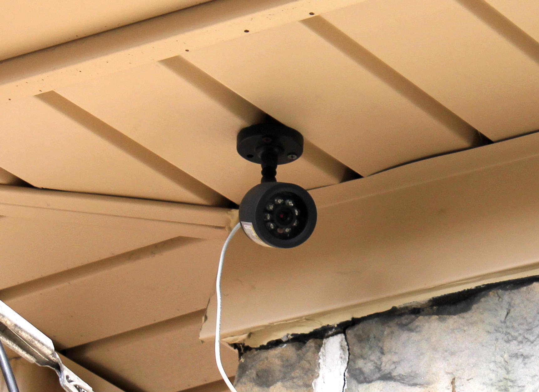
| Cameras The cameras that I used are from Harbor Freight, Part # 95914. These cameras are frequently on sale and can be purchased for around $30. The camera enclosures have proven to be weather proof when protected from direct rainfall and can easily be mounted under the eves of the roof. <images/CameraUnderEaves.jpg>
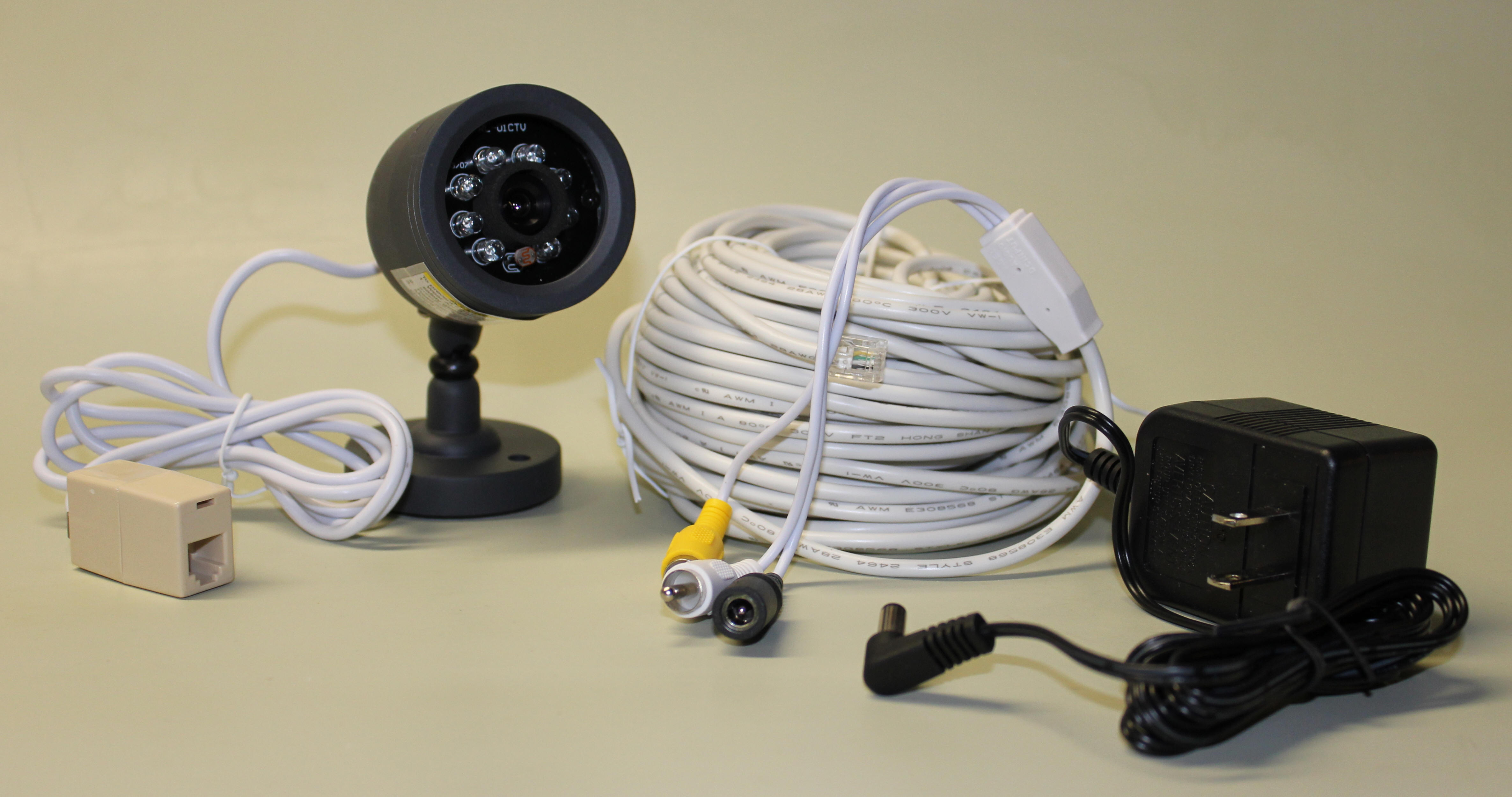
The 80 foot cable that is included with the camera makes it easy to get the video signal to my computer from just about anywhere in the house. Any camera, black & white or color, should work for this project so long as it has a composite video output Composite video can usually be identified by checking the cable end as most use male RCA connectors like the white and yellow ones in the photo. <images/HF_inBox-18.jpg>
The Harbor Freight cable connects to the camera through a six conductor RJ11 telephone plug. The other end of the cable terminates in two RCA connectors and one power connector. The yellow plug is the composite video from the camera. The white plug is audio from a microphone in the camera head. Power comes from a small wall wart that plugs into the black connector at the end of the cable. Although the software that I use is not set up to provide audio I do use one of the camera's microphones to listen for the sound of the newspaper hitting the driveway when I am working in my office early in the morning. I just connect the audio plug from one of the cameras to an old pair of computer speakers and it works very well. Make sure that you protect the RJ11 connector that is used to join the short camera cable to the 80 foot cable. The only problem I have had to date stemmed from this connector getting wet and corroding. I just cleaned the connection and put the connector inside of a sealed up plastic bag and have had no problems since. |
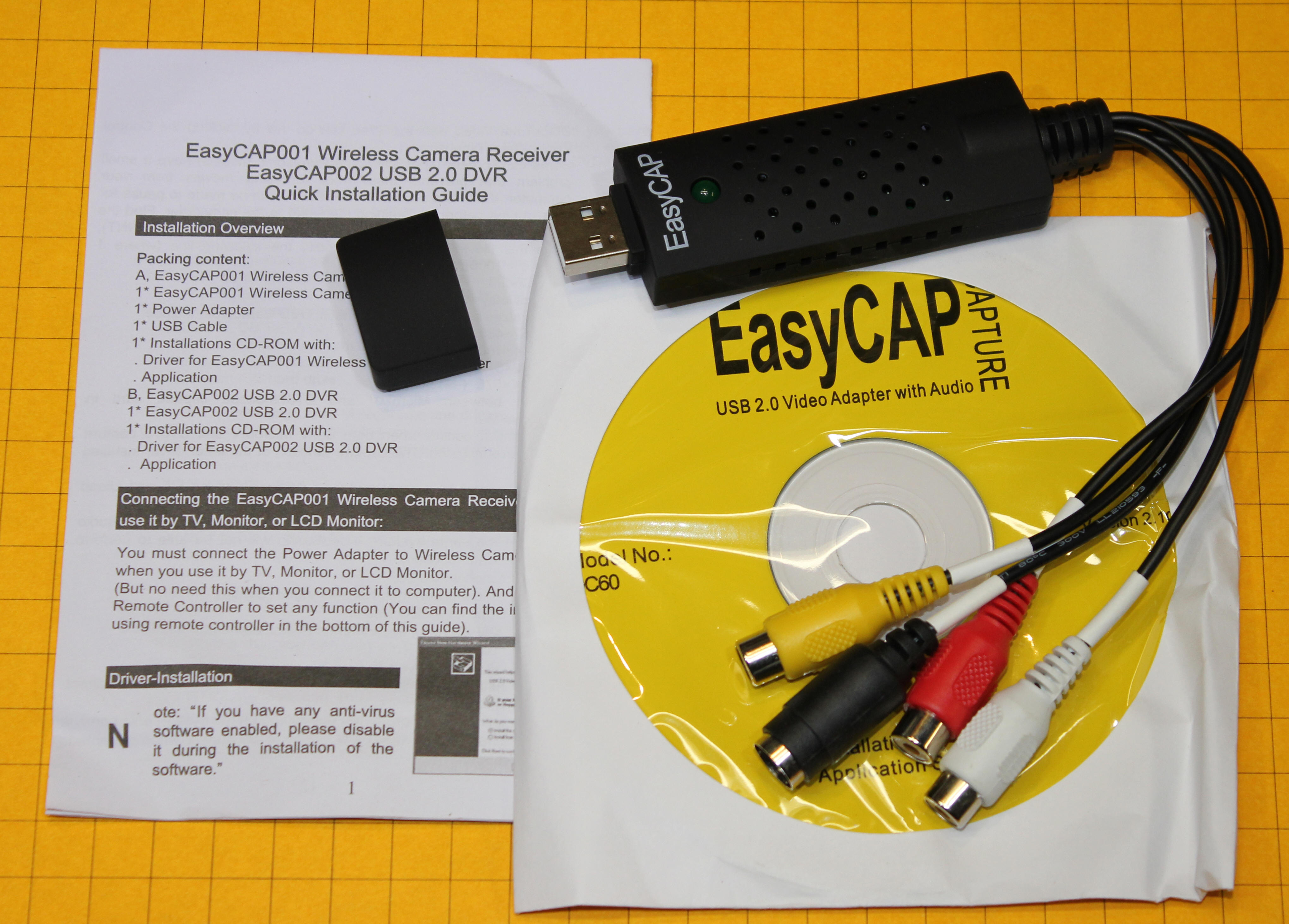
| Composite Video to USB Adapter The composite video output from the camera needs to get into the computer in order to stream it onto the Internet. My first experiments were with an expensive (more than $100) Pinnacle TV tuner / video adapter. It worked well but I didn't want to dedicate such an expensive (and overly capable) unit to this project. Some research on eBay brought me to the EasyCAP Video Adapter which I purchased for less than $10, including shipping! They are also available from Amazon. <images/EasyCap-12.jpg>
Just search eBay or Amazon for "EASYCAP" to find the unit. Driver software is included and it installed easily. More importantly the device has worked flawlessly for more than a year. One word of caution. The units I have gotten are set for PAL video. Make sure you set them to NTSC if you are using the unit in the US. |
| PC with USB2 Any Windows based PC with USB2 can be used to stream the video. An older computer without USB2 can be used but the streaming software will automatically limit the size of the image. If you must use an older computer you may want to install an add-on USB2 adapter. Although the system will work and give satisfactory results while using an older, slower computer a faster more contemporary system is recommended, especially when setting it up for the first time. |
| Web Streaming Software There are a number of programs that will stream video onto the web. I chose to use YawCam ( http://yawcam.com ) for a number of reasons.
In addition YawCam has a number of features that I don't use but that may be important to you. These include the capability to send an email when activity is detected by a camera and setting up a schedule for when the video will be available on-line. |
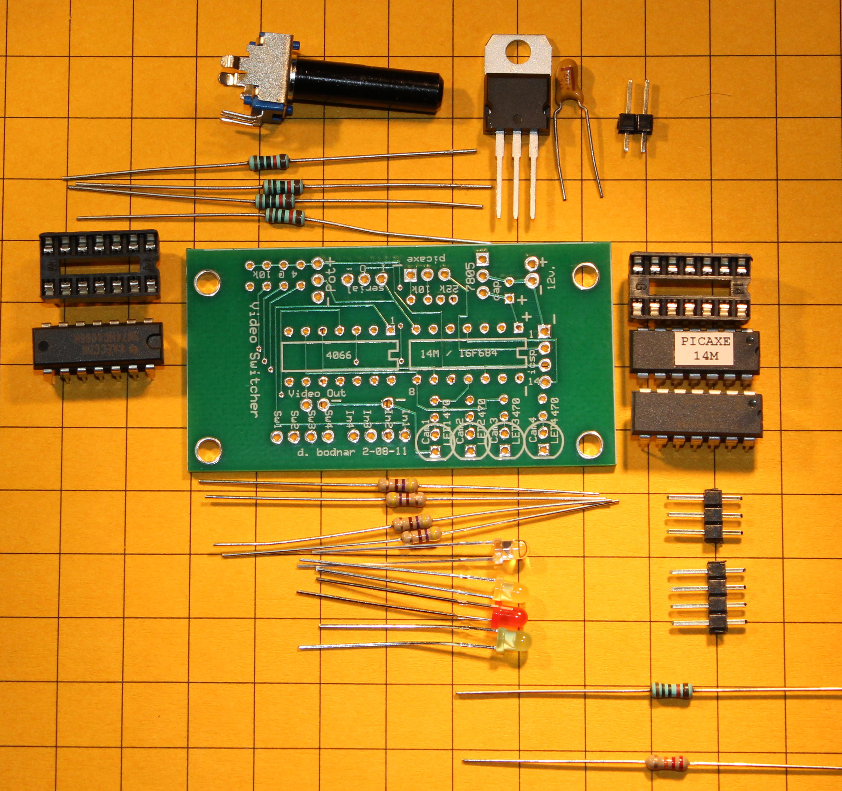
| Video Switcher The idea of being able to use two or more cameras appealed to me so a video switcher was needed. If you do not plan on using more than one camera you can skip this step. The video switcher is NOT a complex device and is made up of only two integrated circuits. A 4066, a quad analog switch, takes care of switching the video inputs. A PICAXE 14M or a PIC 16F684 processor controls which cameras are active and the time the video from each camera is shown. Four toggle switches allow you to choose the video inputs that will be displayed and a potentiometer is used to select scan speed. When I first started doing research to design a video switcher I thought that I would find that it would be much more involved that it turned out to be. The 4066 makes it very easy to switch between cameras. The only down side to using this chip is an occasional bit of interference that can be observed when switching between cameras. This may not be the fault of the 4066 but of the Video to USB adapter as it adjusts to a new camera image. The schematic for the PICAXE 14M control system is shown here. The 4066 is at the right. All four of the switch sections are being used. The video from camera 1 (the center lead from the RCA connector) goes to pin 1, camera 2 goes to pin 11, camera 3 to pin 8 and camera 4 to pin 4. All of the connections from the cameras' shields are tied together and connected to ground . The four output pins on the 4066 (pins 2, 3, 9 and 10) are tied together and go to the input of the USB video adapter. The PICAXE selects between the inputs and shows each video stream for a time period that can be adjusted by the potentiometer, R11. <images/Schematic_14m.gif>
The four SPST toggle switches (labeled Camera 1 through Camera 4) determine which cameras are included in the scan. The potentiometer that is connected to pin 7 of the PICAXE is used to adjust the scanning rate which can be varied from 1 second to about 30 seconds. Even though the potentiometer in the schematic is labeled as 50k any linear pot from 10k to 100k could be used. The schematic for the 16F684 is shown here and is almost identical to the one for the 14M. They should be similar as the PICAXE 14M is a PIC 16F684 with the PICAXE software loaded onto it! The main differences are the programming connection through ICSP (In Circuit Serial Programming) and the serial out pin that can be used to view the debug output from the program on a terminal. <images/Schematic16F684.gif>
|
| Software The software versions for the PICAXE and the PIC Basic Pro based 16F684 are nearly identical. The main differences are in how variables and pins are named. The software only needs to do three things:
PICAXE Software |
| PIC Software The program listing for the PIC 16F684 is very similar to the software for the PICAXE. It is written in PICBasic Pro. Please take note of the two cautionary comments at the top. You must configure your programmer so that pin 4 (MCLR) is set to be an input pin and you must have the switch connected to that pin (UseCamera3) set to off in order to program using ICSP. '01-13-2012 - Web Cam Video Switcher - revised reversing switch numbers ' NOTE- must set MCLR_OFF pin to input in programmer, not here! ' CANNOT PROGRAM using ICSP with Switch for UseCamera3 ON ! ! ! DEFINE DEBUG_REG PORTA DEFINE DEBUG_BIT 0 'a.0 is PIN 13 on 16f684 DEFINE DEBUG_BAUD 9600 DEFINE DEBUG_MODE 1 'DEBUG mode: 0 = true, 1 = inverted ansel=0 'use pins as digital rather than analog CMCON0= 7 'Disable comparator - makes portc LEDs work properly DEFINE OSC 8 'use 8 mhz oscillator OSCCON = $70 'set clock speed INTCON = %00001100 '00xx11xx to be CCP1 mode SerialOut var porta.0 'pin 13 NotUsed12 var porta.1 'pin 12 Camera1 var porta.2 'pin 11 Camera2 var portc.0 'pin 10 Camera3 var portc.2 'pin 8 Camera4 var portc.1 'pin 9 NotUsed2 var porta.5 'pin 2 DelayPOT var portc.3 'pin 7 UseCamera4 VAR porta.4 'pin 3 UseCamera3 VAR porta.3 'pin 4 UseCamera2 VAR portc.5 'pin 5 UseCamera1 VAR portc.4 'pin 6 temp var byte temp2 var word PotReading var byte Delay VAR word Test VAR byte CommandIN VAR byte 'data from web page Loopie VAR word Loopie2 var word Cam1On VAR Bit '=0 if off, =1 if on Cam2On VAR Bit Cam3On VAR Bit Cam4On VAR Bit TimeFudge con 10 trisa = %00011000 trisc = %11111000 'testtop: DEBUG 10,13,10,13,10,13,"Video Switcher - LEDs, Four Switches & Pot for WebCam",10,13 DEBUG "(c) d. bodnar v 1.4 01-13-12",10,13 Start: adcin 7,PotReading Delay = potreading *100 'adjust up or down to change scan range Delay = Delay + 1000 ' one second minimum DEBUG "Delay Time = ",#delay,10,13 IF UseCamera1=0 THEN debug "one active",10,13 LOW Camera2:LOW Camera3:LOW Camera4 HIGH Camera1 PAUSE Delay ENDIF IF UseCamera2=0 THEN debug "two active",10,13 LOW Camera1:LOW Camera3:LOW Camera4 HIGH Camera2 PAUSE Delay ENDIF IF UseCamera3=0 THEN debug "three active",10,13 LOW Camera1:LOW Camera2:LOW Camera4 HIGH Camera3 PAUSE Delay ENDIF IF UseCamera4=0 THEN debug "four active",10,13 LOW Camera1:LOW Camera2:LOW Camera3 HIGH Camera4 PAUSE Delay ENDIF IF UseCamera1=1 AND UseCamera2=1 AND UseCamera3=1 AND UseCamera4=1 THEN debug "NONE active",10,13 LOW Camera1:LOW Camera2:LOW Camera3:LOW Camera4 ENDIF GOTO Start: |
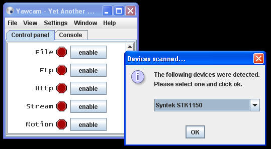
| Setting up YawCam Plug the EASYCAP into into the computer's USB port. You will be prompted to install a driver. Select Install Driver From a Specific Location and browse to the CD drive that contains the EASYCAP CD. Select the Drivers directory on the CD and proceed with the driver installation. If you are told that the driver has not passed "Windows Logo Testing" just select "Continue Anyway" to install the STK1150 driver. Download YawCam from their web site at http://yawcam.com/download.php and install it on your computer. Once installed run YawCam and select Settings from the menu then Detect WebCam. You should see the Syntek STK1150 in the list of devices. <images/YawCam1.jpg>
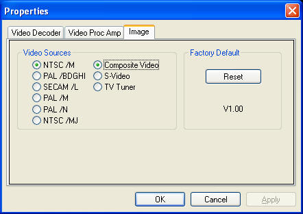
Next select Settings again then Device (Syntek STK1150) then Device Properties. Select the Image tab and, if you are in the US, change the Video Standard from PAL to NTSC_M. Select Composite Video from the same screen and click OK. <images/YawCam2.jpg>
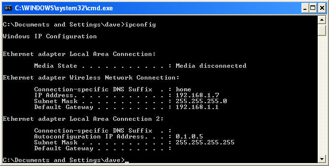
Return to the main menu and select Settings, Edit Settings. Click on Startup, on the left, and select "Start Stream Output". Click OK when done. Click on Stream, on the left, and take note of the default port number, which should be 8081. I changed this to 8888 to accommodate some other devices on my network but you should be able to leave it at 8081. There are a number of other options that can be changed but those are the ones that you need to deal with to get the program working. Return to the main menu and select File / Enable Stream-output. Your computer's firewall may warn you that it is blocking a port. If this happens select Unblock and your streaming image should be active. To see the webcam image you need to find your local IP address. The easiest way to do this is to go to a command prompt by clicking on the Windows Button (lower left of the computer screen) and selecting Run. When the Run box appears type in CMD and press Enter. You should see a black DOS box. In that box type ipconfig and press ENTER. If you are using Windows 7 just type CMD into the Search programs and files box that appears when you click the Windows Button. <images/YawCam3.jpg>
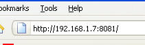
This screen shot is from Windows XP but other versions of Windows will show something similar. Look for IP Address on the screen. Mine is 192.168.1.7. Yours should be similar. If you are using Windows 7 do not use the IPv6 address. Use the IPv4 address. Start your browser and type your IP address followed by :8081 into the address area at the top of your browser. Here is what that looks like in Firefox <images/YawCam4.jpg>
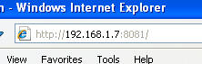
and in Internet Explorer. <images/YawCam5.jpg>
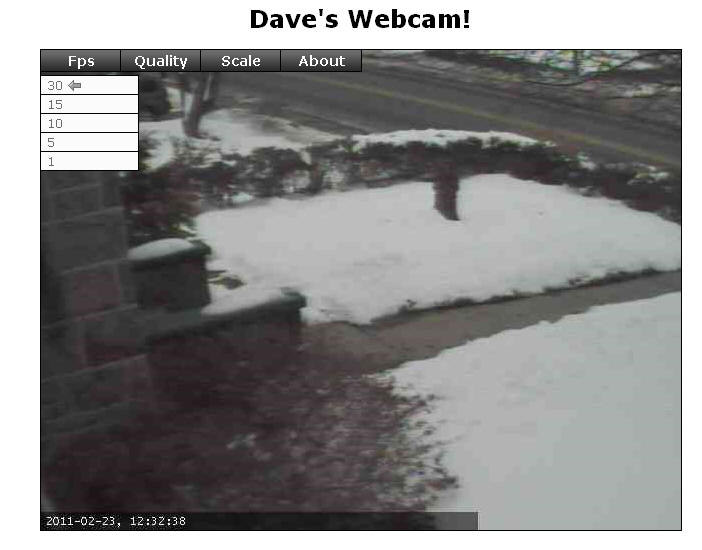
You should see the YawCam web server screen with your web cam image displayed in it. <images/YawCam6.jpg>
|
| Router Configuration In order to get the steaming video onto the Internet you must configure your router and/or firewall to permit the web serving computer to be seen. This usually involves setting Port Forwarding so that the computer's IP address can be accessed from outside the firewall. The web site http://portforward.com/ gives detailed information on how to configure a great number of different routers. It is likely that yours will be found in the list. You must also check your local IP address from time-to-time as most Internet Service Providers change your IP address at seemingly random intervals. I use a free service from www.noip.com called No-IP™ Free Dynamic DNS which automatically checks the local IP address and gives you a link to use for the latest IP. A small program is installed on your home PC to update your IP address. That is the reason that the web address for my web cam is http://n3enm.hopto.org:8888/ . I chose the prefix "n3enm", my ham radio call, at one of their domanis, "hopto.org". 8888 is the port number that I chose for output from YawCam. Note that there is a colon (:) between ".org" and "8888".
If you are only going to view the streaming video from YawCam from within your home there is no need to modify the router or use the services of DynDNS. All you need to do is determine the IP address of the computer that is running YawCam + ":8081". On my system I go to http://192.168.1.214:8888/ as that is the local address for the YawCam web server followed by the port I am using, 8888. If your router dynamically assigns IP addresses (most do) you will need to assign a static IP address for the computer running YawCam. The folks at PortForward.com have instructions for that process, too. See: http://portforward.com/networking/static-xp.htm |
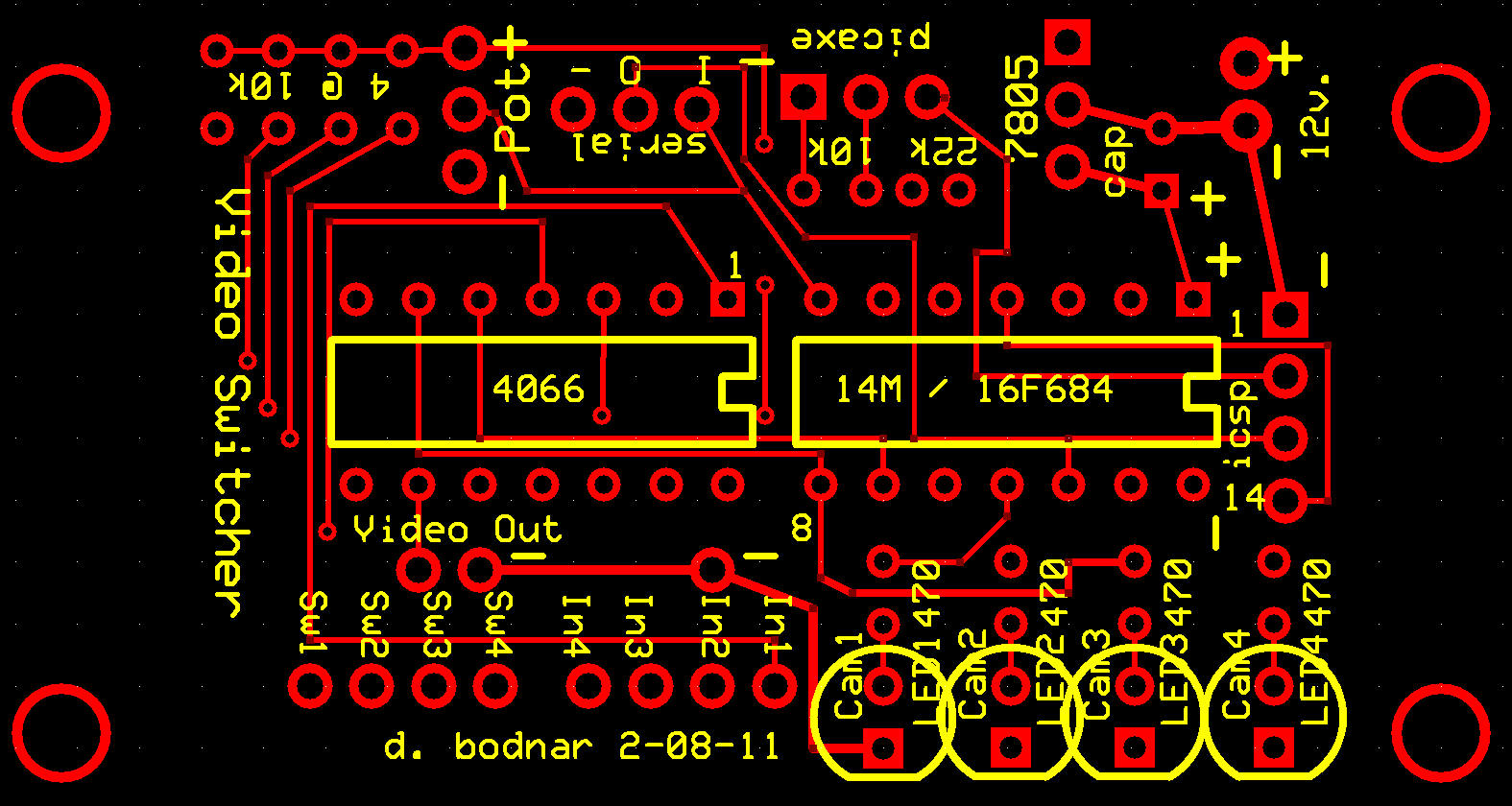
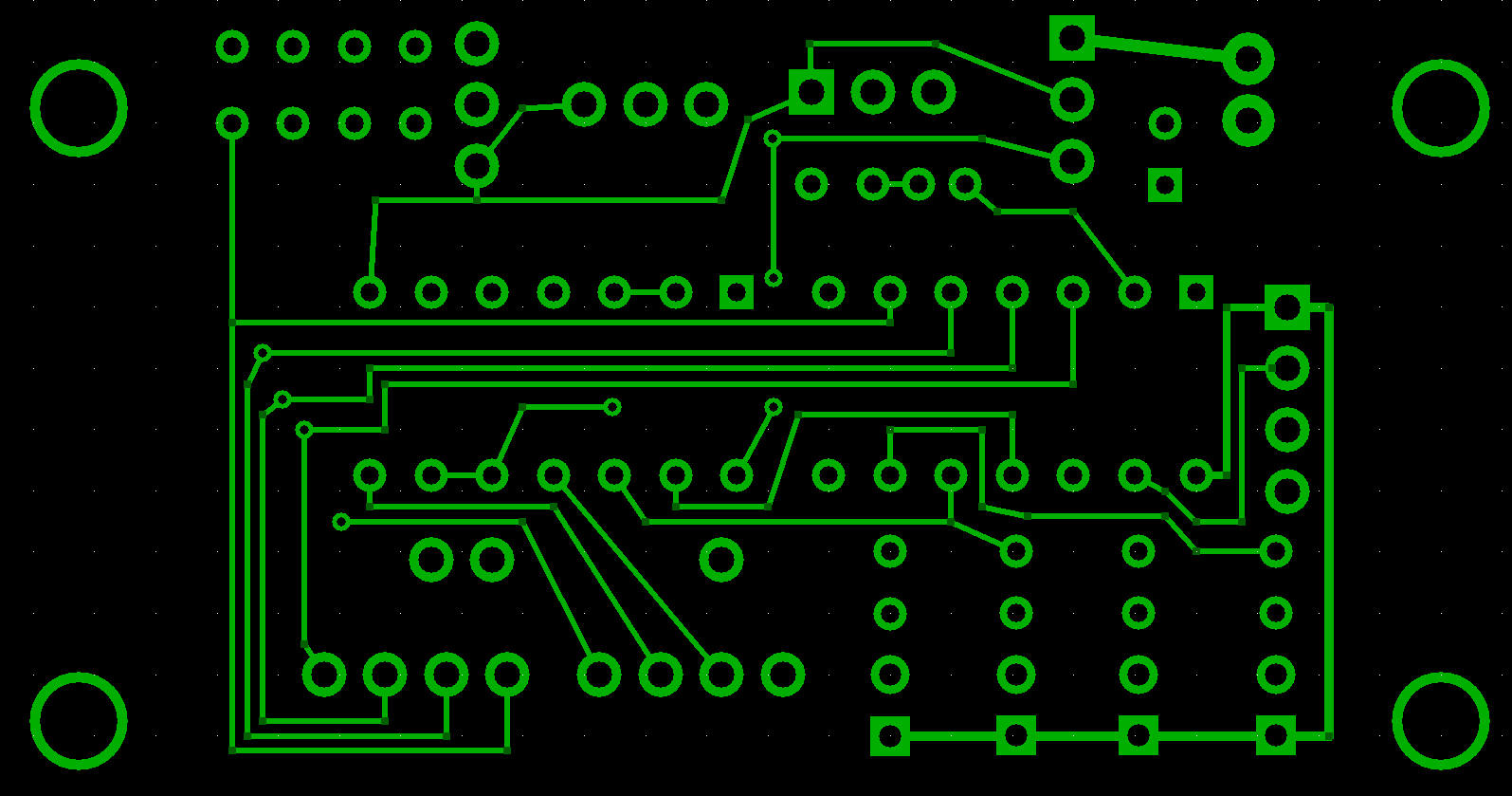
| The Prototype & a Custom Circuit Board The prototype for the circuit was built on a project board. After it was proven to be a successful circuit I designed a custom circuit board using Express PCB's software. The circuit can accommodate either the PICAXE 14M or a PIC 16F684. TOP of circuit board: <images/BoardTop.jpg>
BOTTOM of circuit board: <images/BoardBottom.jpg>
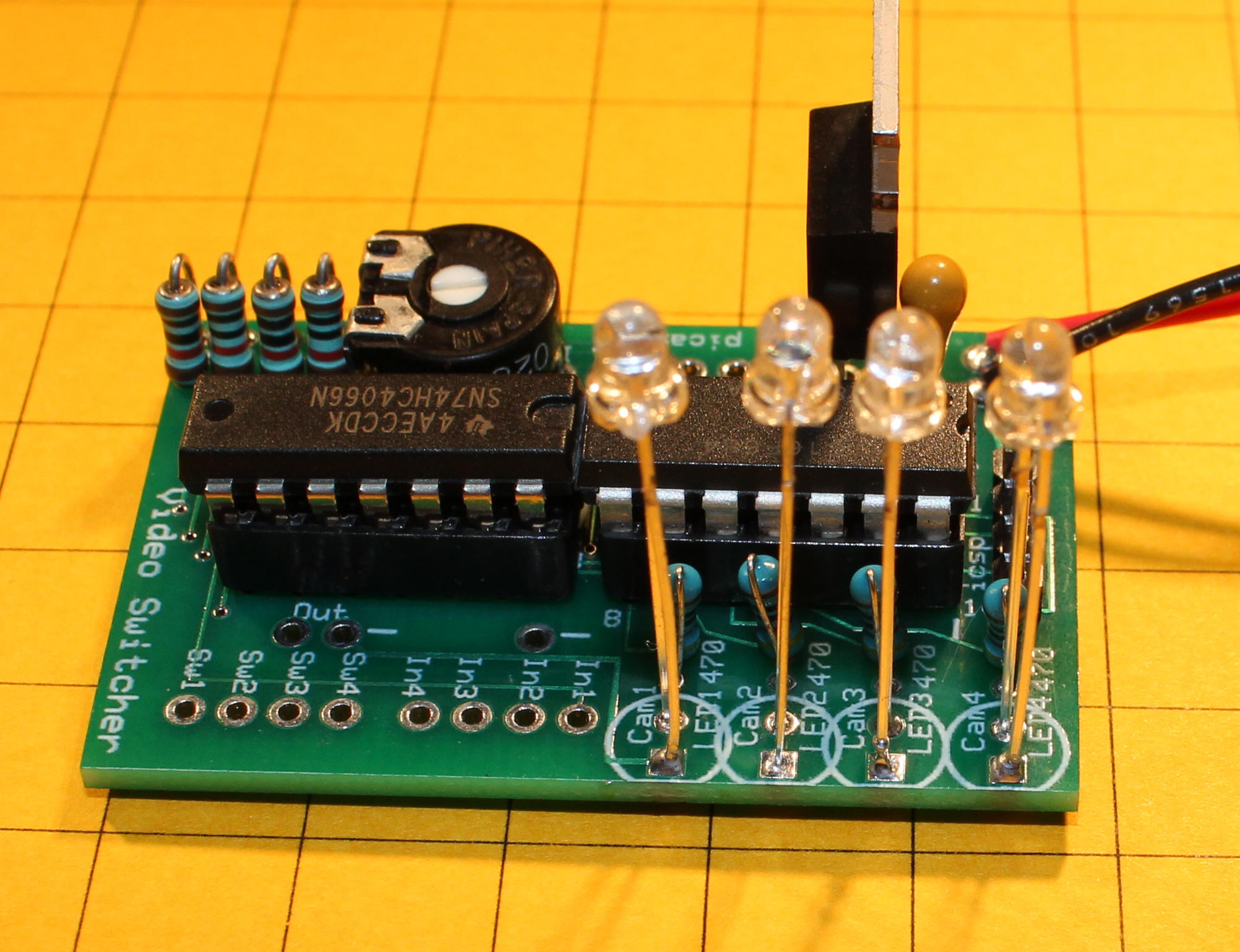
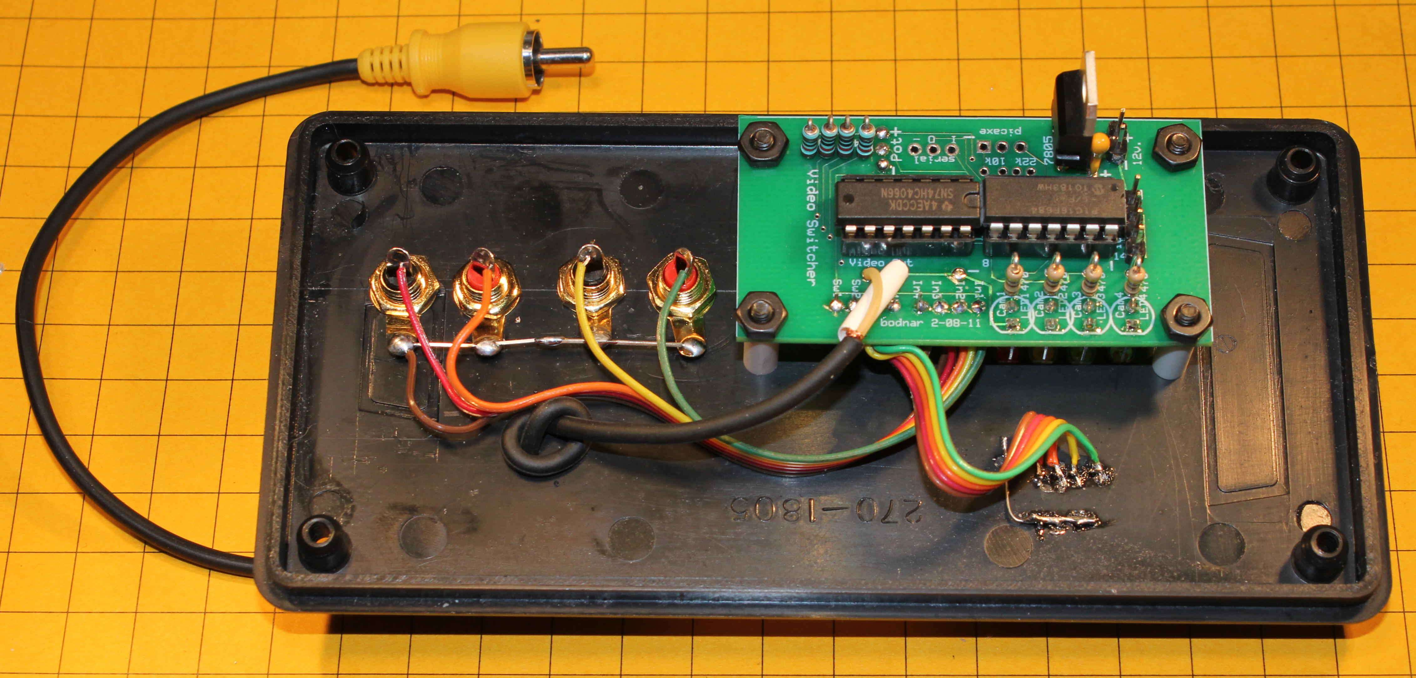
The photo below shows the board populated with the PIC 16F684, the 4066, four indicator LEDs with their current limiting resistors and the four pull up resistors for the camera selection switches. A small pot was installed temporarily for testing. The solder pads for the cameras (labeled In1--In4), the video output to the video capture unit (labeled Out) and for the switches (labeled Sw1--Sw4) can be clearly seen. <images/PIC_Board-3.jpg>
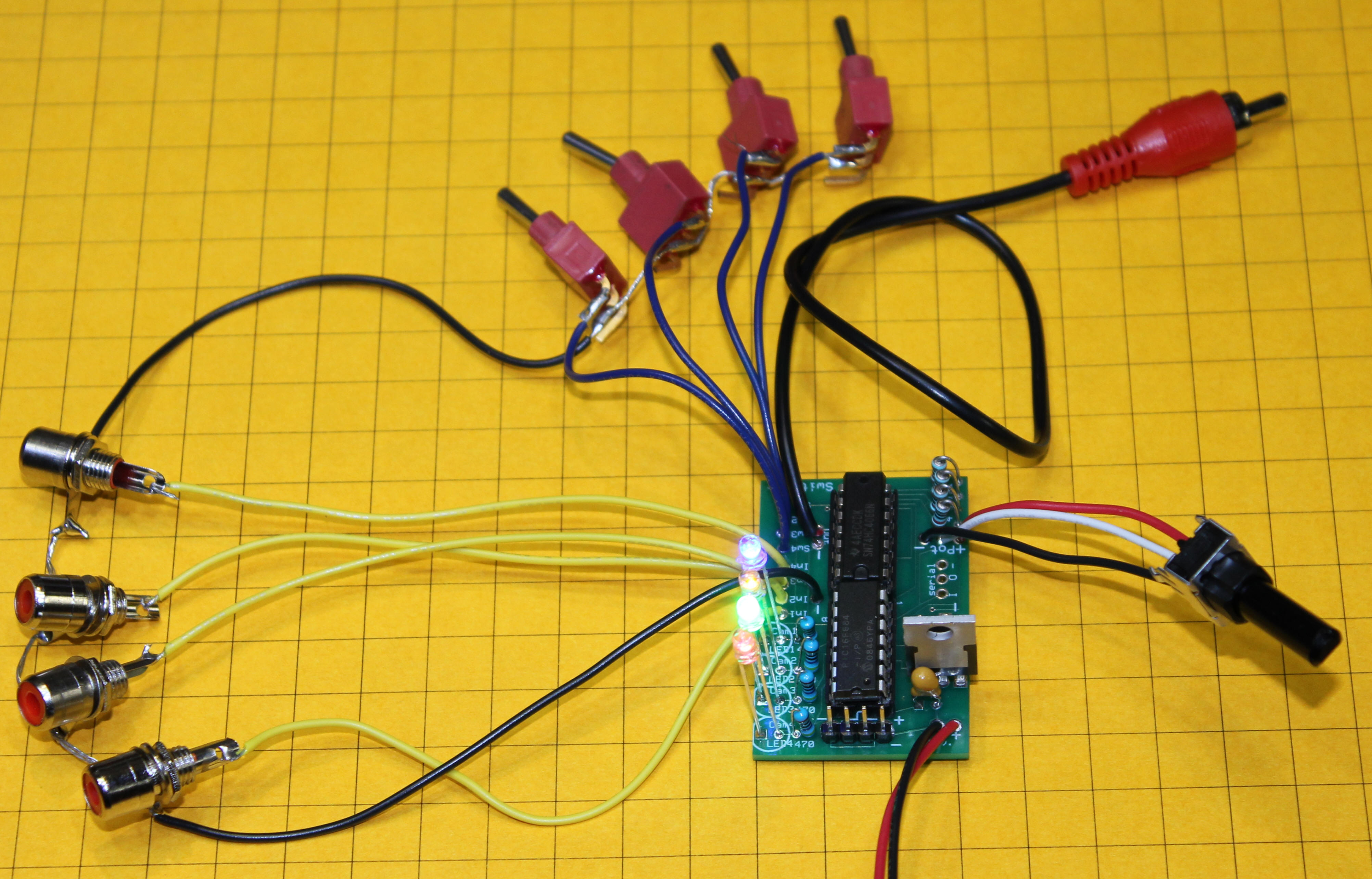
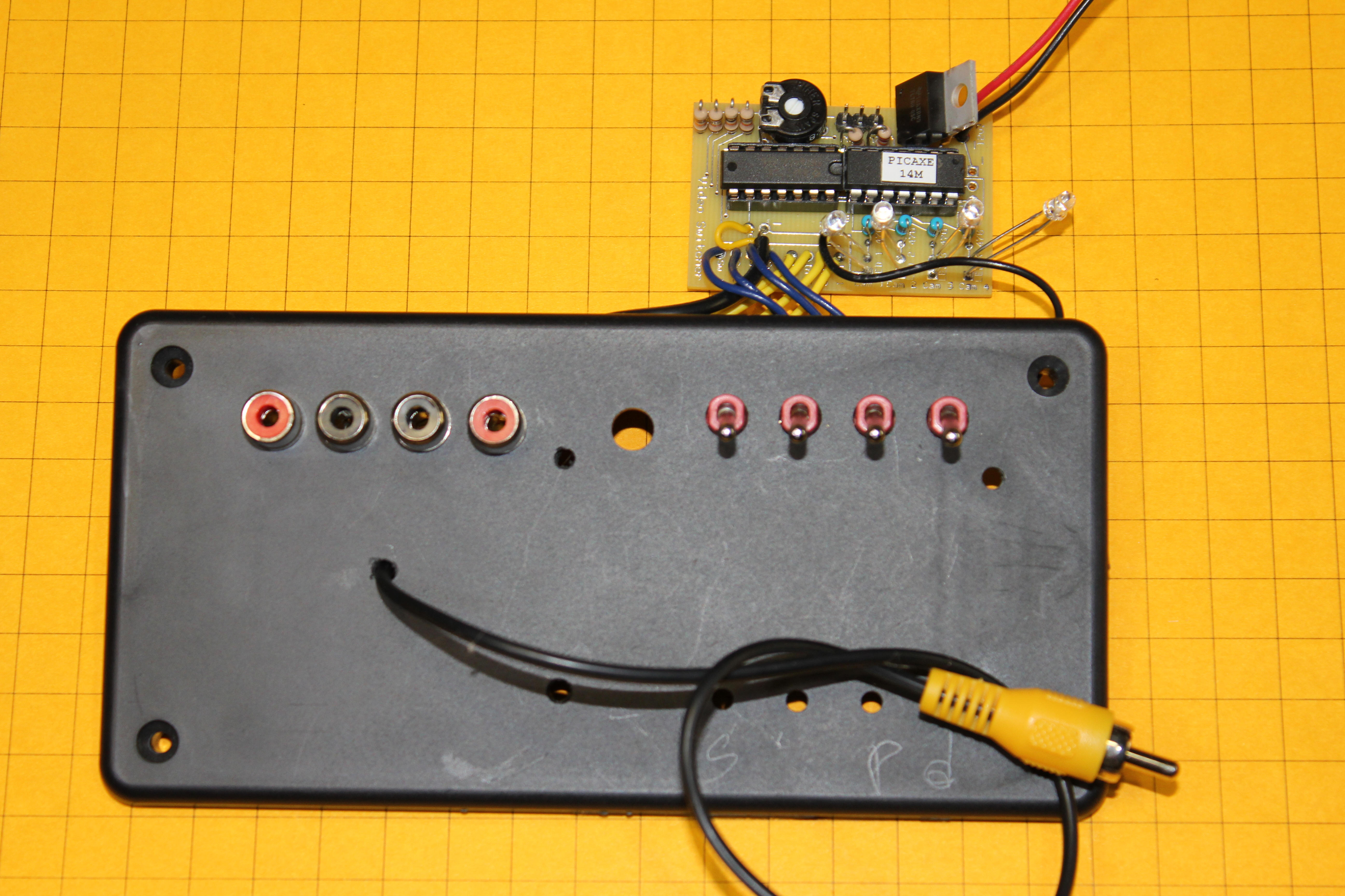
In this photo the switches, female RCA chassis mount jacks, male video output plug and potentiometer can be seen. <images/PICBoard-10.jpg>
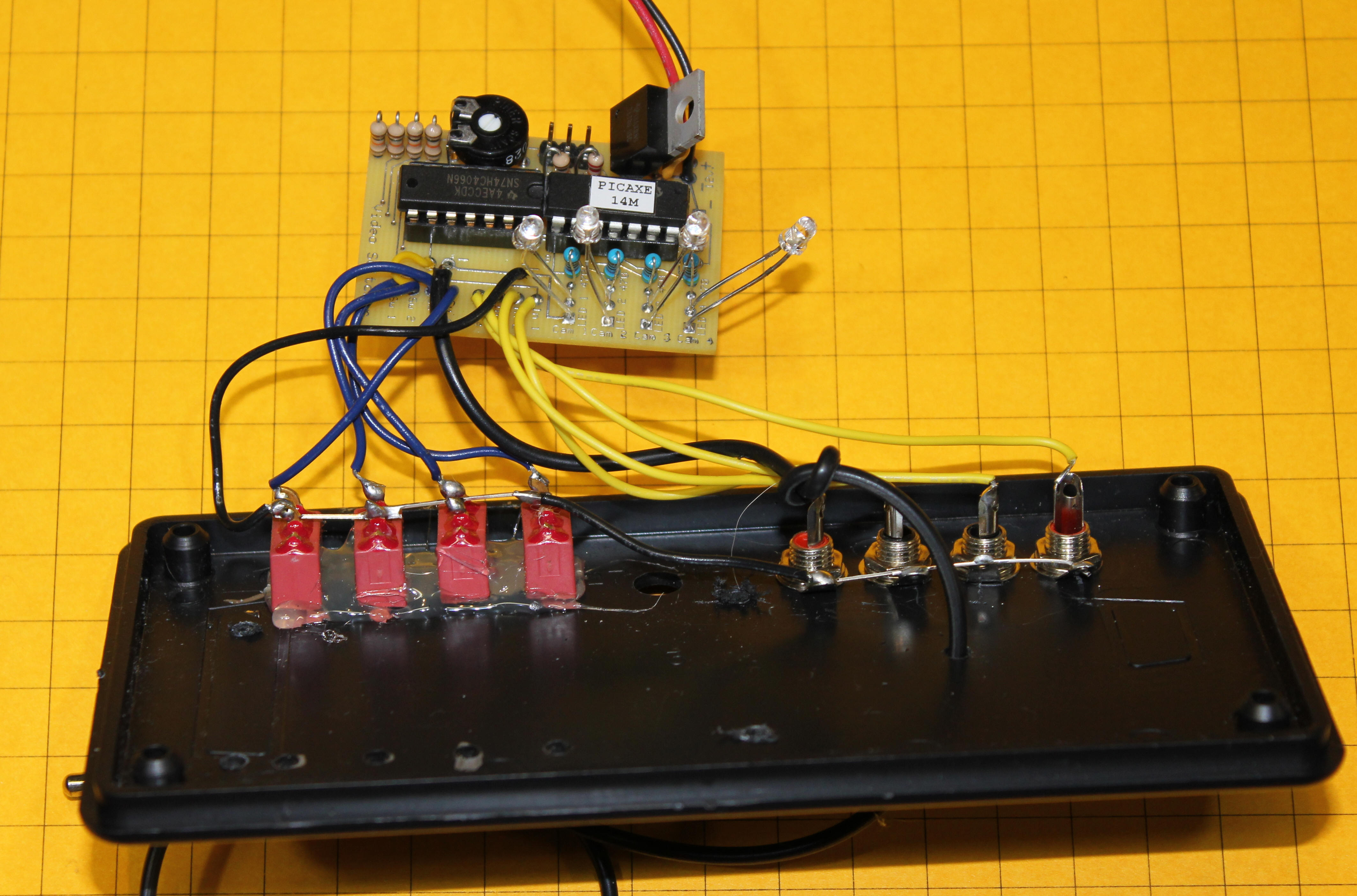
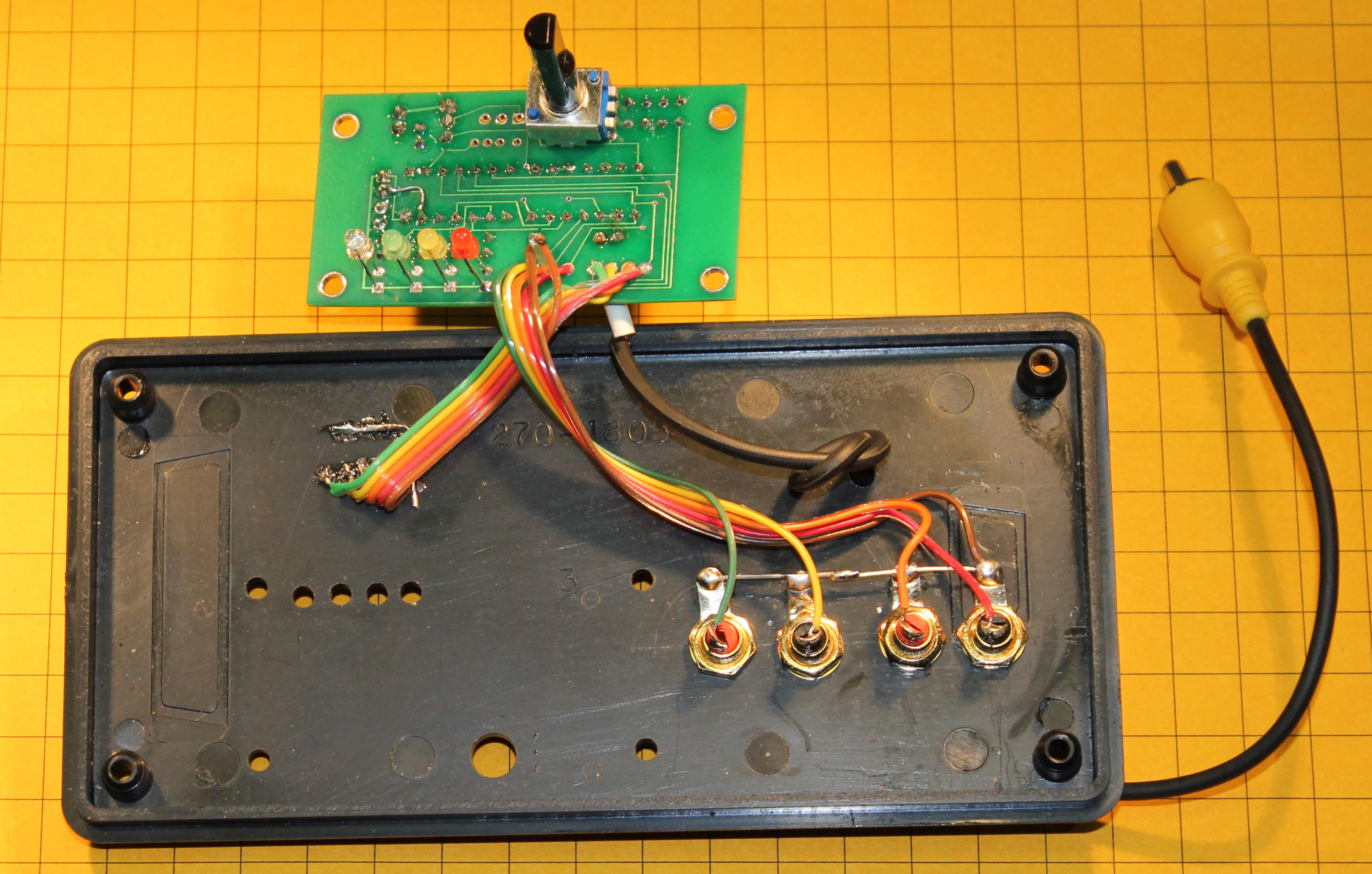
The photo below shows one of the first prototype units and the inside of the project box lid. <images/PIC_Board_Inside.JPG>
The yellow plug shown below goes to the USB / Video converter's video input. <images/PICAXE24.jpg>
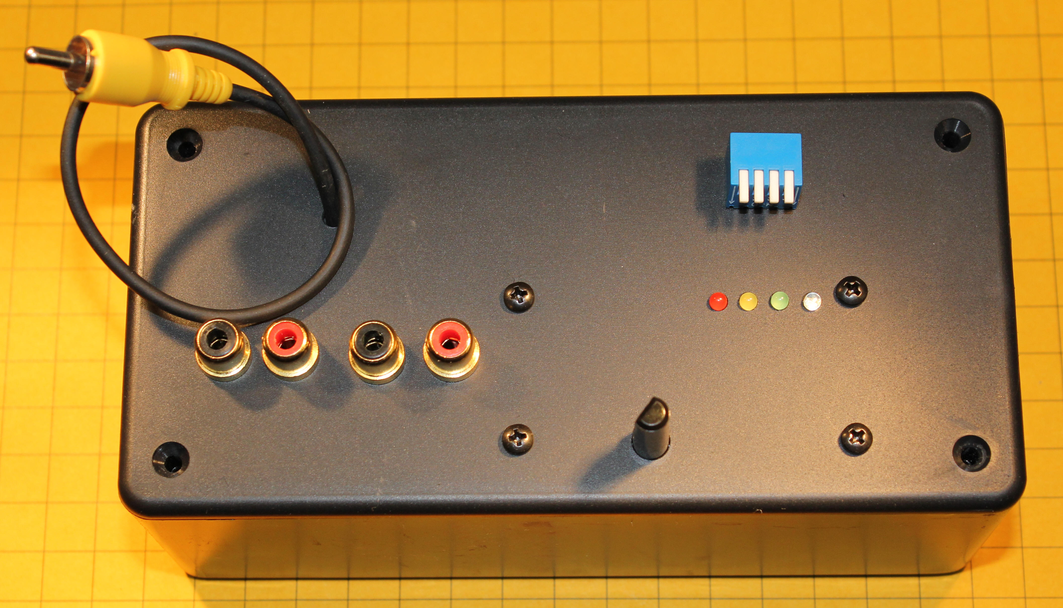
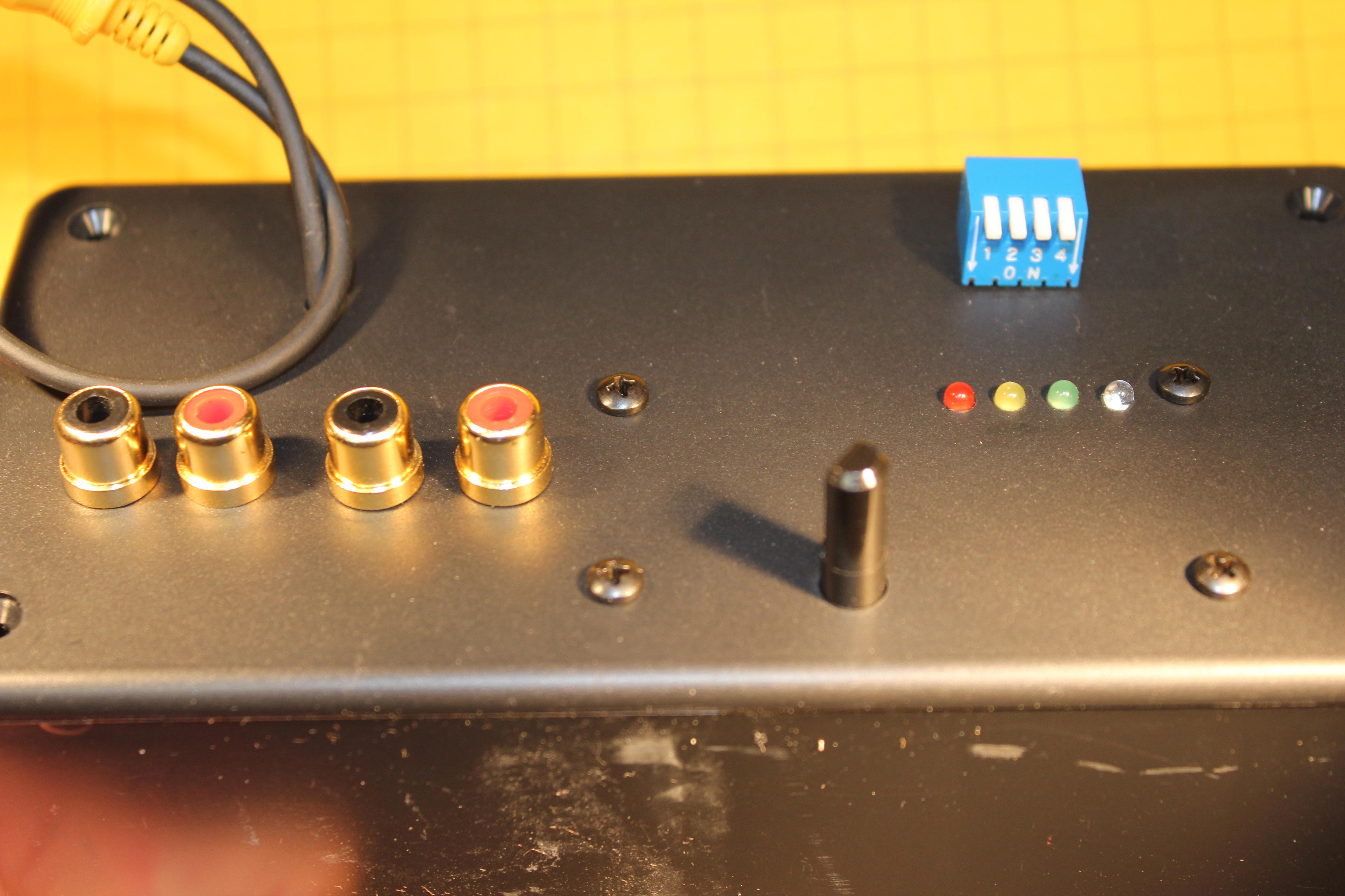
This photo shows another way that the circuit board can be mounted in a project box. The indicator LEDs and the potentiometer can be seen projecting through the top of the box. The blue object in the upper right corner is a four position DIP switch that is used to select which cameras are active. The four video input jacks are in the lower left and the video output plug is above them. <images/Complete_3.jpg>
This inside view shows that the LEDs and potentiometer have been soldered to the bottom of the circuit board to allow them to project through the top of the box. The pins from the DIP switch go through small holes in the box top and the wires that go to the circuit board are soldered directly to them. <images/Complete_1.jpg>
Here the circuit board has been screwed to the lid of the box with four bolts and plastic spacers. <images/Completed_6.jpg>
This close-up shows that the DIP switch levers need to be pushed down to activate a camera. <images/Complete_2.jpg>
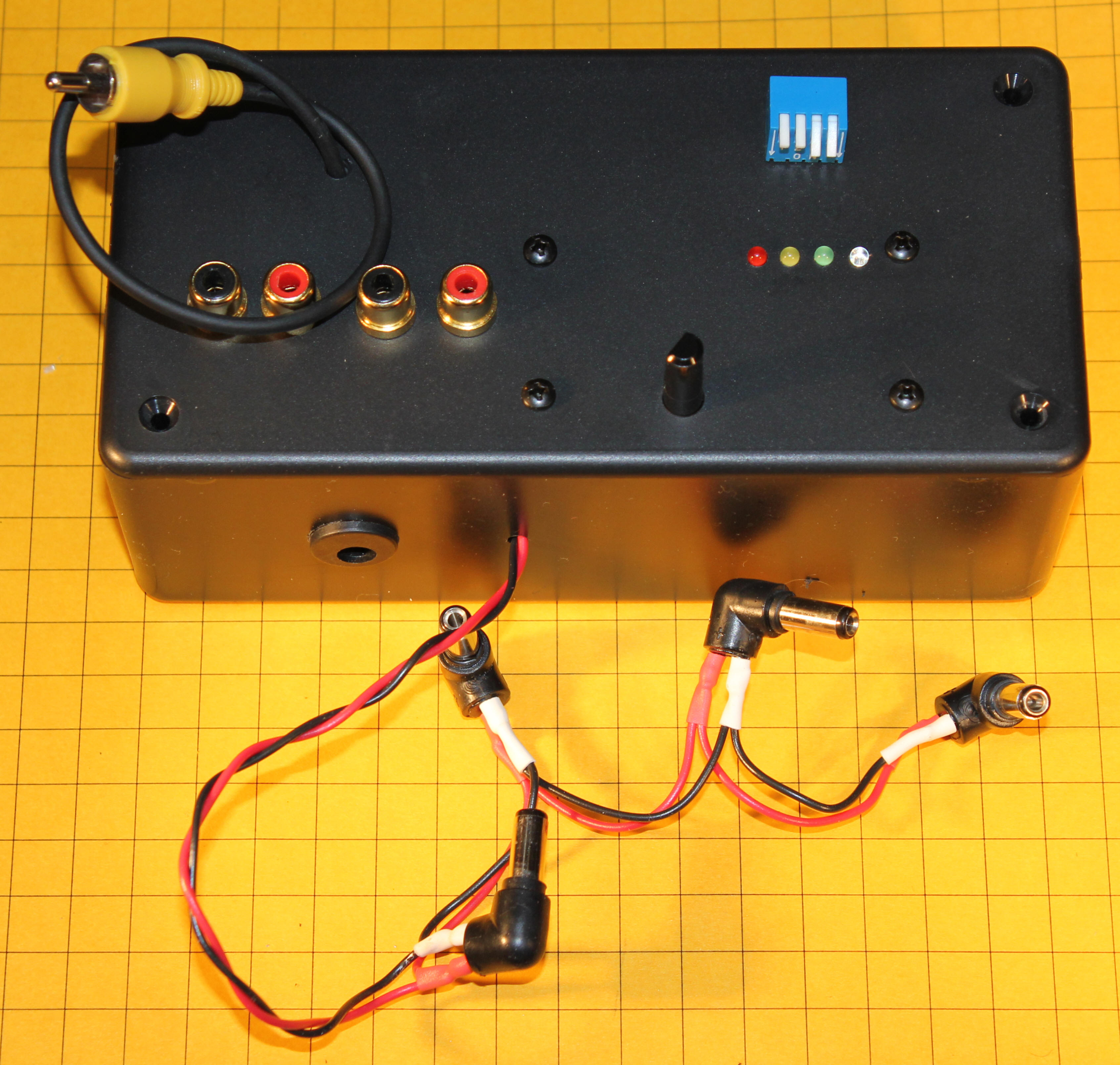
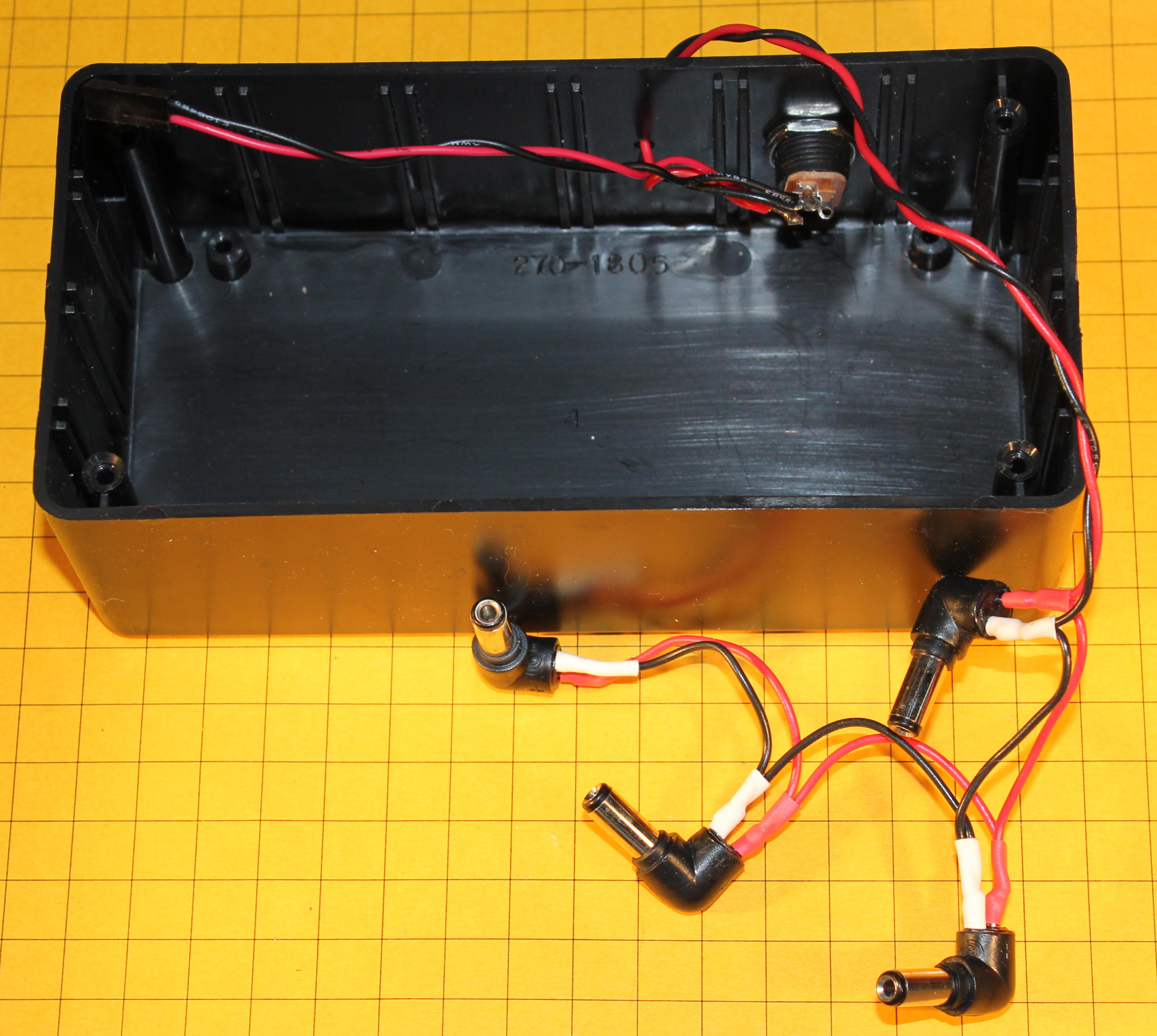
Rather than use four wall warts to power the four cameras I wired single, larger wall wart to four power connectors so that all of the cameras would work from one power supply. The supply that I used is rated at 2 amps @ 12 volts and is used for the video switcher and cameras. <images/Complete_4.jpg>
Power comes into the side of the base of the box. <images/Complete_5.jpg>
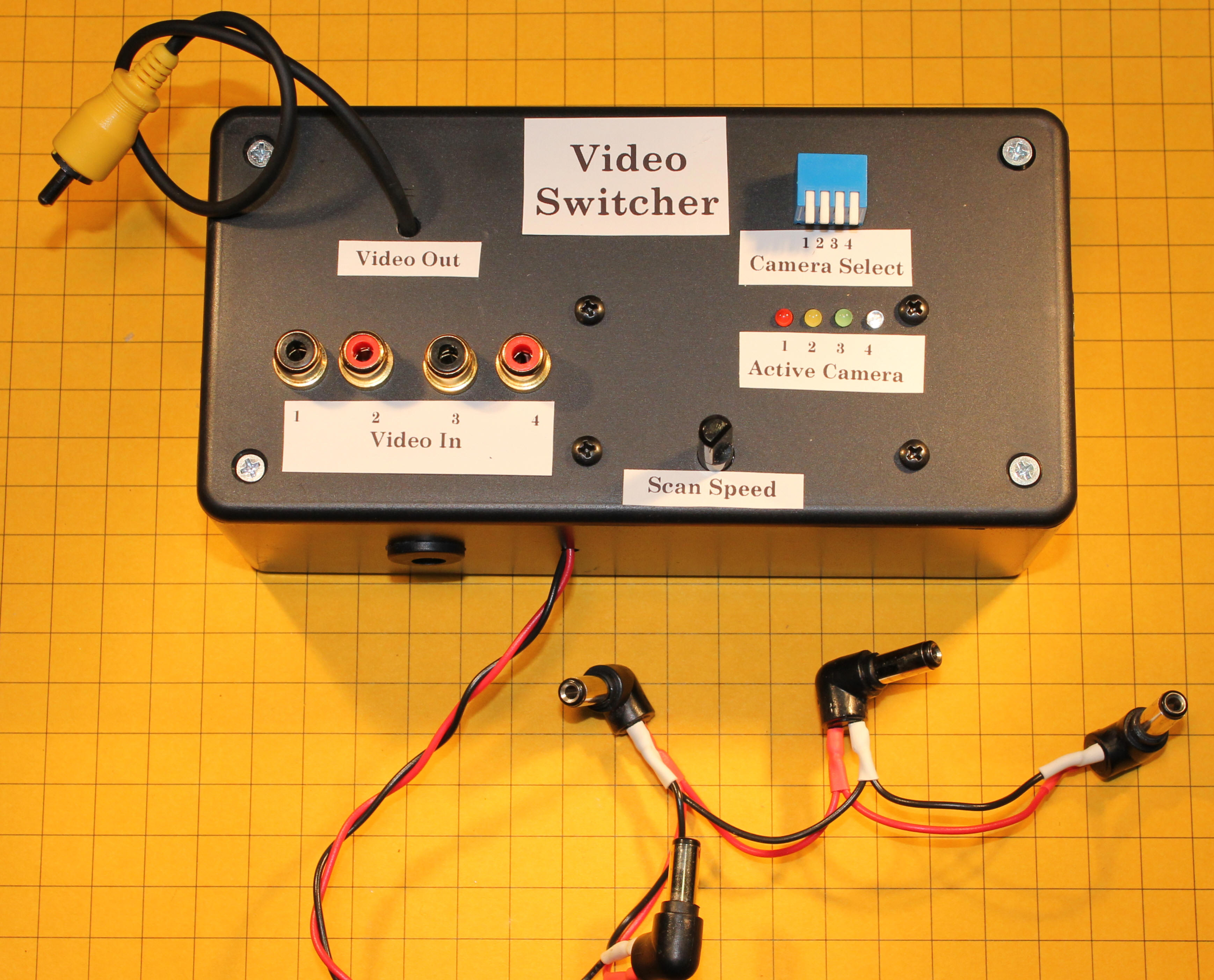
The completed unit is shown here with labels. <images/Completed_0.jpg>
|
| Cable Wiring This diagram shows the wiring of the Harbor Freight camera's cable. You can easily make a shorter cable for cameras that may be close to the switcher. It should also be possible to make a longer cable or extend the one that is included but video quality is likely to suffer. <images/PlugWiring.gif>
|
| Enhancements I have done some experiments with a servo based pan and tilt mechanism as well as with a pan and tilt unit marketed by the X-10 web site. Both worked and may become permanent additions to my home system. I have also configured the system to respond to web based control using a SitePlayer. That also worked but I have recently moved to a software based control system based on EZcom2web. If you visit my site the controls that are available are implemented with EZcom2web software. |
| Conclusion I have had the web cam system working for over a year and have come to rely on it throughout the day. It is really convenient to pull it up on my phone and check the cars in the driveway to see who is home or to make sure all is well around the house when on vacation. Others use it, too. I have had friends who travel south for the winter that check it from time-to-time to see how much snow is piling up in Pittsburgh! I believe that you may find it to be just as useful as I have. Give it a try and let me know if I can help (dave@davebodnar.com) |
|
Parts List
|