' d. bodnar -02-25-10 -Version 1.0 to test pulses to X10 Pan & Tilt Ninja Device
DEFINE DEBUG_REG PORTA
DEFINE DEBUG_BIT 0 ' PIN 8 on 16f88
DEFINE DEBUG_BAUD 9600
DEFINE DEBUG_MODE 1 ' Set 'DEBUG mode: 0 = true, 1 = inverted
ansel=0 'use pins as digital rather than analog
CMCON0= 7 'Disable comparator - makes portc LEDs work properly
DEFINE OSC 8 'use 8 mhz oscillator
OSCCON = $70 'set clock speed
INTCON = %00001100 '00xx11xx to be CCP1 mode
SerialOut VAR porta.0 'pin 13
NotUseda1 VAR porta.1 'pin 12
NotUsedc0 VAR portc.0 'pin 10
NotUseda3 VAR porta.3 'pin 4
NotUseda4 VAR porta.4 'pin 3
LEDPin11 VAR porta.2 'pin 11
LEDPin2 VAR porta.5 'pin 2
NotUsedc2 VAR portc.2 'pin 8
NotUsedc3 VAR portc.3 'pin 7
NotUsedc4 VAR portc.4 'pin 6
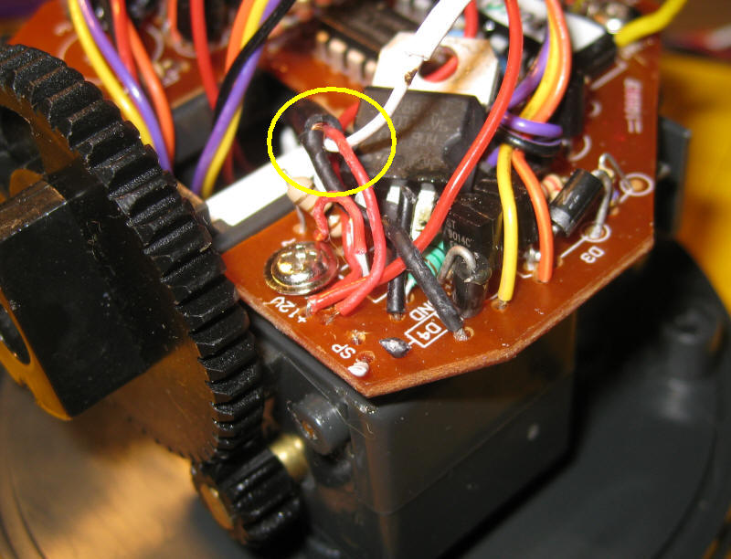
Signal VAR portc.5 'pin 5 ' output to pin 3 on Pan & Tilt processor
Loop VAR BYTE
Temp VAR BYTE
Temp2 VAR BYTE
A VAR WORD
B VAR WORD
K VAR BYTE
Rpt VAR BYTE
Counter VAR BYTE
trisa = %00000000
trisc = %00000000
DEBUG 10,13,"X-10 Pan & Tilt Test V1.0",10,13
DEBUG "(c) d. bodnar 02-25-10",10,13
Counter =0
Rpt = 125
Top:
FOR Temp2=1 TO 5
TOGGLE LEDPin11
DEBUG 10,13
SELECT CASE Temp2
CASE 1
DEBUG "left",10,13
A = $9560 'left
CASE 2
DEBUG "right",10,13
A = $9661 'right
CASE 3
DEBUG "center",10,13
A = $A16C 'center
CASE 4
DEBUG "up",10,13
A = $9762 'up
CASE 5
DEBUG "down",10,13
A = $9863 'down
END SELECT
Counter=Counter+1
DEBUG "@ Top ",#Counter," Case ",#Temp2," cmd ",#A,10,13
B = $0006 'always
IF A <> 0 THEN 'we have a valid command
FOR K = 1 TO Rpt
TOGGLE LEDPin2
GOSUB Sendcmd
DEBUG #K," "
PAUSE 10
NEXT K
DEBUG 10,13
ENDIF
PAUSE 1500
NEXT Temp2
GOTO Top:
'***Ninja command protocol****
'The start sequence is a 2.4ms pulse followed by a 1.6ms space. A 1-bit is a
'0.6ms pulse followed by a 1.6ms space and a 0-bit is a 0.6 ms pulse followed
'by a 0.6ms space. Only 20 bits of data are sent. A 0-bit marks the end of
'the frame. Repeats follow with no gap.
'See: http://davehouston.net/cr14a-rf.htm
'based on Bob Gardners code http://gardnerswebsite.com/ninjamods/index.html
' modified for PicBasicPro
Sendcmd:
 LOW Signal
 PAUSEUS 2400
 HIGH Signal
 PAUSEUS 2400
 LOW Signal
 PAUSEUS 1600

FOR Loop = 15 TO 0 STEP -1
    HIGH Signal
    PAUSEUS 600
    LOW Signal
     IF A.0(Loop) = 1 THEN
        PAUSEUS 1600
     ELSE
        PAUSEUS 600
     ENDIF
NEXT Loop

FOR Loop = 3 TO 0 STEP -1
 HIGH Signal
 PAUSEUS 600
 LOW Signal
 IF B.0(Loop) = 1 THEN
    PAUSEUS 1600
 ELSE
    PAUSEUS 600
 ENDIF
NEXT Loop

 HIGH Signal
 PAUSEUS 600
 LOW Signal
RETURN

END
|
'12-7-10 - revised to send pulses to x-10 pan/tilt unit
'IMPORTANT - set Config on programmer software to Oscillator INTOSCIO to use
    'pins 2 & 3 (makes them I/O rather than for oscillator)
' WORKING WELL (12-7) with Servo & X-10!!!!!!!!!!!
'11-28-2010 WORKING WELL WITH NEW GREEN BOARD UNIT

'11-26-10 - revised for proper order of cameras on green board
    'Servos working in test mode - range from 50 to 500 on pulsout for 180 degrees
'06-28-2010 - test for Web Cam - receives data from web server & sends back status
' via serial port @ 2400 baud

'notes 11-23-10 - working but sending data back to web server only after 3 refreshes
    'need to get that working better
    ' the good news is that the PIC gets the data on the first hit - nice!

'Need To:
'	revise for changes in new board
'	set up to work from pot only as well as PICAXE from pot and serial control
'	serial working using EZCom2Web software from laptop via pins 7 & 12

DEFINE DEBUG_REG PORTA
DEFINE DEBUG_BIT 0         ' PIN 8 on 16f88
DEFINE DEBUG_BAUD 9600
DEFINE DEBUG_MODE 1 ' Set 'DEBUG mode: 0 = true, 1 = inverted
ansel=0                 'use pins as digital rather than analog
CMCON0= 7               'Disable comparator - makes portc LEDs work properly
DEFINE OSC 8            'use 8 mhz oscillator
OSCCON = $70            'set clock speed
option_reg.7=0          'turn on weak pull ups
wpu = %00100000         'weak pull ups on pin GPIO.5 only
INTCON = %00001100        '00xx11xx to be CCP1 mode

SerialOut       VAR porta.0      'pin 13
xxxxxx          VAR porta.1      'pin 12
Camera1         VAR porta.2      'pin 11
Camera2         VAR portc.0      'pin 10
Camera4         VAR portc.1      'pin 9
Camera3         VAR portc.2      'pin 8  '
NotUsed4        VAR porta.3      'pin 4
Signal          VAR porta.5      'pin 2 - to pan/tilt unit
NotUsed3        VAR portc.2      'pin 3
Servo1          VAR portc.4      'pin 6  ' Small servo - up/down
Servo2          VAR portc.5      'pin 5  ' Large servo - left/right
SerialIn        VAR portc.3      'pin 7
SerialOut2      VAR porta.1      'pin 12
temp            VAR WORD
temp2           VAR WORD
Data2SendFlag   VAR BYTE        '=1 if there is data to send 0 if not
Loop            VAR BYTE
A               VAR WORD
B               VAR WORD
K               VAR BYTE
Rpt             VAR BYTE
Counter         VAR BYTE
 Delay	        VAR WORD
 Test		    VAR BYTE
 CommandIN	    VAR BYTE	'data from web page
 Loopie	        VAR WORD
 Loopie2        VAR WORD
 Cam1On	        VAR BIT	'=0 if off, =1 if on
 Cam2On	        VAR BIT
 Cam3On	        VAR BIT
 Cam4On	        VAR BIT
 ServoVar       VAR BYTE 'branch variable
 LeftRight      VAR WORD
 Tilt           VAR WORD
 TimeFudge	    CON 10
 DelayS         CON 100'servo delay
Tilt = 350
 Data2SendFlag=0
trisa            = %00000000
trisc            = %11000100

DEBUG 10,13,"WebCam Servo&X10 Test",10,13
DEBUG "(c) d. bodnar v4.2 12-07-10",10,13
temp2=0 :HIGH Camera1:HIGH Camera3

Delay=2*TimeFudge
Cam1On=1:Cam2On=1:Cam3On=1:Cam4On=1 'turn on all cameras

Start:
''toggle signal:pause 500:goto start
GOSUB Check4SerialData:

IF Cam1On=0 AND Cam2On=0 AND Cam3On=0 AND Cam4On=0 THEN
	GOSUB AllLow:
ENDIF

'IF UseCamera1=0 and Cam1On=1 THEN
IF Cam1On=1 THEN
	GOSUB AllLow:
	HIGH Camera1
	GOSUB DLay'PAUSE Delay
ENDIF

'IF UseCamera2=0 and Cam2On=1 THEN
IF Cam2On=1 THEN
	GOSUB AllLow:
	HIGH Camera2
	GOSUB DLay'PAUSE Delay
ENDIF

'IF UseCamera3=0 and Cam3On=1 THEN
IF Cam3On=1 THEN
	GOSUB AllLow:
	HIGH Camera3
	GOSUB DLay'PAUSE Delay
ENDIF

'IF UseCamera4=0  and Cam1On=1 THEN
IF Cam4On=1 THEN
	GOSUB AllLow:
	HIGH Camera4
	GOSUB DLay'PAUSE Delay
ENDIF
DEBUG "@ end",10,13

'GOsub sendserialdata:
GOTO start:

AllLow:
LOW Camera1:LOW Camera2:LOW Camera3:LOW Camera4':pause 10
RETURN

DLay:
FOR Loopie = 1 TO Delay
'debug #loopie
    'for loopie2=1 to 1
        GOSUB Check4SerialData:
    'next loopie2
NEXT Loopie
RETURN

Check4SerialData:
CommandIN=0
SERIN serialin, 6, 100,SkipOutNoData2,["ZZZ"],CommandIN    'REM 4=N2400  , 6=9600
CommandIN=CommandIN-64
DEBUG 10,13," I heard ",#CommandIN
'1 2 3 4 turn off cameras
IF CommandIN=1 THEN
	Cam1On=0
ENDIF
IF CommandIN=2 THEN
	Cam2On=0
ENDIF
IF CommandIN=3 THEN
	Cam3On=0
ENDIF
IF CommandIN=4 THEN
	Cam4On=0
	'debug "did 4 off",10,13
ENDIF
'5 6 7 8 turn on cameras
IF CommandIN=5 THEN
	Cam1On=1
ENDIF
IF CommandIN=6 THEN
	Cam2On=1
ENDIF
IF CommandIN=7 THEN
	Cam3On=1
ENDIF
IF CommandIN=8 THEN
	Cam4On=1
ENDIF

IF CommandIN=9 THEN
Delay = 1*TimeFudge	'1 second
ENDIF
IF CommandIN=10 THEN
Delay = 2*TimeFudge	'2.5 seconds
ENDIF
IF CommandIN=11 THEN
Delay = 5*TimeFudge	'5 second
ENDIF
IF CommandIN=12 THEN
Delay = 10*TimeFudge	'10 seconds
ENDIF
DEBUG 10,13,"CAMs = ",#Cam1On,#Cam2On,#Cam3On,#Cam4On," Dlay= ",#Delay,10,13 ," /10ths"

IF CommandIN>=13 AND CommandIN<=20 THEN
    GOSUB  specialservocommands:
ENDIF
IF CommandIN>=21 AND CommandIN<=35 THEN
    GOSUB specialX10commands:
ENDIF
'toggle camera1:toggle camera2:toggle camera3:toggle camera4
Data2SendFlag=1
'gosub skipoutnodata2
RETURN
SendSerialData:
DEBUG 10,13,"Cams = ",#Cam1On,#Cam2On,#Cam3On,#Cam4On,"  Dlay= ",#Delay,10,13
SEROUT SerialOut2,6,["Cameras = ",#Cam1On,#Cam2On,#Cam3On,#Cam4On,"  Delay= ",#Delay,"/10ths","<br>","Left/Right = ",#LeftRight," Tilt = ",#Tilt]',10,13]

RETURN

SkipOutNoData2:
IF Data2SendFlag=1 THEN
    GOSUB sendserialdata
    Data2SendFlag=0
ENDIF
DEBUG"."',#temp2,10,13
'goto start
RETURN


SpecialServoCommands:
DEBUG 10,13,"@SSC Cmd= ",#CommandIN,10,13
ServoVar=CommandIN-13 ' BRANCH statrt @ 0
BRANCH ServoVar, [PanRight, PanLeft, TiltUp,TiltDown,pond, railroad,DWpad, DWend]


PanRight: 'M 13
LeftRight=LeftRight+20
DEBUG"@ Pan Right ",#LeftRight,10,13
IF LeftRight > 480 THEN
    LeftRight=480
    RETURN
ENDIF
FOR temp=1 TO 10
  PULSOUT servo2, LeftRight
  PAUSE DelayS
NEXT temp
RETURN

PanLeft:    'N 14
LeftRight=LeftRight-20
DEBUG"@ Pan Left" ,#LeftRight,10,13
IF LeftRight <=20 THEN
    LeftRight=20
    RETURN
ENDIF
FOR temp=1 TO 10
  PULSOUT servo2, LeftRight
  PAUSE DelayS
NEXT temp
RETURN

TiltUp:    'O   15
Tilt=Tilt-50
DEBUG"@ Tilt Up ",#Tilt,10,13
IF Tilt < 220 THEN
    Tilt=220
    RETURN
ENDIF
FOR temp=1 TO 10
  PULSOUT servo1, Tilt
  PAUSE DelayS
NEXT temp
RETURN

TiltDown:   'P   16
Tilt=Tilt+50
DEBUG"@ Tilt Down ",#Tilt,10,13
IF Tilt > 480 THEN
    Tilt=480
    RETURN
ENDIF
FOR temp=1 TO 10
  PULSOUT servo1, Tilt
  PAUSE DelayS
NEXT temp
RETURN

Pond:     'Q  17
DEBUG "@ PND",10,13
LeftRight= 80 'lower #s cause servo to vibrate @ end
FOR temp=1 TO 20
  PULSOUT servo2, LeftRight
  PAUSE DelayS
NEXT temp
GOTO Start

Railroad:   'R  18
DEBUG "@ RR",10,13
LeftRight= 200
FOR temp=1 TO 10
  PULSOUT servo2, LeftRight
  PAUSE DelayS
NEXT temp
RETURN

DWpad:   'S  19
DEBUG"@ DW Pad",10,13
LeftRight= 345
FOR temp=1 TO 10
  PULSOUT servo2, LeftRight
  PAUSE DelayS
NEXT temp
RETURN

DWend:  'T  20
LeftRight= 400
DEBUG"@ DW End",10,13
FOR temp=1 TO 20
  PULSOUT servo2, LeftRight
  PAUSE DelayS
NEXT temp
RETURN

'**********Ninja command protocol**********
'The start sequence is a 2.4ms pulse followed by a 1.6ms space. A 1-bit is a
'0.6ms pulse followed by a 1.6ms space and a 0-bit is a 0.6 ms pulse followed
'by a 0.6ms space. Only 20 bits of data are sent. A 0-bit marks the end of
'the frame. Repeats follow with no gap.
'See: http://davehouston.net/cr14a-rf.htm
Sendcmd:
 LOW Signal
 PAUSEUS 2400
 HIGH Signal
 PAUSEUS 2400
 LOW Signal
 PAUSEUS 1600

FOR Loop = 15 TO 0 STEP -1
    HIGH Signal
    PAUSEUS 600
    LOW Signal
     IF A.0(Loop) = 1 THEN
        PAUSEUS 1600
     ELSE
        PAUSEUS 600
     ENDIF
NEXT Loop

FOR Loop = 3 TO 0 STEP -1
 HIGH Signal
 PAUSEUS 600
 LOW Signal
 IF B.0(Loop) = 1 THEN
    PAUSEUS 1600
 ELSE
    PAUSEUS 600
 ENDIF
NEXT Loop

 HIGH Signal
 PAUSEUS 600
 LOW Signal
RETURN

END

specialX10commands:
DEBUG 10,13,"@SSC Cmd= ",#CommandIN,10,13
ServoVar=CommandIN-21 ' BRANCH starts @ 0
BRANCH ServoVar, [leftX10, rightX10, upX10,downX10,mem1, mem2,mem3, mem4, Center, Sweep]


leftX10:
   DEBUG "l",10,13
     A = $9560 'left
GOTO X10_done:
rightX10:
       DEBUG "r",10,13
     A = $9661 'right
GOTO X10_done:
upX10:
       DEBUG "u",10,13
     A = $9762 'up
GOTO X10_done:
downX10:
       DEBUG "d",10,13
     A = $9863 'down
GOTO X10_done:

Mem1:
       DEBUG "M1",10,13
     A = $9964 'Memory 1
GOTO X10_done:
Mem2:
       DEBUG "M2",10,13
     A = $9B66 'Memory 2
GOTO X10_done:
Mem3:
       DEBUG "M3",10,13
     A = $9D68 'Memory 3
GOTO X10_done:
Mem4:
       DEBUG "M4",10,13
     A = $9F6A 'Memory 4
GOTO X10_done:
Center:
       DEBUG "c",10,13
     A = $A16C 'center
GOTO X10_done:
Sweep:
       DEBUG "Swp",10,13
     A = $A36E 'sweep
GOTO X10_done:
X10_done:

'counter=counter+1
'''debug "@ Top ",#counter," Case ",#temp2," cmd ",#a," Repeat= ",#rpt,10,13
B = $0006 'always
'a=$9762'up
'a=$9863'down
'a=$A16C'center

Rpt = 25

IF A <> 0 THEN 'we have a valid command
 FOR K = 1 TO Rpt
' toggle ledpin2
 GOSUB Sendcmd
 DEBUG #K," "
 PAUSE 10
 NEXT K
 DEBUG 10,13
ENDIF
RETURN
|