Block Control
revised 11-1-06
When using track power we frequently find a need to electrically separate sections of track from one another, creating areas where power can be removed or changed to create some desired effect. In the project that I introduced in the last article isolated blocks of track are needed for two reasons.
First, power is to be applied to only one engine at a time. The other engines must wait their turn to move outside of the garage and run through the garden. Isolated blocks provide an ideal way to accomplish this.
In addition there is a need to reduce the speed of trains operating within these blocks so that they can be controlled and detected more reliably. Once blocks are established power change within them is possible.
Insulated Rail Joiners
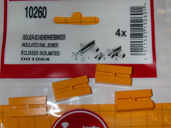
The simplest way to isolate a section of track is to remove one rail joiner from each end of the block and replace it with an insulating, plastic rail joiner such as LGB’s 10260...
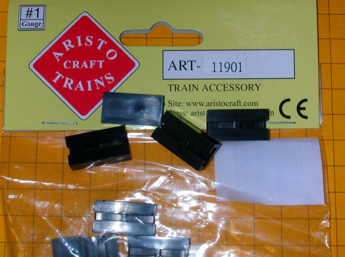
or AristoCraft’s 11901...
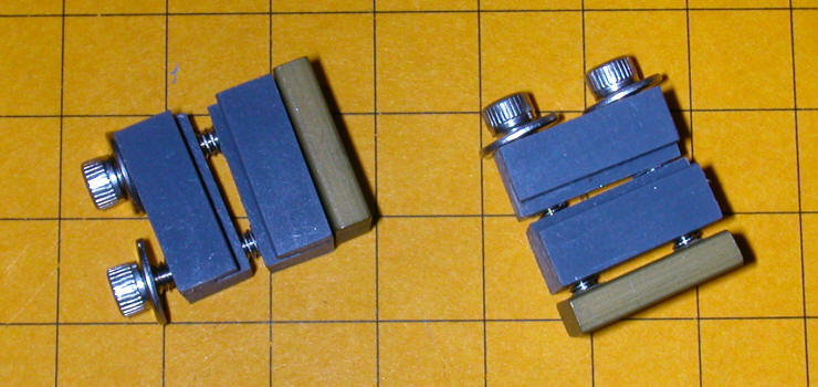
or with Hillman Rail Clamp's #332-01PSA .
In order to get power to the isolated section you can use standard track power connectors such as LGB’s 50161 or Hillman Rail Clamp's #332-015 . If you would prefer to “do it yourself” you can try the method described here. I have used it quite successfully to insert diodes into cut track sections at each end of point-to-point track run that is controlled by my BARC auto-reverse controller (see article: Basic Auto-Reverse Control )
Making Your Own Insulated Track Sections
This method works best if you place the cut near the center of a 12” or longer piece of track. Use a Dremel with an abrasive cutting wheel, a band saw or a hack saw to cut through one of the rails. It is easier to cut at a slight angle, as seen below, when using the Dremel.
.JPG)
Take care not to cut through the plastic that joins the ties as it helps to strengthen the cut section of track.
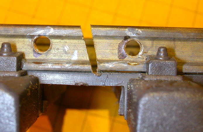
You will note that there are holes on either side of the cut that is being made in the photo above. Although they will be explained in more detail below it is important to note here that they are MUCH easier to drill before cutting the track.
On LGB and AristoCraft track I like to turn the track over after cutting so that I can fill the holes under the ties on either side of the cut with 5 minute epoxy to further strengthen the cut area.
Find a nylon cable tie that is about as thick as the cut in the rails. Coat its end with 5 minute epoxy and force it into the opening.
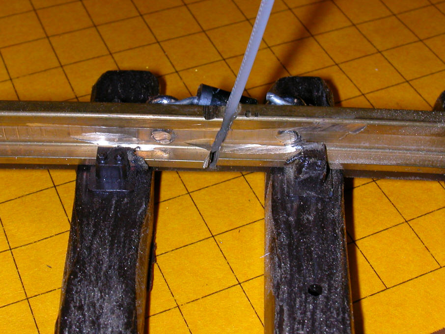
After the epoxy dries cut off and file smooth the excess cable tie that extends above the track
Making Your Own Power Connections
You can make power connections in a number of ways. The quickest, and least reliable, is just to force a piece of stripped wire between the bottom of the rail and the plastic section under it. Adding a spade terminal to the end of the wire makes for a much more secure and reliable connection. It certainly isn't a permanent solution but works surprisingly well on temporary installations.
A much more secure and reliable connection can be made by installing a screw through the rail and using that to fasten the power cable. You can take the time to drill a hole, tap it for a screw size that you have available and using that to connect the wire. I have found a simpler, faster method that utilizes self drilling screws.
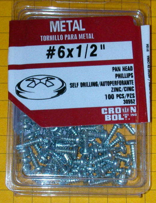
Self drilling screws have been popular for years in the construction industry where they are used in sheet metal work and to attach metal studs together. They are similar to a standard self tapping screw but with an important difference. The tip has been fashioned into a hardened metal drill. You can use one of these screws and any power drill’s screwdriver bit to drill a hole and fasten the screw in place in one quick operation.
If you are using brass track these screws make short work of connecting power to the track.
Mark the rail where you would like to have the connection, place the self drilling screw’s point there and start it spinning with your drill. Please don't try this unless the track is being held in a vise as you must exert a good bit of downward force to get the drill started. If you have trouble getting the hole started drill a 1/16" pilot hole first.
.JPG)
Use firm steady pressure and a medium speed on the drill.
.JPG)
You be through the rail in a jiffy!
.JPG)
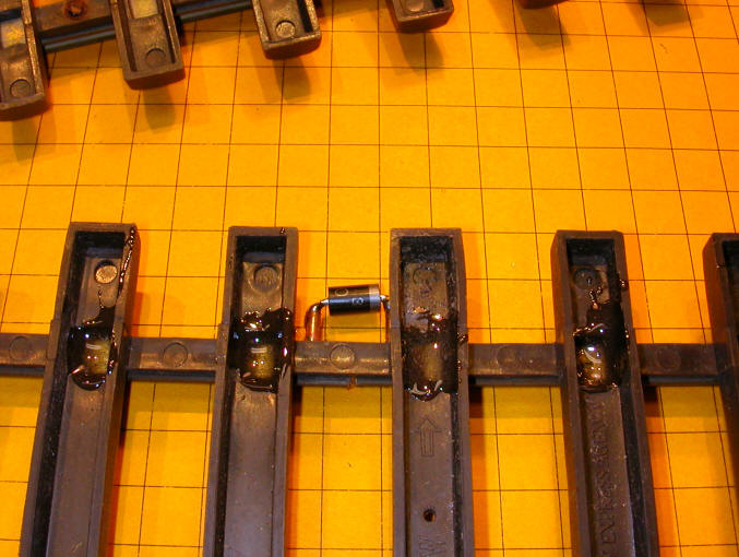
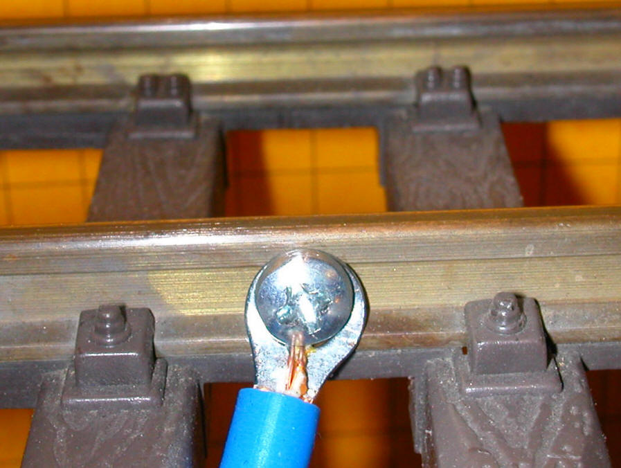
The next step is to attach your wire being sure to loop it around the screw in a clockwise direction so that tightening the screw tightens rather than unwraps the wire. In this photo this method is being used to attach a diode for the auto reverse point-to-point.
.JPG) <
<
A good bit of the screw will extend through the rail as you can see above. Cut it off flush with the inside of the track with a Dremel.
.JPG)
Several other suggestions are in order. If you use this method on a piece of cut track it is important that you drill the holes and insert the screws before you cut the track. It is much stronger and tolerates being drilled much better before being cut. If you are going to use this method on track that will be outside you may want to replace the self drilling screws, which are usually prone to rusting, with the same size stainless steel self tapping screws. Just use the steel ones to drill and tap the holes, back them out, insert the stainless steel ones and cut flush.
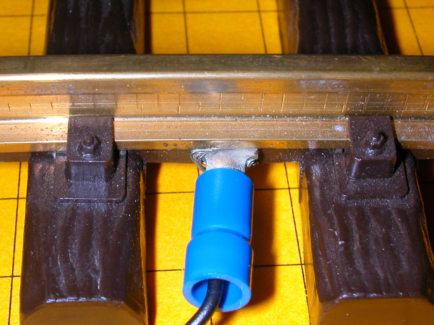
Finally, it is easier to make the connection between the wire and the track if you terminate the wire in a crimp-on or solder-on terminal.
A Basic Layout Using Blocks
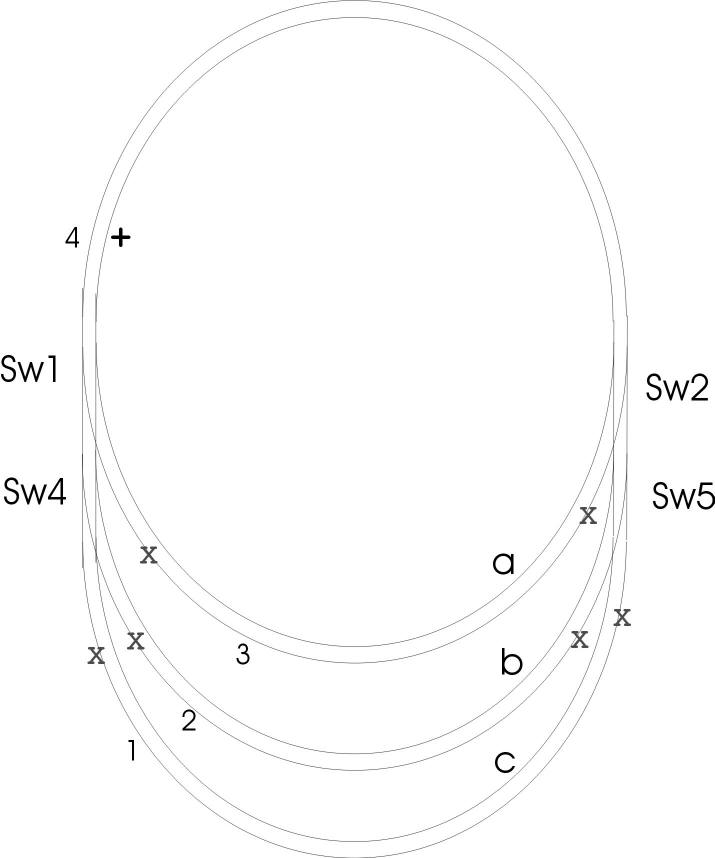
The simplified diagram below shows three isolated sidings, labeled "a", "b" and "c". Each "x" indicates a place where the track has been cut and an insulator installed. Note that all cuts are on the outer rail of each section.
Supplying Power to the Blocks with Switches
The simplest way to make use of the blocks that are shown above is to make the following connections:
Attach track power to some point on the main loop above the switches. The points on the drawing marked with "4" and "+" are appropriate. Attaching the negative terminal of your DC power supply to point 4 and the positive terminal to point "+" will have your G-scale trains run counter clockwise, the direction ours must run for this project to work properly.
Connect the for wires to three single-pole-single-throw (SPST) toggle or push button switches as is illustrated below:

With power applied to the outer loop you can individually power any of the blocks by throwing the appropriate switch.
This is similar to what will happen in this project except that the PICAXE microcontroller will be "throwing" the switches using the relays described next.
Supplying Power to the Blocks with Relays
I am normally not a big fan of relays, preferring to use electronic devices that have no moving parts or contacts to wear out. There are places, however, where relays are a good way to get the job done. They are ideal for a number of reasons:
Relays are usually reasonably priced
Relays don’t care about the polarity of the voltage that flows through their contacts
Relays are available that will handle more power than we are ever likely to use with model trains.
(note: A future article will deal with using completely electronic means to control blocks.)
What, Exactly, Is a Relay?
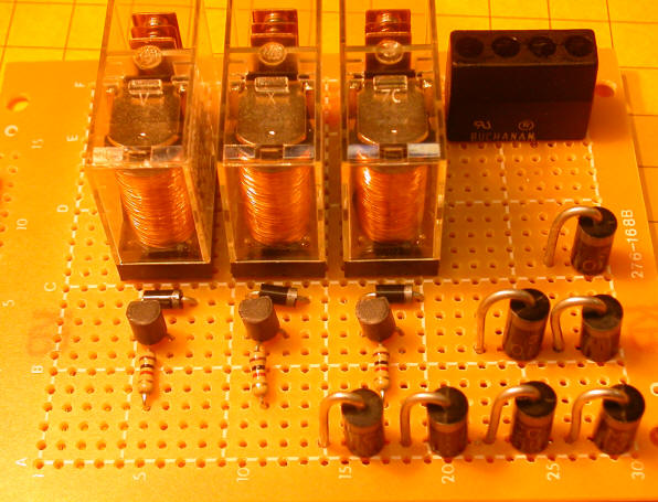
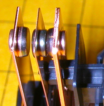
A relay is an electro-mechanical device that is made up of an electromagnet and a metal plate that will, when the electromagnet is on, connect or disconnect one or more sets of contacts. Think of it as a push button switch that is activated by an electromagnet. In the photo below the coil and metal plate are on the right and the three contacts that make up a SPDT switch are at the left.
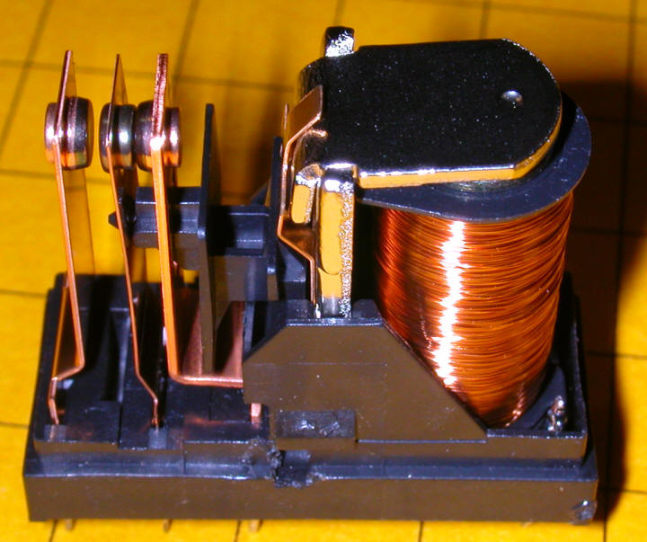
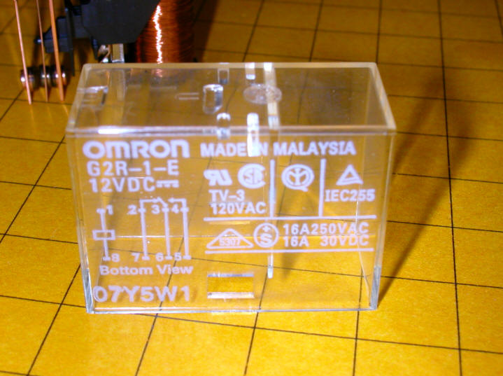
The first two characteristics of a relay that are important to us are the rating of the contacts and their arrangement. Contacts are rated by the voltage and current that they can handle. The relays I have selected for this project are rated at 16 amps at 30 volts DC, much more power than we are ever likely to use. The other important relay characteristic is the voltage and current that the coil of the electromagnet needs to move the switch contacts. The relays used here have 12 volt coils and draw about 100 milliamps when activated. The photo below shows the relay's cover. Note the information that it provides.
The switch contacts are single pole, double throw. The relay's three contacts can be seen clearly below. The center contact is held to the right by a spring, as in this photo, when the coil is not activated. When the relay is activated the center contact moves to the left, breaking the connection with the right hand contact and making a connection with the one on the left.
We will be activating the relays with the output of the pins of our PICAXE. The PICAXE can deliver up to 5 volts at a maximum of 20 mA, much less voltage and current than the relay requires. The simplest solution is to have the PICAXE trigger a small transistor that will then activate the relay. The schematic below shows a relay along with the 2N2222 driver transistor. Note that any general purpose NPN transistor could be used.
In order to activate our relay a positive voltage (such as the +5 volts from the PICAXE) is applied to the base connection (b) of the 2N2222 through resistor R4. This turns the transistor on and allows current to flow between the transistor's collector (c) and emitter (e) providing a path to ground for the relay activating its coil. When the 5 volts is removed the path to ground is removed and the relay opens. The diode, D3, is necessary to protect the transistor from the surge that is produced when the power is removed from the relay's coil.
The relay's three contacts are at the top of the diagram. One is labeled NC, for normally closed and one is labeled NO, for normally open. The center, unlabeled contact is the common contact that moves between the NC and NO contacts as power is applied or removed from the coil..
In the photo below is the same circuit that is in the schematic. A LED has been added to show when the relay is active. It is connected through the common and NO contacts so that it lights only when the relay has been turned on.
The second row of holes from the top is connected to a source of +12 volts and the top row is connected to the negative terminal of the power source. The blue wire between +12 volts and the resistor is not connected, the relay is open and the LED is not lit.
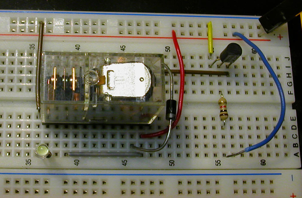
Here the blue wire is connected and, if you look very closely, the terminals on the relay have moved to the left lighting the LED.
.JPG)
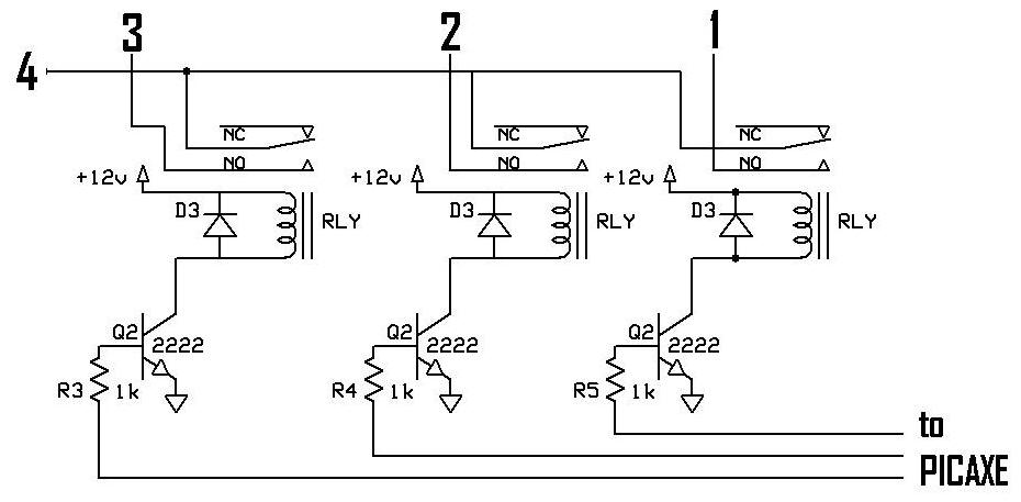
Using 3 Relays to Replace 3 Switches
In this schematic there are three identical relay circuits that will replace the three switches that were used earlier. Our blocks, which we wire to points 1, 2 and 3, are connected to the NO contact so that power will not be applied to a block until the relay is activated. The common contacts are all wired together and go to point 4 on the track. Whenever 5 volts from the PICAXE is applied to one of the resistors, R3, R4 or R5, the relay's coil closes the contacts activating the block.
To Be Continued...
Now that we can electronically control the power to each of the blocks the next step is to be able to use the PICAXE to throw switches. This will be the subject of the next installment. Stay tuned!