Diode Train Speed Control
revised 11-30-06
One of the design objectives of the automatic switch / block control system that has been the focus of these articles is that the trains entering the block control area would be automatically slowed down from their outside speed so that the risk of derailment and missed sensors would be reduced. This section shows a simple way of controlling speed in such situations.
Silicon Diodes
Common silicon diodes have an unusual characteristic that can be exploited to allow us to automatically adjust the speed of our track powered trains. Let's set up a few experiments to explore this. If a diode is put into a DC circuit between a power source and a motor one of two things will happen. If the diode is inserted with the banded end (the cathode) towards the positive side of the power supply the motor will stop completely as diodes in this orientation block the flow of electrons.
If the diode is reversed current will flow and the motor will spin. There will be one change, however. If the voltage across the motor is measured before the diode is inserted it will be about the same as the supply voltage. With the diode inserted the voltage across the motor will be about 0.7 volts lower than the supply voltage and the motor will run a bit more slowly.
Additional diodes, inserted in series, will each drop the voltage available to the motor by 0.7 volts. Each diode slows the motor just a bit but a string of 7 diodes, for example, decreases the speed of the motor significantly as the voltage drops by nearly 5 volts.
Adjustable Speed Change
An easily adjustable set of diodes can be made from the arrangement above. Three SPST (single pole single throw) switches can be placed as below so that throwing different combinations can drop the track voltage in 0.7 volt steps from a 0 volt drop to a 4.9 volt drop.
If all three switches are turned off, as is shown above, seven diodes are in the circuit dropping the voltage available to the engine by 4.9 volts. If switch 4 is closed it shorts out and bypasses the last 4 diodes, dropping the voltage by only 2.1 volts. The table below shows the voltage drops applied by different switch settings.
Note that the switches are labeled 1, 2, and 4 with the switch number representing the number of diodes controlled by that switch. (For those of you who are mathematically inclined does the arrangement of switches and the switch settings below remind you a bit of the binary number system?)
|
Switch 1 |
Switch 2 |
Switch 4 |
Diodes |
Voltage Drop |
|
on |
on |
on |
0 |
0.0 |
|
off |
on |
on |
1 |
0.7 |
|
on |
off |
on |
2 |
1.4 |
|
off |
off |
on |
3 |
2.1 |
|
on |
on |
off |
4 |
2.8 |
|
off |
on |
off |
5 |
3.5 |
|
on |
off |
off |
6 |
4.2 |
|
off |
off |
off |
7 |
4.9 |
This arrangement works well in the application that I am working on since the trains are always going in a counter clockwise direction and the polarity of the track power never changes. If you had any of the three switches above open and you tried to reverse the direction of your engine it would not move since the diodes in the circuit would block current flow.
Accommodating Forward and Reverse Running Trains
To get around this problem and allow trains to run in either direction we just have to double the number of diodes and wire them back-to-back as is shown below.
With this arrangement the voltage will be dropped, as before, but trains will run in forward or reverse.
Layout Wiring
In the layout that I have been describing, diagramed below, a set of diodes was installed between the main power feed from the part of the layout that is always powered and the connection that brings power to the individual blocks. This inserts the same voltage drop into the system for all three blocks but allows trains in the main loop to run at full speed.
In the schematic below the lead labeled "To Track Power" connects to the track where it is labeled "4" The isolated block connections go to the points numbered 1, 2 and 3.
Nudging Ahead
If you are wondering about the other three switches, labeled SW1, SW2 and SW3, they were added to allow quick alignment of trains when they were not in quite the right spot to block a sensor. Briefly pressing one of these momentary switches sent power to the block to move its engine up just a bit. This turned out to be a real time saver!
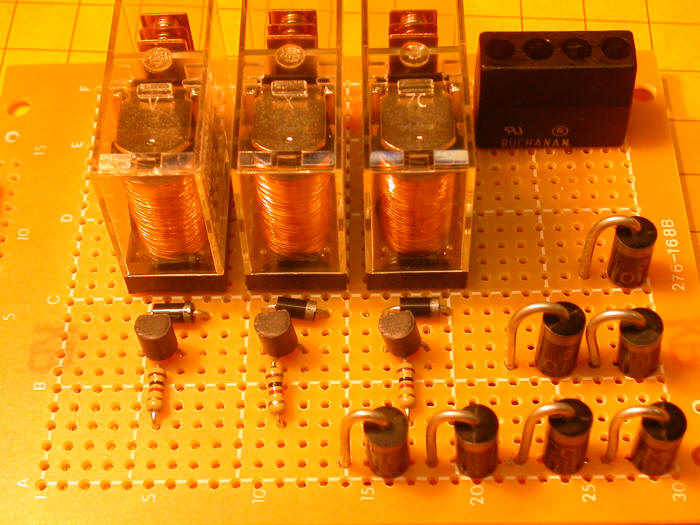
In this photo you can see the seven diodes, in groups of 4, 2 and 1. External switches were added to this board to allow selection of a voltage drop between 0 and 4.9 volts.
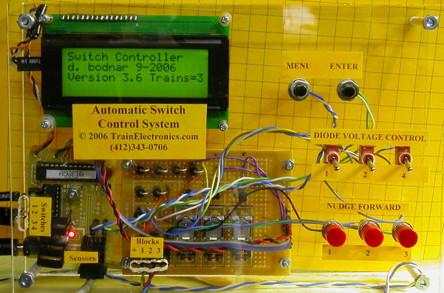
The photo below shows the completed controller. Note the "Diode Voltage Control" switches and the "Nudge" switches just below them.
Building a Diode Speed Drop Unit
Let's take a look at how a simple diode speed control unit can be constructed and added to your railroad. The parts that you need, listed at the end of this article, are readily available from sources such as Radio Shack and a number of other vendors. I have a list of those that I use listed on my web page at http://davebodnar.com/.
The first step is to determine how to lay out the circuit.
I decided to drill holes for each diode in a 5" x 6" piece of 1/8" thick
Plexiglas. You could use wood, circuit board or just about any
non-conducting material. The bent diodes fit nicely into holes that are on
2/10" centers. To lay out the drilling I printed up a piece of graph paper
with 2/10" squares. There is no need to go to the store to get 2/10"
graph paper! If you have a computer, printer and Microsoft Word you can
make your own. For details on how to do this see one of the tips on
my web page:
http://davebodnar.com/tips/index.htm - it is tip number 6, "Creating grid sheets
(graph paper) using Microsoft Word."
In the 3rd and 4th screen shots on the instructions I just used 0.2" for the row and column sizes rather than the .375 that is shown.
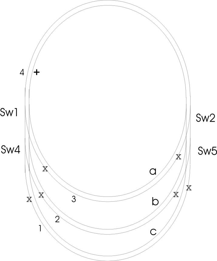
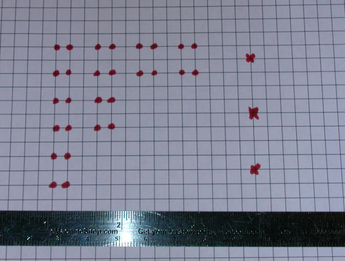
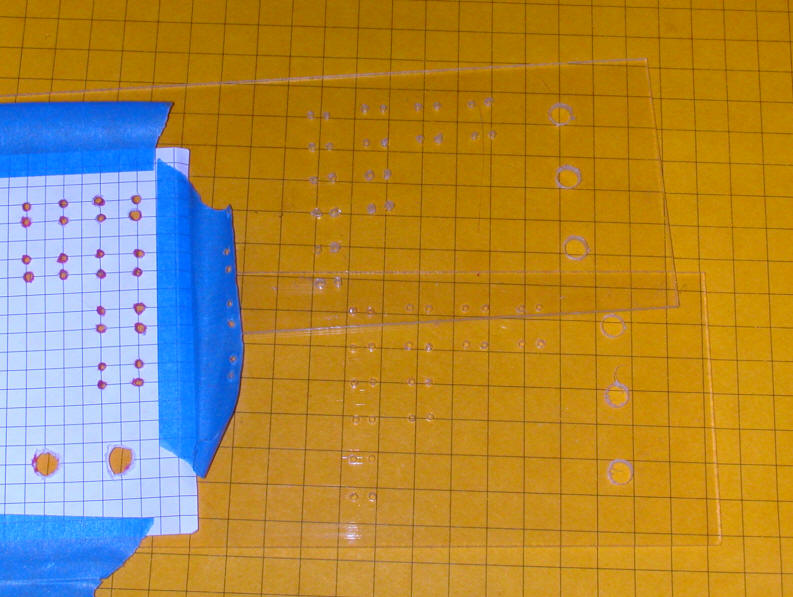
Here is the layout on the graph paper. The dots represent where 1/16" holes will be drilled for the diodes and the "x's" are where larger holes for the switches go.
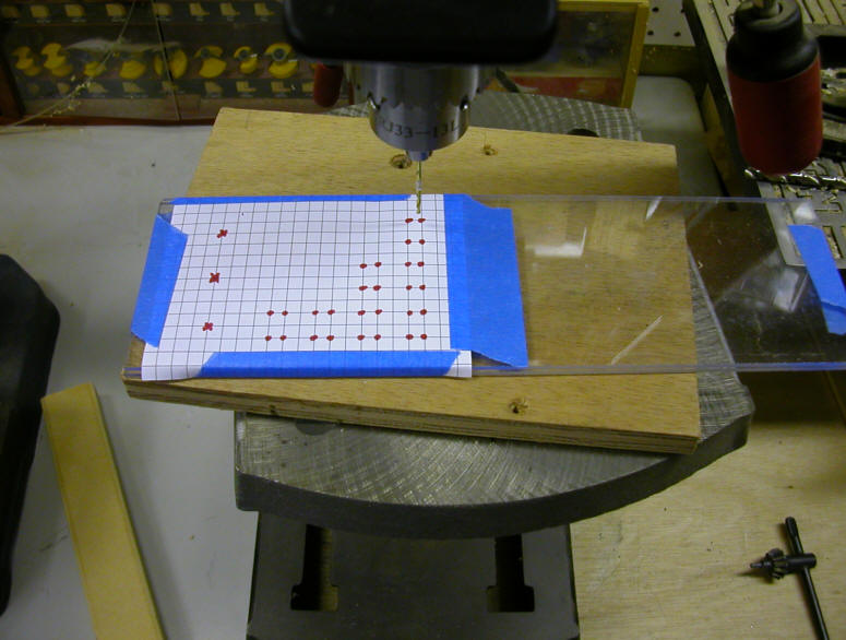
Once the layout is done tape the graph paper to your board material for drilling. In this photo there are two sheets of 1/8" Plexiglas taped together as I wanted to make two, identical units.
Here all of the holes have been drilled.
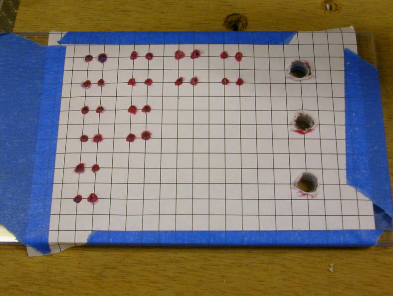
And here the drilled material is seen.
Placing Diodes
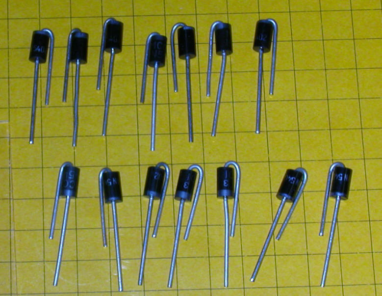
Bend 7 of the diodes so that the band is at the top of the bend and bend 7 so that the band is at the bottom.
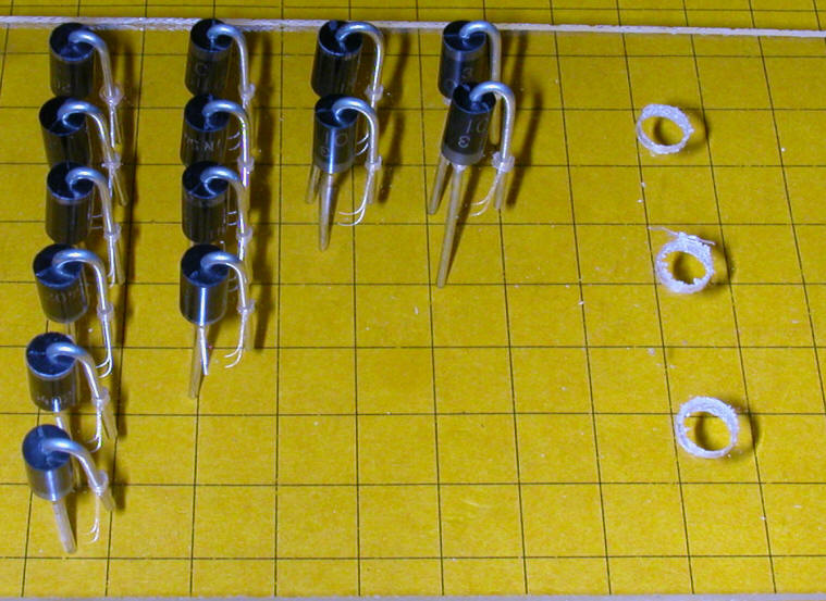
Insert the diodes in the holes with the ones with the band at the top in the upper row of each section and the others in the lower row. As you can see in this photo, the top four have their bands up, the next four have them down. The next two are up, the two below those are down and so on.
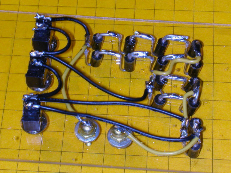
Here is the completed unit wired as in the schematic. In this top view you can see the two brass screws that were added as connection terminals. You can also begin to see how it is wired.
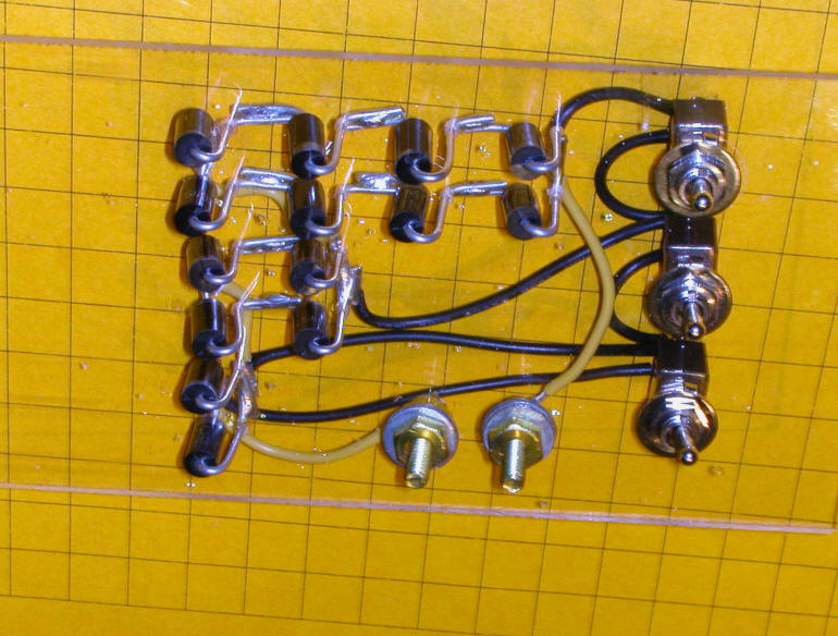
In this photo from the back the wiring is very clear. The leads from the diodes were bent over, clipped and soldered. Then wires were added to the terminals and to the switches. Don't be concerned about melting the Plexiglas with the soldering iron. Things get a little warm but I had no problems with melted plastic.
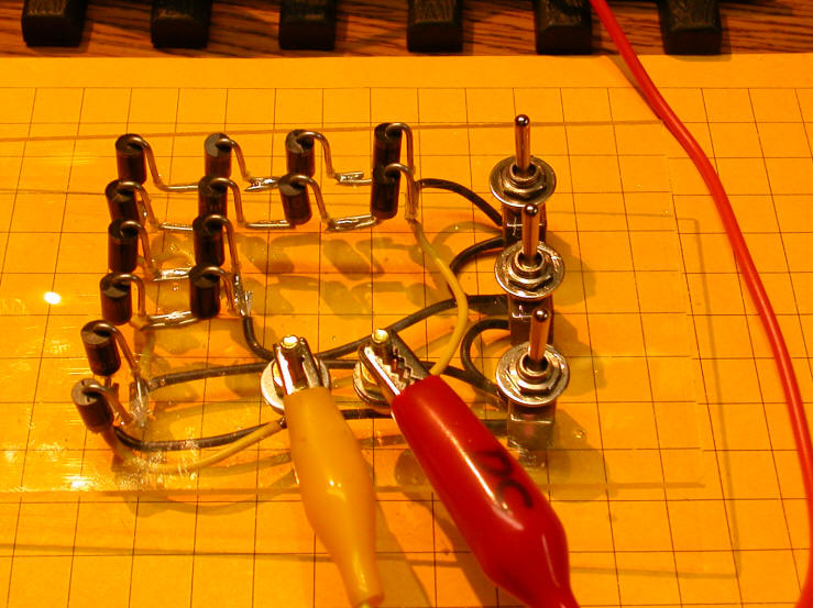
The completed unit is tested by connecting power to a test engine on rollers. One of the leads to the track has been removed and routed through the diode speed control as seen below. The switches are all "on" in this photo so there is no voltage drop. Throwing the top switch adds 4 diodes to the circuit, the center switch adds 2 diodes and the bottom one adds 1.
Use on Your Railroad
I hope you can see how this simple circuit can be used to control engine speed on your layout. You can even use this idea to speed engines up if you have one diode unit dropping the power to your whole layout and add blocks that get more voltage by bypassing some or all of the diodes. Lots of applications! Let me know what you come up with.
To Be Continued...
In the first installment we learned how to electronically control blocks. In the second we worked with switch motors. Diodes as speed control devices were explored here. Next time we'll take a close look at sensing where trains are located on your railroad. Stay tuned!
| Parts List |
| 14 - 3 amp silicon diodes - Radio Shack # 276-1144 ($1.59 for two)
or #276-1143 ($1.49 for two) - note that these are available at much
more reasonable prices from other sources, including the author!
Email dave@davebodnar.com for
details. 2 - brass screws or other connectors 1 - piece of Plexiglas or thin wood or circuit board 3 - SPST toggle switches - Radio Shack #275-624 ($2.99 each) Wire |