Part V - Microcontroller Integration & Software
revised 12-28-06
All of the things that have been described and utilized so far need to be pulled together by an intelligent device, a PICAXE microcontroller, and a program that tells it what to do.
When I start a project like this I like to come up with a list of things that I would like the finished device to do. The list of objectives below are the things that the microcontroller must do to manage the proper operation of all of the individual modules.
Objectives
The microcontroller that ties together the parts of this system must be able to do many things. Among them are:
Flowchart
A flowchart is another tool that helps in software design. This list of tasks is a text based flowchart that shows what the software does:
As you can see the logic is not too complex. In addition to what is listed above the software continuously does three other things:
The Circuit
The schematic below should look familiar since we have used parts of it in the other articles. In this diagram all of the pieces are connected to the PICKAXE 28X. This device is similar to the other PICAXE chips that we have used except that it has 28 pins. I chose to use it because of the number of devices that need to be observed and controlled. The cryptic notes that you see on the schematic (such as bw / ow and sensor3=green) are there to help me remember what color wire I used to connect various things (bw=blue/white wire, ow=orange/white, etc)
The one thing that is not included in the schematic is the LCD display. To simplify the project and speed its time to completion I opted to use an external LCD display controller. This is a chip from www.phanderson.com that accepts serial input at 2400 baud and displays the information that it receives on a 4 line X 20 character backlit LCD display. A complete description of the chip and its use is available at: http://phanderson.com/lcd106/lcd115.html . This unit and others from Peter Anderson are highly recommended.
Software
The software listing is below. It is fairly well commented and, for the most part, follows the logic that is described above. The items following SEROUT are text strings and commands that go to the LCD controller.
| 'd. bodnar 9-17-06 symbol relay1 = 0 symbol relay2 = 1 symbol relay3 = 2 symbol sensor1 = pin5 symbol sensor2 = pin6 symbol sensor3 = pin7 symbol EnterSw = pin2 'pin 13 on PICAXE - 1 when out, 0 when pushed symbol MenuSw = pin3 'pin 14 on PICAXE - 1 when out, 0 when pushed symbol EndSwitch = pin4 'pin 15 on PICAXE - 1 when out, 0 when pushed symbol swmotor1 = 3 symbol swmotor2 = 4 symbol swdir1 = 5 'h-bridge symbol swdir2 = 6 'h-bridge symbol nextloop = b4 symbol temp0 = b3 symbol temp1 = b5 symbol temp2 = b2 symbol temp3 = b6 symbol tempCL = b7 'temp storage of Current Loop Engine symbol Laps = w6 symbol EndFlag = bit8 symbol SwOneFlag = bit9 symbol SwTwoFlag = bit10 symbol SwThreeFlag = bit11 symbol versionW = 3 symbol versionD = 6 symbol dlay = 120 symbol SensorValue = b8 '= %01100000 ' %11100000 for 3 trains and %01100000 for 2 trains symbol PinsByte = b0 'using b0 allows us to access each sensor bit with bit5, bit6 & bit7 NextLoop = 0 'use 0-2 in stead of 1-3 for branch statement 'NOTE SensorValue must be set on first run with MENU!!!!!!!!!!!!!!!!!!! read 0, SensorValue if SensorValue <>%11100000 and SensorValue<>%01100000 then fixSensorValue goto NoNeedtoFix fixSensorValue: SensorValue=%11100000 'set to 3 trains if read is bad NoNeedtoFix: pause 5000 'pause while LCD wakes up and does test display if SensorValue=%11100000 then engines3a temp0=2:goto skipover1a: engines3a: temp0=3 SkipOver1a: serout 7, t2400,("?f?c0"):pause 200:serout 7,t2400,("?f?c0"):pause 200 '?c0 turns cursor off serout 7, t2400,("?Bff"):pause 200 serout 7,T2400,("Switch Controller?nd. bodnar 9-2006?nVersion ",#versionW,".",#versionD," Trains=",#temp0) pause 2000 'pause while LCD wakes up and does test display serout 7, T2400,("?x00?y3 MENU FOR SETTINGS")
|
User Interface
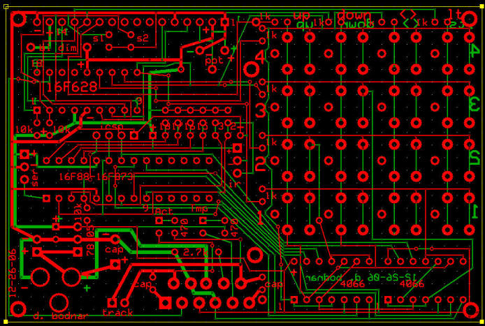
The user interacts with the unit through two buttons on the control panel, Menu and Enter, and a third that connects via the hand held Aristo-Craft remote control unit. The LCD display continuously shows each engine's progress as it navigates the layout. It also shows the switch status and number of laps that have been completed. The three "DIODE VOLTAGE CONTROL" switches control the speed of the trains once they enter a controlled block. The "NUDGE FORWARD" buttons allow you to manually active a block to move engines into position blocking sensors. The circuit board in the lower left corner is for the PICAXE and switch controlling H-Bridge chip.
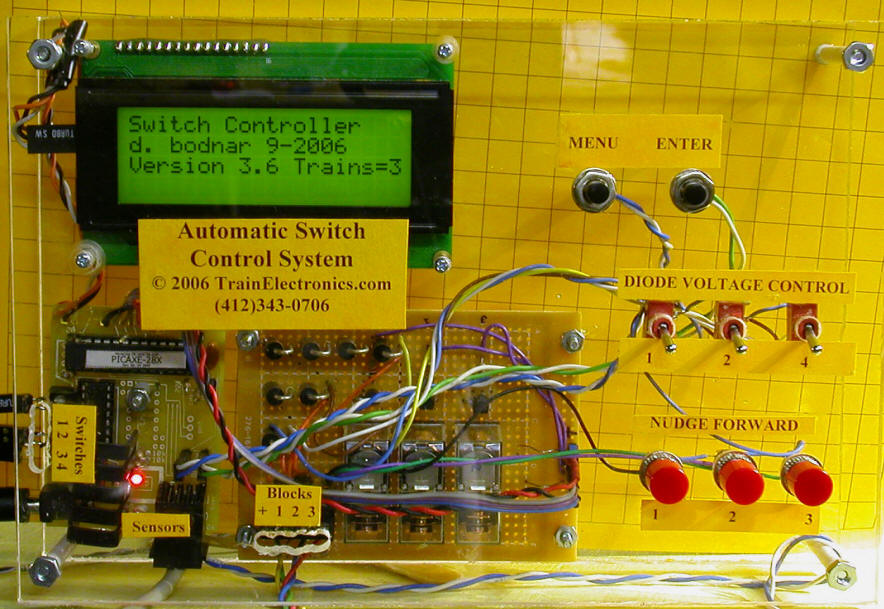
All of the external connections are in the lower left. Switches connect to the left. Under the word "Sensors" is the telephone cable that goes to the sensors. The block power cables are under "Blocks + 1 2 3".
Accessory Receiver
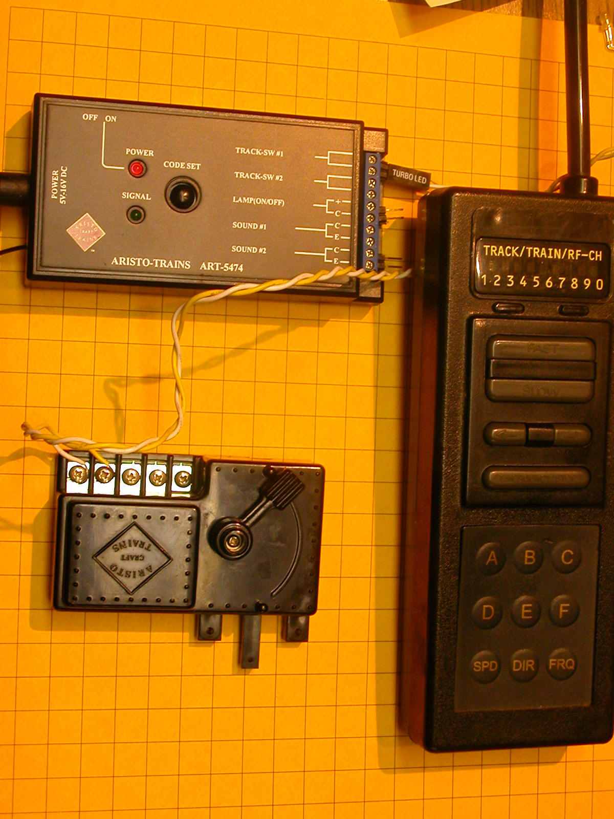
The connection on the schematic that is labeled "END switch / Sound 1 or Sound 2 on receiver" is the one that goes to the radio control accessory receiver, pictured below. This item is normally used to activate sound, lights or switches with the Train Engineer hand-held radio control unit. When properly configured pressing one of the accessory buttons on the transmitter activates the "END" switch on the controller. In this photo it is temporarily connected to a switch motor for testing.
Operation
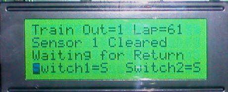
When first powered up the display shows copyright and version information. It then resets all of the switches and checks that all sensors are blocked by engines. If it finds that a sensor is not blocked it briefly applies power to the appropriate block moving the engine into position. This repeats till all sensors are blocked.
Once all of the engines are seen to be in position the user is asked to press ENTER to begin. At this point the engines leave and progress through the layout as previously described. One after the other one engine exits as the other two wait their turns.
Two Trains or Three?
You may notice that the display in one photo shows "Trains = 3". The layout that is controlled by this system is actually made up of two independent loops, one with two trains and two sidings and the other with three trains and sidings. Rather than make up two different systems, one for two and one for three trains, I chose to make two identical units. Either of them can be configured in software to control two trains or three. Even though a two train controller would have been much simpler to construct, in the long run it is easier to maintain only one design and one software revision.
Conclusion
As you can see this was something of an epic project to build and document. I hope that some or all of it was of interest to you and can be incorporated into your layout.
Why Not DCC?
A few LSOL readers asked me why I hadn't chosen to use DCC (Digital Command Control) to automate this layout. There are a number of reasons but the main one is that the layout's owner didn't want DCC. Other reasons for not using DCC for this project include:
Stay tuned...
I have really gotten used to adding "Stay Tuned..." to the end of each of these articles so I think I'll do it one more time so I can give a little peek at my next train automation project.
Maybe There is Room for a Bit of DCC After All...
In spite of what I said above about DCC it is an interesting technology and there are some advantages to using it. This is especially true if one can utilize a custom made DCC control system. Over the last few months I have built a few DCC controllers and am close to finishing up a PIC based control unit that duplicates much of what the controller described in this series can do.
There are still a lot of things to work out but you may see an article soon. Stay tuned...