Switch Mode DC-DC Step Down Converter
with Meter
d. bodnar revised 01-08-14
Introduction
A few years ago I wrote an article about a simple, inexpensive DC-DC
converter. See:
These converters work well but do not provide clean, liner DC power as the operate with PWM (also called PWC), a type pulsed DC that is used in many power units. Unfortunately some locomotives and their associated electronic sound systems do not work well with PWM.
I recently came across a more sophisticated DC-DC converter that operates as a switch mode power supply, the same type of power supply that is used in most computers. I did some experiments with it and found that its output voltage is very "clean" and works well with model trains.
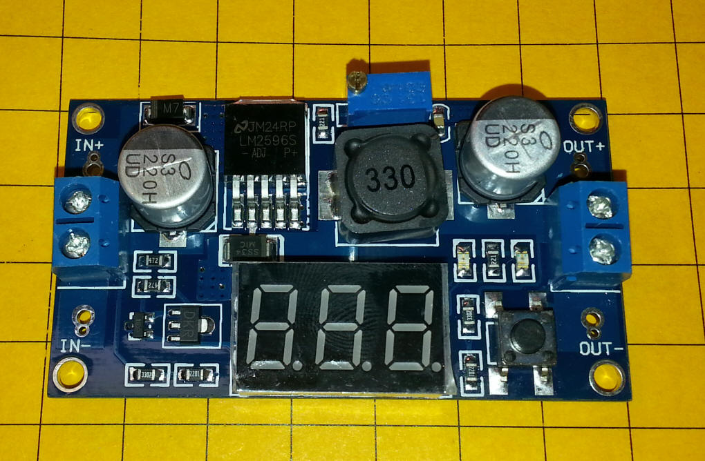
Unit Overview
The units are available on eBay and through many other on-line vendors.
Just search for
LM2596 4-40V to 1.25-37V DC Converter Step Down Adjustable Regulated+Volt Meter
They are also available from Marlin P. Jones for $10.95 : http://www.mpja.com/Adjustable-15-37V-DC_DC-Buck-Converter-with-LED-Volt-Meter/productinfo/30149%20PS
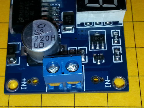
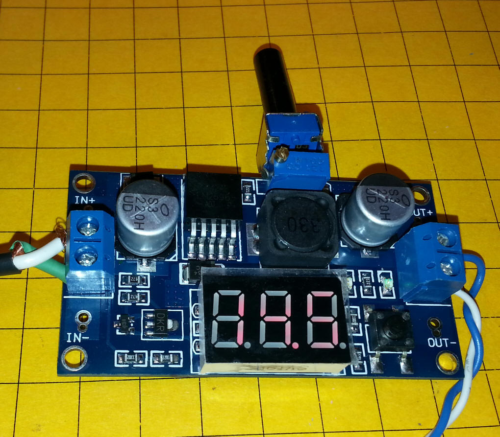
The unit has two connections on one end for input power. This can be from a retired laptop power supply or other source of DC voltage between 4 volts and 40 volts. My testing was done with a 18 volt Compaq laptop power supply.
Please note that you must observe proper polarity when connecting the input voltage!
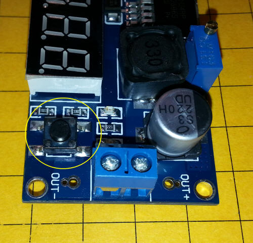
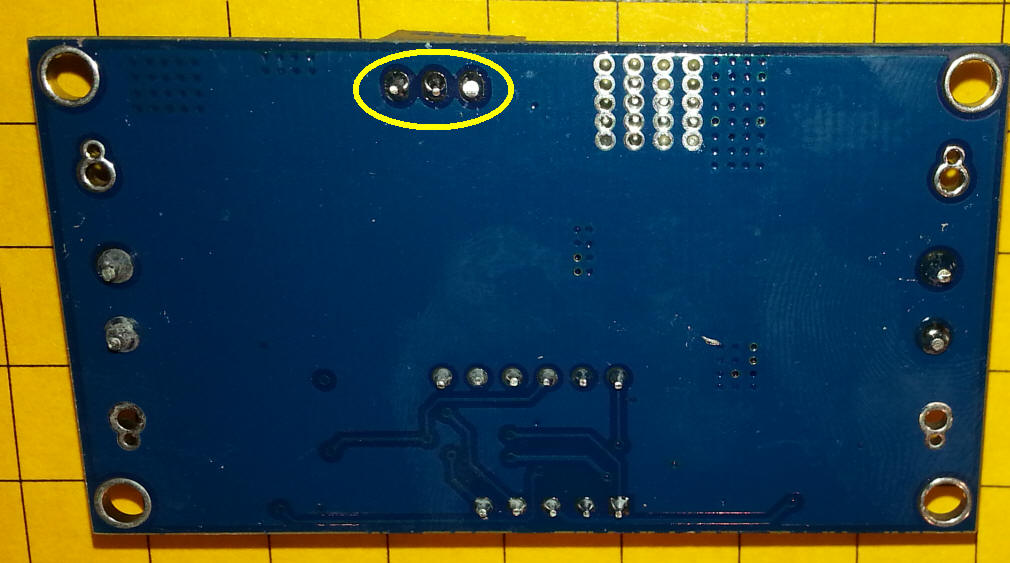
At the other end of the board are two output terminals. There is also a small button (circled in yellow) that toggles between showing the input or output voltage on the meter. To turn the meter display off just hold the button for a few seconds.
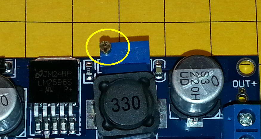
The output voltage can be varied by turning the small brass screw on top of the blue potentiometer.
This is rather inconvenient when running a train so I experimented with adding an external potentiometer for that would be easier to turn.
At first I thought I would have to remove the existing potentiometer. Here you can see where it connects on the back of the board.
On a hunch I tried setting the pot to its center position (about 1/2 voltage) and added a 10K potentiometer in parallel with the board's pot. I had to tweak the screw a bit to get a full range but it worked beautifully and is a much easier modification!!
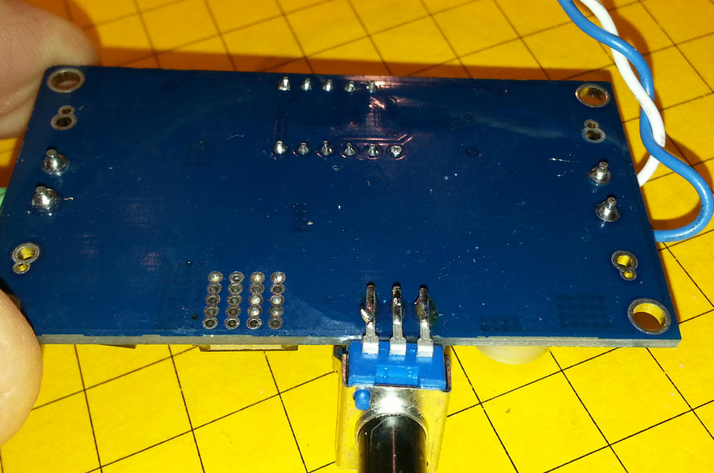
Here you can see the second pot mounted in parallel with the board's pot.
Testing
For testing I wired the output to a test track running an Eggliner.
The converter is rated at 2 amps continuous and 3 for a short time so it should
run many of our smaller G-scale trains without any problems. For HO and
smaller scales just about any locomotive should work.
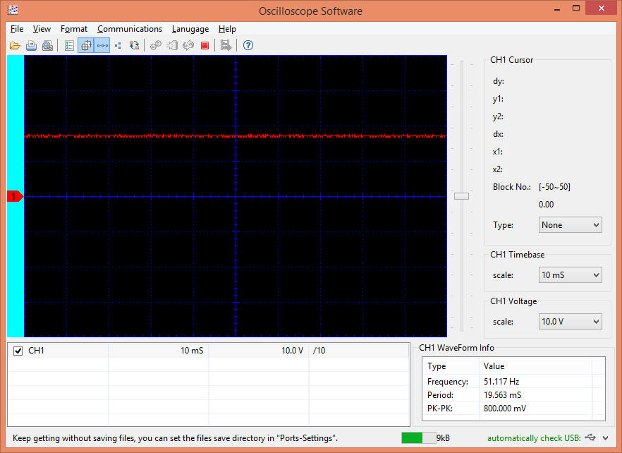
The output can be seen on the oscilloscope image below. There is very little ripple indicating a very clean DC power stream.
The next involved running three locomotives at the same time from the converter. The Eggliner was joined by two LGB 0-4-0's. The draw at 19 volts was 1.5 amps. At that load the IC on the board got to about 150 degrees F. The chip, an LM2596, that does all of the work and gets hot is rated at 125 degrees C (257 F) so we are well within that limit --- for more information on the chip see:
http://www.ti.com/general/docs/lit/getliterature.tsp?genericPartNumber=lm2596&fileType=pdf
Conclusion
For many of our power conversion needs this may be the best solution.
I have used these boards for many months in a variety of applications and have
been very impressed with their operation. Give one a try!
As always, if you have any questions, please drop me an email at dave@davebodnar.com