A Simple Constant Brightness LED Light

revised 4-4-06

I was recently asked to present a hands-on workshop for the Pittsburgh Garden Railway Society that had participants construct a constant brightness LED headlight.  You can give the same circuit a try by following these step-by-step directions.

LEDs are ideal for use in model train lighting as they can be wired so that they attain their full brightness at a low voltage, a must if working from track power.  In addition they also draw very little current, important for those of us who use battery power, and can be extremely bright.

There are some precautions that must be taken, however, as LEDs can easily be destroyed if they are fed an improper electron diet!

In order to protect the LED from excessive voltage and current a voltage regulator is used to keep the voltage to the LED constant.  Once the voltage is constant a current limiting resistor can be selected that will deliver an appropriate amount of current to the LED.

Detailed notes on selecting appropriate current limiting resistors are at the end of this article.


Parts
  1. LED - in this example we are using a very bright 3mm white LED.
  2. 78L05 or 7805 voltage regulator - the 7805 is larger than the 78L05 - it can deliver an amp of current where the 78L05 is only rated for 1/10 amp - either will do but the 7805 is larger and is overkill in this application
  3. Current limiting resistor - the LED used here works well with a 470 ohm resistor
  4. 1 amp diode - 1N4004 or similar
  5. Hookup wire
  6. 9 volt or similar battery for testing

Most of these parts are available from Radio Shack and other vendors.  To simplify things for those of you who would rather build than track down parts the author has complete parts kits available.  See the notes at the end of the article.

Tools
  1. Low power soldering iron - 25 to 30 watts with a very fine tip
  2. Rosin core (not acid core) solder, the thinner the better
  3. Small wire cutters
  4. Small pliers
  5. Block of foam insulation or Styrofoam
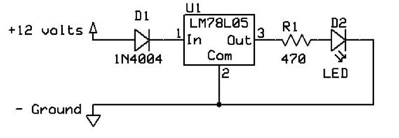
Schematic

The schematic is below.  The positive voltage (marked +12) can be anything from around 7 to 20 or more volts.  The circuit draws very little current and the regulator is rated for a maximum input voltage not to exceed 30 volts.  If you use more than 12 volts it is a good idea to touch the regulator and make sure it is not heating up as excess power must be dissipated as heat.  Note that the symbol for the diode, D1, has a vertical bar on the right side in this schematic.  Diodes must be installed with the proper orientation or they will not work properly.  There is a painted bar on one end of a diode, called the cathode, that corresponds to the bar on the right side of D1 in the diagram.  The other end of the diode is referred to as the anode.


Components

Here are the components needed.  From left to right they are 78L05, 1N4004 diode, LED and 470 ohm resistor.

The three leads on the regulator are, from left to right with the flat face showing as below, output, ground and input.

Component Preparation

Cut the leads on the resistor, LED and resistor as shown below.  Note that the lead that is to be cut on the LED is the longer one.  It is the positive lead.  If you are not sure which is which there is a notch or flat spot on the body of the LED next to the shorter, negative lead.

Carefully bend the leads on the voltage regulator as shown.  Make sure the flat, labeled face of the regulator is towards you.

Remove a bit of insulation from each end of the hookup wire.

Soldering Tips

This article is not meant to be a soldering tutorial but a few tips are in order:

  1. For soldering electronic circuits use a low wattage iron, 25-30 watts
  2. Use the best quality iron that is available.  Avoid inexpensive soldering irons as their tips are not of high quality and deteriorate in a matter of hours.  Weller makes an excellent soldering station for under $50.00, the WLC100.  It has adjustable temperature and can use a number of different sized tips.
  3. Tin and clean the iron's tip before each use.  Tinning means adding a small amount of solder to the tip so that it is shinny.  A dull tip does not transfer heat well and makes soldering very difficult.  Clean the tip by brushing it against a damp sponge.
  4. Tin the ends of components and hookup wire before soldering.  Taking the time to tin components is an excellent way to assure a good, fast connection
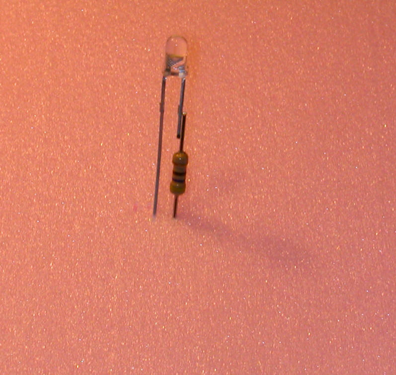
Soldering

Push the leads of the resistor and LED into a piece of foam to that they are held in proper orientation during soldering.  Note that the resistor and LED lead are not quite touching.  This was done so that the individual parts would show up in the photo.  Before soldering make sure that they touch evenly.

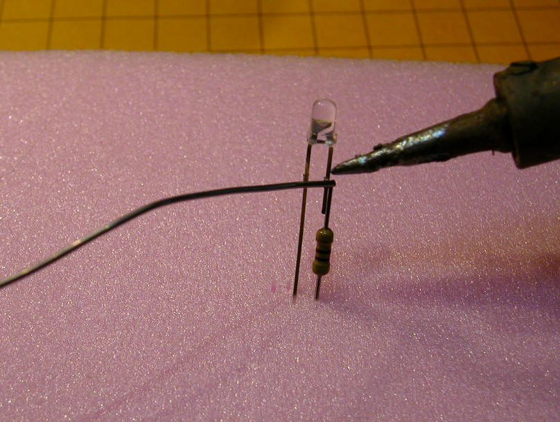
Clean the tip of your soldering iron on a damp sponge and tin it with solder until it is bright and shiny.  Put the tip of the iron on the joint between the LED and resistor until heat transfers and you can melt a bit of solder onto the joint.  Remove the iron and solder and allow to cool for a few seconds.  Try to do this quickly as heating the LED to an excessive temperature can destroy it.

Here is the soldered joint.

Push the unused LED's negative lead into the edge of the foam.  Push the input lead of the regulator into the foam so that the left hand, output lead of the regulator and the remaining resistor lead are lined up as shown.   Solder them together being careful not to touch the iron to the foam!

Align the negative lead of the LED and the center, negative lead of the regulator and solder as below.

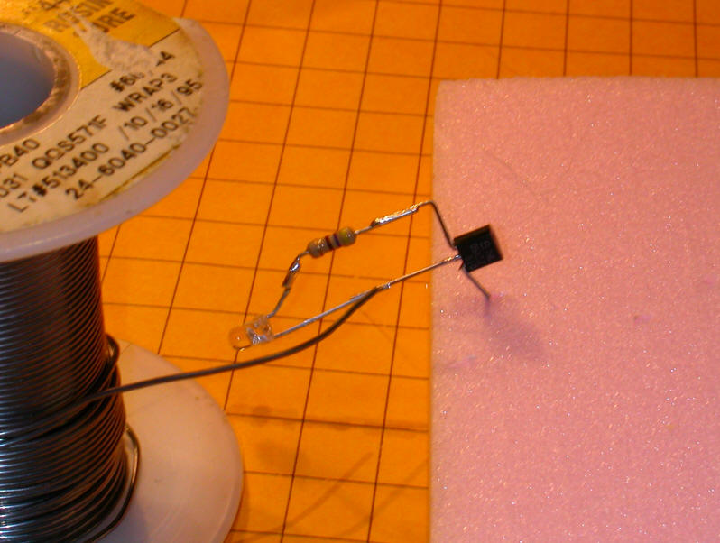
Bend the input lead of the regulator up a bit and push the positive lead (the one without the silver band) of the diode into the foam so that the banded lead of the diode and the input lead of the regulator line up.  Solder them together.

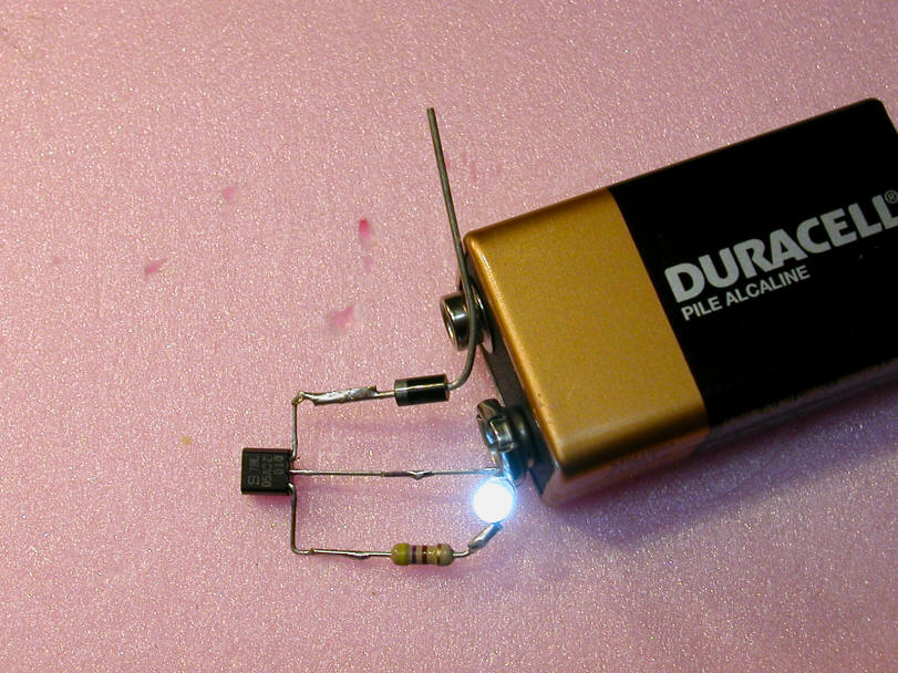
The circuit is just about complete and can be tested.  Carefully touch the center lead of the regulator to the negative terminal on the battery.  Touch the positive end of the diode to the positive terminal.  The LED should light!

Shorten  the red wire about 1/2 inch and tin the ends of the hookup wire with a bit of solder. 

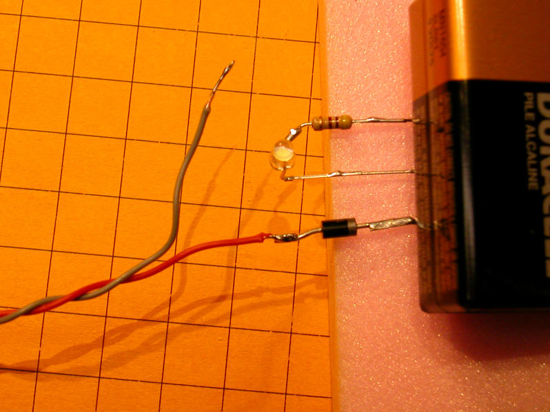
Tin the positive end of the diode then solder the positive (red) wire to it.  In the photos below the battery is being used as a weight to hold the components in place for soldering.

Solder the negative wire to the center lead on the regulator. 

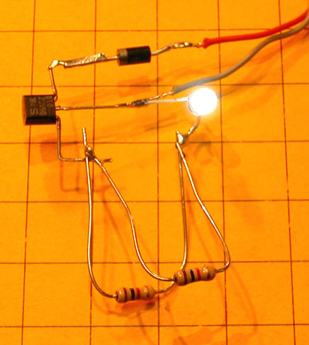
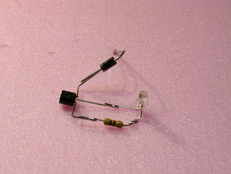
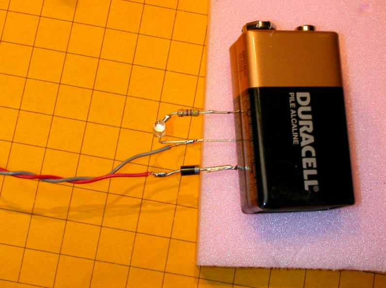
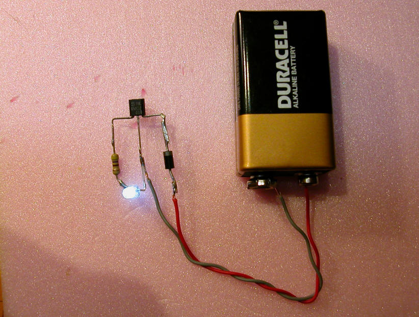
Here is the completed circuit.

Test by touching the red wire to the positive terminal on the battery and the black wire to the negative terminal.  Note that hooking them up backwards will not hurt the LED or regulator as the diode only permits current to flow in one direction.

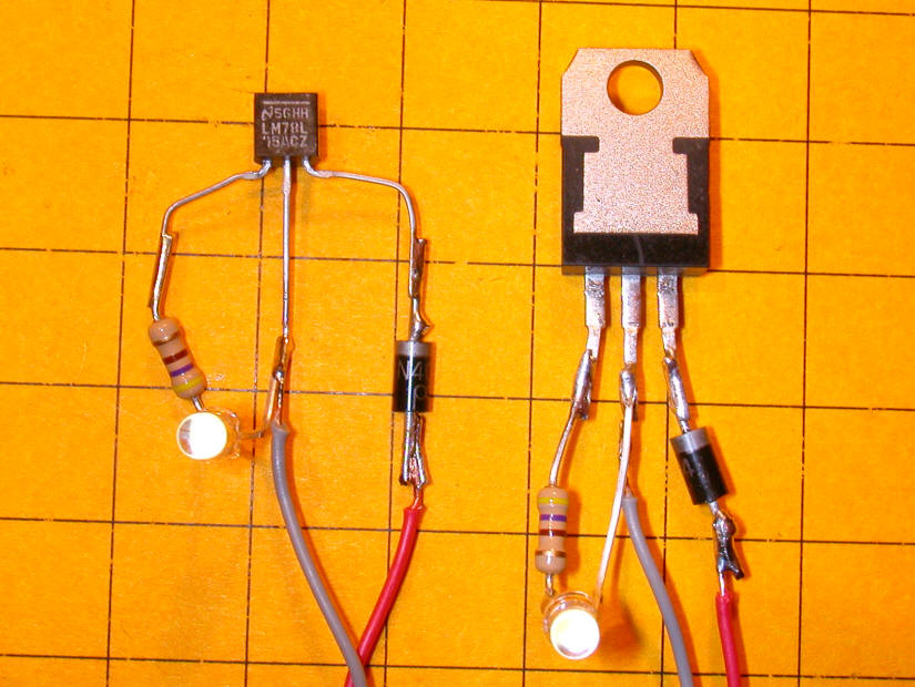
The wiring for the larger 7805 voltage regulator is identical with one exception, as you can see from the photo below.  The 78L05 is wired with its labeled, flat face towards you but the 7805 is wired with the labeled face away from you.

Notes:
  1. The circuit used here is ideal for a headlamp on an engine as it will only light when the voltage is applied with one polarity.  Test the polarity when installing the light so that the LED lights when the engine is going forward.
  2. Another similar circuit, perhaps with a red LED, could be wired to come on at the rear of the train when the train runs backwards.
  3. Power can be found inside of most engines either by following the wheel pickups or by looking for a circuit board where the contact wires terminate.  Test the connections with an ohm meter between one of the pickup wheels and each of the contacts to locate the left and right wheel pickups.
  4. The 78L05 regulator and 1N4004 diode used here can accommodate a number of LEDs before becoming overloaded.  Most LEDs draw less than 20 ma and the regulator is rated for 100 ma.  If you want to light a car or other area with more than 5 or 6 LEDs use a 7805 regulator which is rated for 1000 ma or 1 amp.
  5. Some engines already have a 5 volt regulator, usually a larger 7805.  If you can find that device you can skip the regulator and diode used here and just use the current limiting resistor and LED.
  6. If there is little space for installation of the LED in a headlamp, such as in the photos of an external LGB headlight fixture below, you can put all of the parts but the LED inside of the engine and run wires for just the LED to the headlamp location.
 

Compact Construction

Leads on the voltage regulator, resistor and diode can be shortened to give a more compact package.  The following configuration is suggested. 

The negative, shorter, LED lead goes to the center lead of the regulator and the positive lead of the LED goes to the resistor.  Power leads are soldered to the center and right hand leads of the regulator.

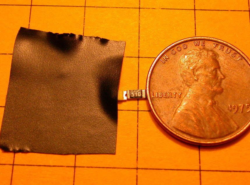
Surface Mount LEDs

If space is at a premium and you have a good magnifying glass, surface mount LEDs and resistors can be used.  The device on the right, marked 510, is a resistor and the other device is the LED.

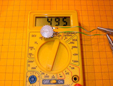
The negative terminal of this surface mount LED is marked with a line on the back of the case.  Other surface mount LEDs may be marked in a different manner.  If in doubt apply voltage, through a 1000 ohm resistor, to each side of the LED.  Reverse the leads if it does not work.

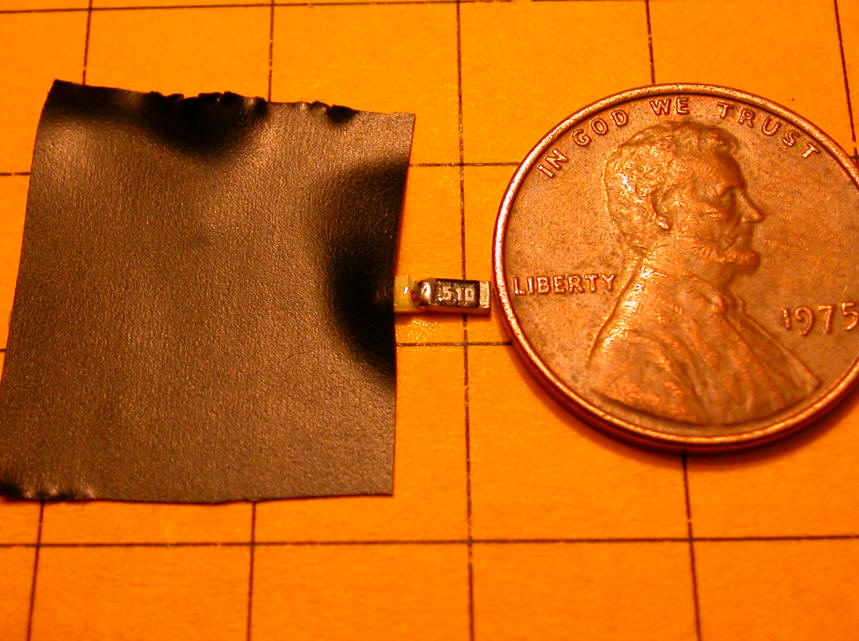
Use a piece of electrical tape to hold the LED in place.  Push the resistor against the positive terminal and hold it in place with a penny.

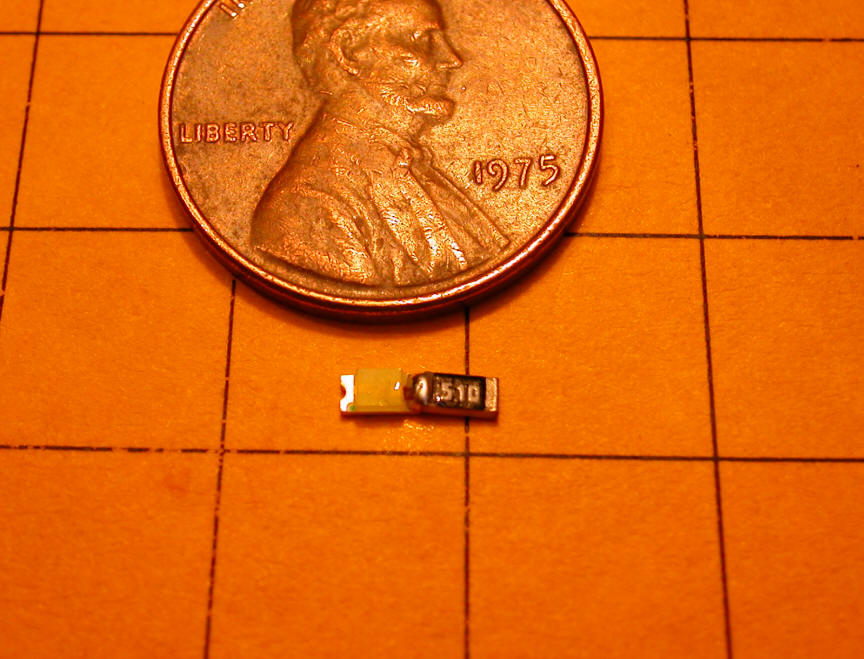
Using fine solder and a fine tip iron place a bit of solder in the joint between the LED and the resistor. 

Note that the resistor being used below is marked "510" - this is a 51 ohm resistor.  (Take the first two digits, 51 in this case, and multiply them times 10 to the power of the third digit, 10 to the zero power in this case, which is 1 - a resistor marked 513 would be 51,000 ohms as 10 to the third power is 1000.  51 x 1000 = 51,000)

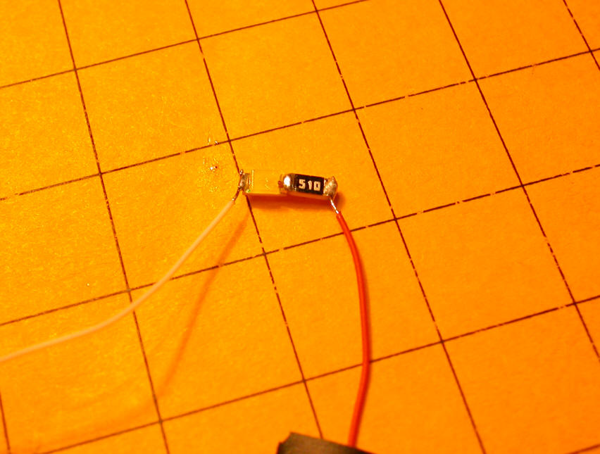
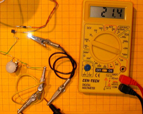
Add wires to the negative side of the LED and the resistor, connect to 5 volts and you are done!

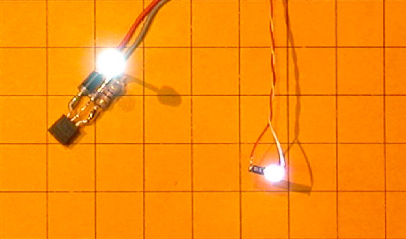
Here you see a 3mm white LED on the left and the surface mount unit on the right.  The brightness is similar but the 3mm unit is much more focused.  The surface mount is more of a flood lamp.


Selecting Current Limiting Resistors

LEDs must be used with a current limiting resistor.  If a resistor is not used the LED has the potential to draw enough current from the circuit to destroy itself. 

Some folks prefer a mathematical computation to determine the value of the current limiting resistor.  If that is your preference see item 5 in the list below.  If you are one who prefers a more "hands-on" approach one of the first four items in the list below may be for you.

1.  Brightness only:

Inexact method - no tools or special components- can destroy the LED

  1. Insert a 1000 ohm resistor in series with the LED and the 5 volt supply
  2. Observe the brightness of the LED
  3. Temporarily place a 2nd 1000 ohm resistor in parallel with the first resistor - this gives a resistance of 500 ohms
  4. Observe the brightness.  If it increases repeat with a 3rd 1000 ohm in parallel giving 333 ohms.  If it does not get brighter use this resistance value
  5. Repeat as needed making sure you don't get more than five or six 1000 ohm resistors in parallel, dropping the resistance below 100 ohms

Here you see two 1000 ohm resistors in parallel.

2.  Temperature:

Inexact method - no tools or special components- can destroy LED

  1. Use the above procedure checking the temperature of the LED at each step
  2. The best way to check the temperature is to touch the LED with a finger.  Once you are sure it is not too hot touch it to your lips or to your cheek.
  3. Once the LED starts to get the least bit warm use that resistance or one a bit higher in value. 
  4. The objective is to keep the LED from getting anything but a bit warm.  Never let it get hot.
  5. Remember, the higher the resistance, the lower the current and the dimmer and cooler the LED will be
3. Variable resistor:

Inexact method - requires a basic volt-ohm meter - can destroy LED

The meter used here is a very inexpensive unit that is available from HarborFreight.com for under $10.00.  I have seen them on sale for less than $5.00 at the local Harbor Freight store.

http://www.harborfreight.com/cpi/ctaf/displayitem.taf?Itemnumber=92020


  1. Use either of the above procedures with a variable resistor or potentiometer in place of the 1000 ohm resistors
  2. Insert a 1000 ohm variable resistor in series with the LED and 5 volt power supply
  3. Make sure you start with the potentiometer set to its HIGHEST value
  4. Adjust the pot, turning it so the resistance decreases, until the brightness of the LED ceases to increase or until it begins to get a bit warm
  5. Remove the pot from the circuit and measure its resistance.  Use that value in a fixed resistor

Note the wiring of the pot in the schematic and photo below.  It has 3 leads, one on either side and one in the center.  The center lead and the one on the right are wired together.

Here the resistance of the potentiometer measures 495 ohms.

4. Current used:

Exact method - requires a basic meter- unlikely to destroy LED - you need to have the LED's specifications

  1. Find the LED's specification sheet. 
  2. On the spec sheet find the recommended current for the LED
  3. Set the meter to the milliamp (ma) setting
  4. Put the probes from the meter in series with the 5 volt power supply and the resistor
  5. Using either a 1000 ohm potentiometer or a number of 1000 ohm fixed resistors as above light the LED and take note of the current reading on the meter
  6. Change the resistance.  When the current  shown on the meter reaches the recommend value you have identified the proper resistor to use

Note that the meter is set to the 200 ma range and that the display shows a bit over 20 ma.  The LED being tested is rated for a maximum of 30 ma forward current but is quite bright at 21.4 ma.

 5.

For those of you who are more mathematically inclined!

One can, of  course, determine the proper resistor mathematically.  Light Emitting Diodes don't adhere strictly to Ohm's Law but it is a simple matter to work around this.

  1. Gather the recommended current and forward voltage (sometimes called forward voltage drop) from the LED's data sheet.  The specifications for the LEDs I am working with here show 3.4 volts forward voltage and 30 ma maximum current.  To be safe keep it under the maximum and use 25 ma

  2. Before applying Ohm's Law subtract the forward voltage from the supply voltage.  In our case we are supplying 5 volts so the difference is 5 volts - 3.4 volts = 1.6 volts

  3. Divide this voltage by the current (in amps).  This would be 1.6 / .025 (25 ma = 0.025 amps) = 64 ohms

  4. Another example:   I have bright red LEDs that have a forward voltage of 2.1 volts and a recommended current of 20 ma.  The resistor, assuming a 5 volt supply, would be (5-2.1) / 0.020 = 2.9/0.020 = 145 ohms

  5. The formula is         Resistance = (Supply Voltage - Forward Voltage) / Current (in amps)


Parts Kits:

A complete parts kit is available from the author.  Contact dave@davebodnar.com to order.

The kit contains:

  • 2 @ 3mm white LEDs (very bright!)

  • 2 @ 470 ohm current limiting resistors

  • 2 @ 7805 or 78L05 voltage regulator (your choice)

  • 2 @ 1N4004 (or similar) diode

  • short length of hookup wire

The cost is $3.00 per kit + $1.00 shipping for up to 5 kits.

Other LEDs are available including 5mm white, 3mm green, 3mm red