|
This video shows the lighthouse circuit over an hour or so as the sun sets - the video has been shortened to about 1 minute.
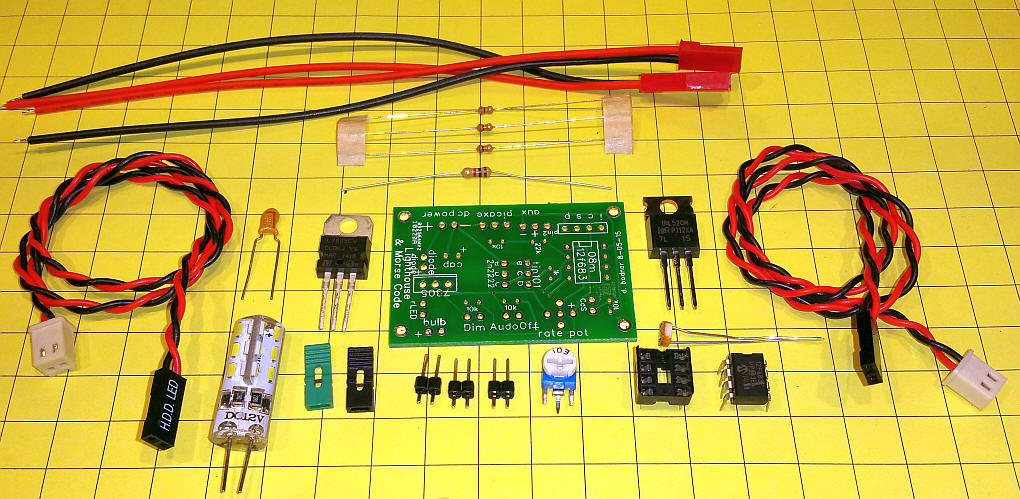
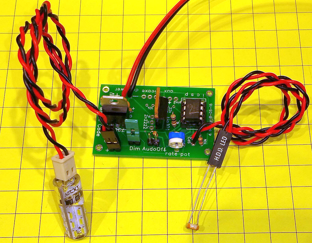
The lighthouse circuit and software have been updated to utilize very bright, very low power LED lamp modules. These devices contain 24 individual LEDs arranged in an array that sends light out in every direction. They are very bright while only drawing a small fraction of the power that halogen bulbs consume. In order to make these modules work in a realistic way the software has been rewritten and a faster microcontroller has been used. Features include:
The difference in color between the bright white LED module and the warm white module is shown in this video. The warm white is on the left and the bright white is on the right.
|
|
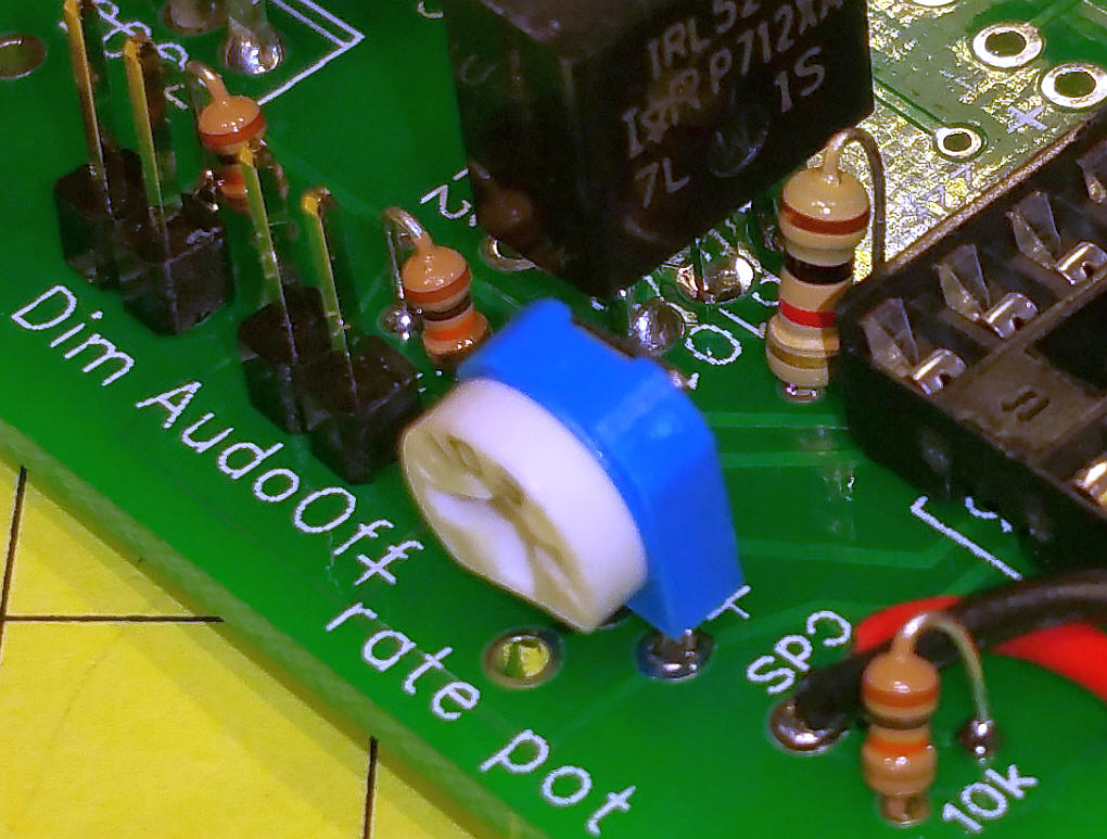
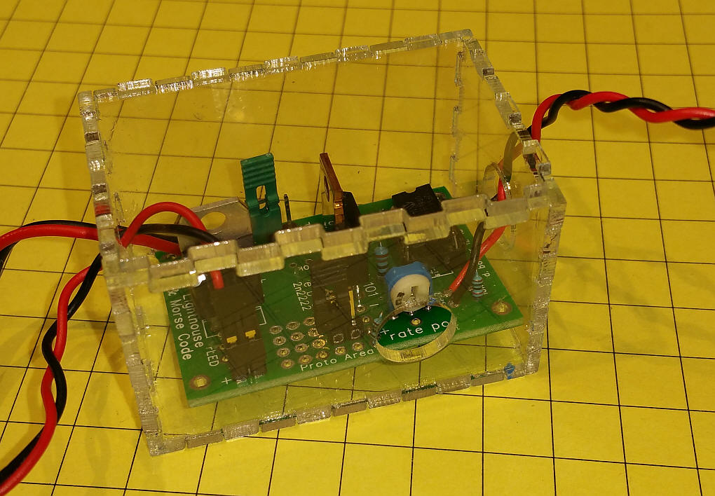
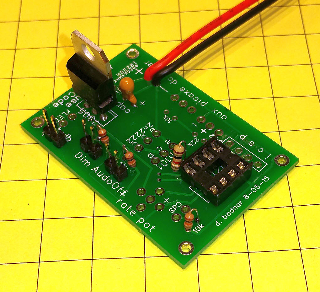
The behavior of the lighthouse beacon can be
changed in a number of ways. In its simplest configuration the
light flashes at a rate determined by the rate pot as soon as power
is applied and continues to flash until power is removed. The
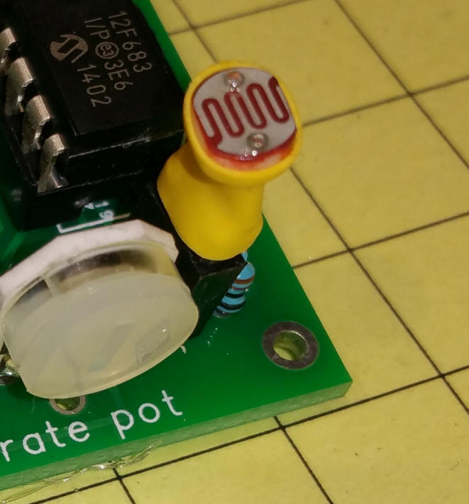
CDs light sensor can be used to turn the lighthouse beacon's LED
module on only after dark. When the sun comes up the module
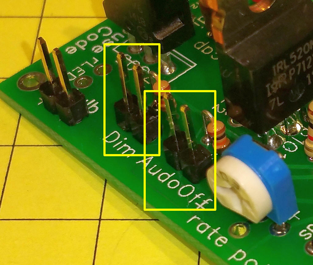
remains off. A jumper can be installed to have the unit
automatically turn off approximately six hours after sunset.
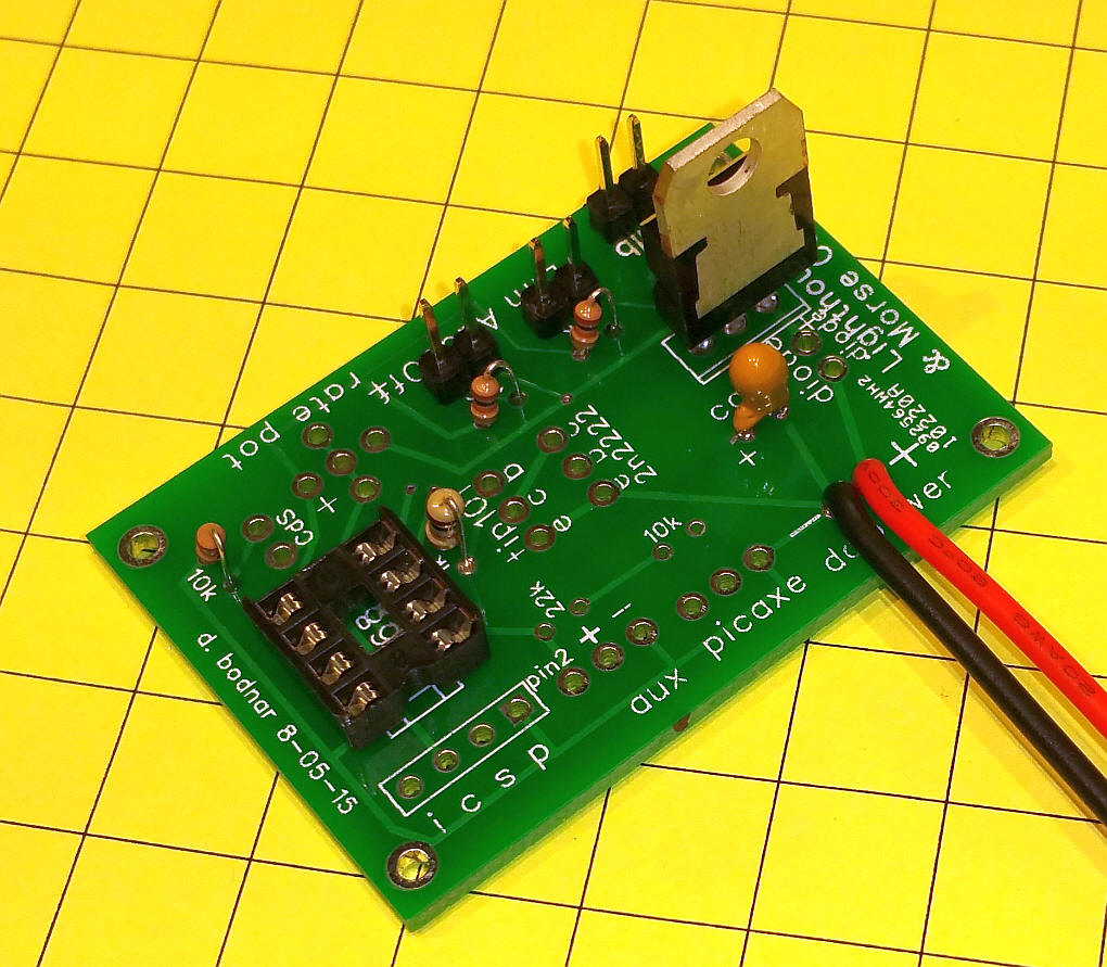
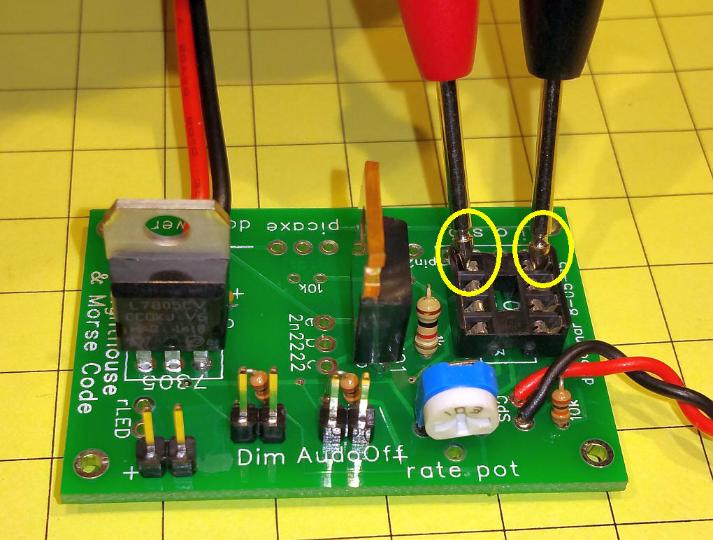
The lighthouse comes back on for six hours after the sun goes down. Rate Pot:
Turn clockwise to increase the time between
flashes (maximum about 1 minute) Auto Off Jumper: if on the lighthouse shuts off after 6 hours of darkness - remove to disable auto-shutoff Leave the jumper pins open (as shown above) to disable the 6 hour time off after sundown. Place a jumper on the pins to enable the 6 hour time off (note: CDs must be installed - see next section) Note: the time that the unit remains on can vary from 6 to nearly 8 hours depending on how often the lighthouse beam flashes. More flashes = longer on time., less frequent flashes = shorter on time. Dim Jumper: if removed the lighthouse lights dimly between flashes - if placed on the pins the bulb goes dark between flashes. The dim jumper keeps the bulb lighted dimly between flashes if not jumpered and completely off in between flashes if the two pins are jumpered.
CDs Sensor: Install the CDs light sensor to activate "on when dark, off when light." When shipped the CDs sensor will be installed at the end of a wire extension allowing it to be mounted outside of the lighthouse.
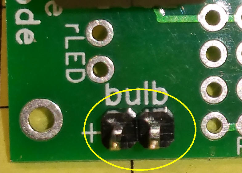
Bulb Installation:
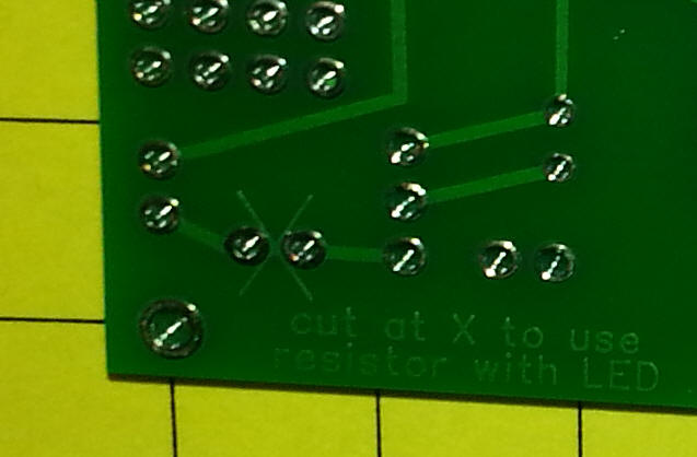
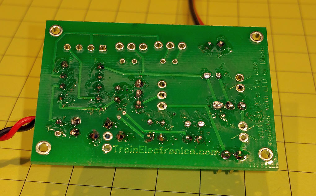
These lights can be installed either way but standard LEDs must have the anode connected to the "+" terminal and the cathode to the other terminal. With standard LEDs you will need a current limiting resistor. That can be installed in the two holes labeled "rLED". You will also have to cut the trace between these two holes on the back of the board.
|